
An optical module serves as the backbone of modern fiber-optic communication. Its appearance often resembles a compact rectangular device, designed to fit seamlessly into networking equipment. You’ll find its structure carefully engineered to house advanced components that convert electrical signals into optical ones and vice versa.
Optical transceiver modules are pivotal in modern networking, facilitating the conversion between electrical and optical signals. Despite the variety in types and designs, these modules share a common structural framework.
In this blog, we’ll explore the core structure of an optical transceiver, explaining the function of each part and how they work together to ensure seamless fiber optic communication.
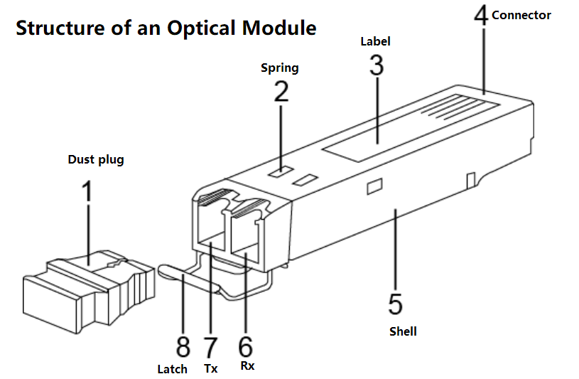
External Structure of an Optical Module
Component | Description |
|---|---|
1. Dust Plug | Protects optical fiber connectors, adapters, and ports from external contaminants and damage. |
2. Spring | Ensures a secure connection between the optical module and the device's optical port. |
3. Label | Displays key parameters and vendor information of the optical module. |
4. Connector | Connects the optical module to a board for signal transmission and power supply. |
5. Shell | Protects internal components; types include 1×9 and SFP shells. |
6. Receive Optical Bore (Rx) | Receives optical signals. |
7. Transmit Optical Bore (Tx) | Transmits optical signals. |
8. Latch | Facilitates the insertion and removal of the optical module; color-coded for easy identification. |
1. Dust Plug
Function:
Protects the fiber optic connectors, adapters, and optical bores from dust, moisture, and physical damage.
Essential for maintaining signal integrity and preventing contamination.
Why It Matters:
A contaminated optical port can lead to signal loss or failure, making dust plugs critical for storage and handling.
2. Spring (SFP Modules Only)
Function:
Ensures a secure connection between the optical module and the device’s optical port.
Provides mechanical stability to prevent disconnection.
Note:
This component is only present in SFP modules, as larger form factors (QSFP, OSFP) use different latching mechanisms.
3. Label
Function:
Displays key parameters (wavelength, transmission distance, data rate).
Includes vendor information (e.g., LINK-PP branding, compliance certifications).
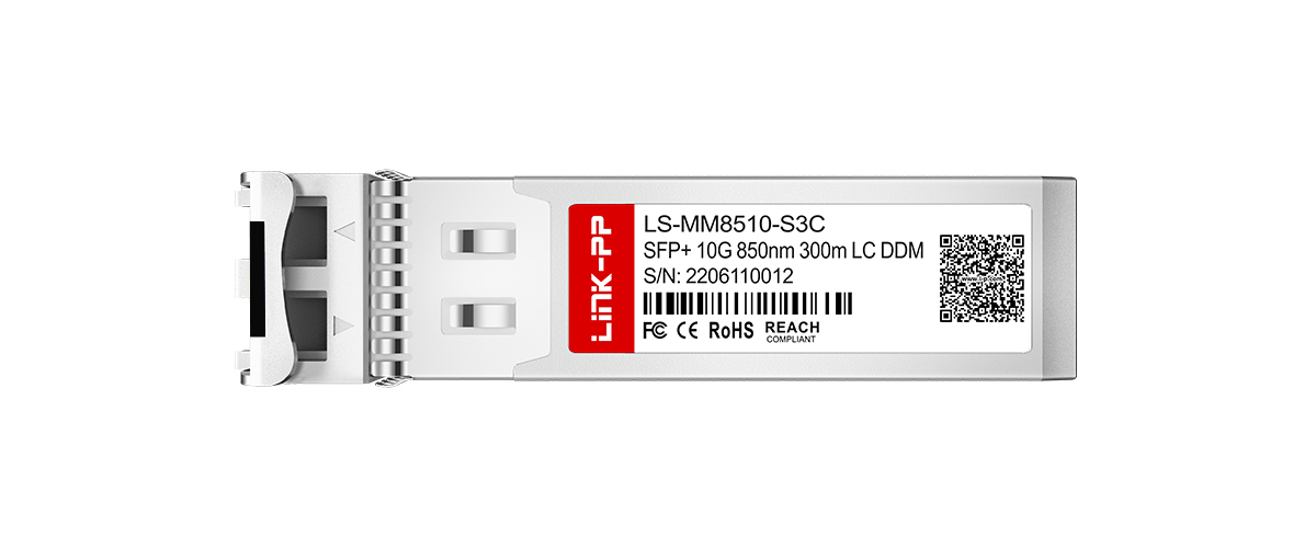
Example from LINK-PP:
A LINK-PP 10GBASE-SR SFP+ LS-MM8510-S3C label shows:
✔ Part Number: LS-MM8510-S3C
✔ Form Factor: SFP+
✔ Data Rate: 10G
✔ Wavelength: 850nm
✔ Max Distance: 300m
✔ Wavelength: 850nm
✔ Connector: LC
✔ DDM Support: Yes
4. Connector (Electrical Interface)
Function:
Connects the optical module to the host device (switch, router, server).
Transmits electrical signals and supplies power to the module.
5. Shell (Housing)
Function:
Protects internal components from EMI (electromagnetic interference) and physical damage.
LINK-PP’s Robust Design:
Our transceivers feature reinforced metal shells for superior heat dissipation and durability.
6. Receive Optical Bore (Rx)
Function:
Receives incoming optical signals from the fiber.
Contains a photodetector (PIN or APD) to convert light into electrical signals.
Key Specs:
Sensitivity: Minimum detectable light power (e.g., -23dBm for 10G LR).
Wavelength: Must match the transmitter (e.g., 1310nm for 10GBASE-LR).
7. Transmit Optical Bore (Tx)
Function:
Emits outgoing optical signals into the fiber.
Contains a laser diode (VCSEL, DFB, or EML) for signal generation.
LINK-PP’s Laser Technology:
We use high-quality DFB lasers for long-haul single-mode applications, ensuring low jitter and high reliability.
8. Latch (Module Extraction Mechanism)
Function:
Allows easy insertion and removal of the optical module.
Color-coded for quick identification (e.g., blue for 10G, green for 25G).
Pro Tip:
Always disengage the latch gently to avoid damaging the port.
Why Choose LINK-PP Optical Transceiver Modules?
LINK-PP is a renowned manufacturer specializing in high-quality optical transceiver modules. Their products are known for:
Reliability: Ensuring consistent performance across various networking environments.
Compatibility: Designed to work seamlessly with a wide range of networking equipment.
Compliance: Adhering to industry standards and certifications for quality assurance.
Quality Assurance:Every module undergoes strict testing for optical power, temperature stability, and compatibility.
Tip: Always consider the module's compatibility, performance, and certifications to ensure it meets your system's requirements.
FAQ
What is the purpose of an optical module in optical networking?
An optical module converts electrical signals into optical signals and vice versa. It enables high-speed data transmission in optical networking systems, ensuring efficient communication between devices.
How do the transmitter and receiver work in an optical module?
The transmitter converts electrical signals into light for transmission through fiber optics. The receiver captures the light signals and converts them back into electrical signals for processing.
Why is heat dissipation important in optical modules?
Heat dissipation prevents overheating, which can damage components and reduce performance. Effective cooling mechanisms, like heat sinks and thermal pads, ensure reliable operation, especially in high-speed applications like data center switching.
What factors should you consider when choosing an optical module?
You should evaluate compatibility, data rate, transmission distance, and certifications. These factors ensure the module meets your network's requirements and performs reliably in optical networking systems.


