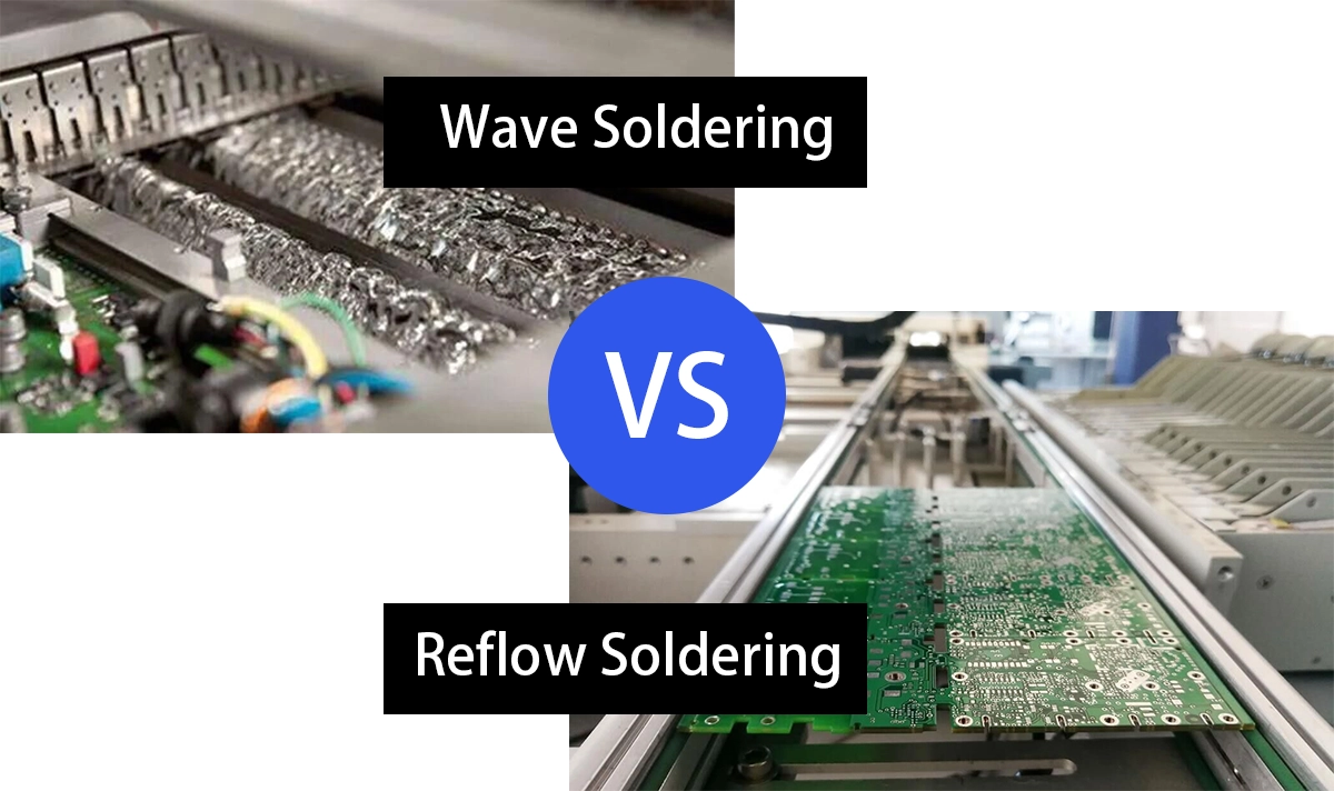
Comparing Wave and Reflow Soldering Methods
Explore key differences between wave and reflow soldering processes.
Features | Wave Soldering | Reflow Soldering |
|---|---|---|
Component Compatibility | Best for through-hole components. | Ideal for surface-mount devices. |
Process Method | PCB passes over molten solder wave. | Solder paste melts in controlled oven. |
Production Volume | Suited for high-volume bulk production. | Better for smaller or complex batches. |
Equipment Complexity | Simpler machines, fewer moving parts. | Requires ovens, stencils, pick-and-place. |
Board Complexity | Works well with simple, single-sided boards. | Supports complex, double-sided, fine-pitch boards. |
Cost Efficiency | Lower cost per unit in large runs. | Higher upfront cost, saves on defects. |
Throughput Speed | Processes multiple boards simultaneously. | Matches placement speed, slower for large runs. |
Quality Control | Requires precise timing to avoid defects. | Offers real-time monitoring and precise control. |
Environmental Needs | Needs controlled environment to reduce defects. | More flexible, less strict environmental control. |
When you compare wave soldering vs. reflow soldering, you see clear differences in the soldering process. Wave soldering uses a molten solder wave to connect components, while reflow soldering heats solder paste to bond parts. Your choice affects production speed, cost, and PCB assembly. Wave soldering fits through-hole components, but reflow soldering works best for surface-mount devices. Both soldering methods support different PCB assembly needs. You must select the right soldering process for efficient production and reliable PCBA. Wave soldering vs. reflow soldering highlights how each method shapes your results.
Key Takeaways
Wave soldering works best for high-volume production of through-hole components, offering fast, cost-effective assembly with strong, reliable joints.
Reflow soldering suits complex, high-density boards with surface-mount devices, providing precise control, flexibility, and high-quality results.
Choosing the right soldering method depends on your board design, component types, production volume, and quality needs to ensure efficient and reliable PCB assembly.
What is Wave Soldering?
Overview
Wave soldering is a soldering process used primarily for through-hole components in printed circuit board (PCB) assembly. It involves passing the bottom side of a PCB over a wave of molten solder created in a heated solder pot.
Process Steps
You follow a series of precise steps in the wave soldering process:
Flux Application: You apply flux to the bottom of the PCB. This step prevents oxidation and contamination. You can use a fine mist spray or a foam head to add the flux.
Preheating: You preheat the board to stabilize temperature and reduce thermal shock. Careful control of preheat time and temperature ensures the flux activates without damaging the board.
Solder Wave Contact: You move the PCB over the solder wave. The contact lasts 2 to 4 seconds. You adjust conveyor speed and wave height to control this step.
Cooling: You cool the board using air or water. This prevents distortion or damage.
Inspection: You check the solder joints visually or with automated inspection to confirm quality.
Tip: Proper timing and temperature control at each step help you avoid defects and ensure reliable soldering.
Applications
Wave soldering is widely used for through-hole PCB assembly in high-volume electronics manufacturing. It reduces defects and repair costs while ensuring strong, reliable joints—ideal for industrial and consumer applications. Optimizing the process with production data improves both quality and efficiency.
What is Reflow Soldering?
Overview
Reflow soldering is the most widely used soldering technique for surface-mount technology (SMT) and through-hole reflow (THR) components in modern PCB assembly. It uses solder paste and a controlled heating process to form precise and reliable solder joints.
Process Steps
You follow several steps in the reflow soldering process:
Solder Paste Application: You use a stencil to deposit solder paste on the PCB pads. Advanced stencil technology, like laser-cut stainless steel, helps you achieve precise results.
Component Placement: You place surface-mount devices onto the solder paste. Automated machines ensure accuracy.
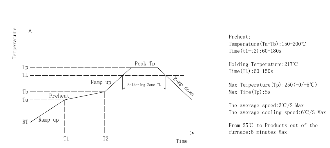
Preheating: You gradually heat the board to activate the flux and prevent thermal shock.
Reflow: You pass the board through a multi-zone oven. Forced convection and nitrogen atmosphere help you maintain uniform heating. The solder melts and forms strong joints.
Cooling: You cool the board to solidify the solder.
Inspection: You use automated inspection to check for defects and improve quality.
Tip: Careful control of temperature and paste quality reduces defects and increases reliability.
Applications
You find Reflow soldering in many industries that need high reliability and efficiency. Market research shows that reflow soldering is widely used in automotive, consumer electronics, telecommunications, aerospace, and medical electronics. Reflow soldering can support high-volume production when used with highly automated lines and suitable for high-density surface-mount assemblies. Reflow soldering can support high-volume production when used with highly automated lines and suitable for high-density surface-mount assemblies.
How LINK‑PP Products Fit
A. THT RJ45 Connectors
LINK‑PP’s Through‑hole RJ45 Connectors (e.g. LPJG0933HENL) are built for wave soldering—rated to withstand 265 °C for 5 seconds. Perfect for rugged applications where plug durability matters.
B. SMT RJ45 Connectors
LINK‑PP’s SMT series (such as LPJ19911ADNL) support reflow assembly, providing compact size and high signal integrity—ideal for routers, modems, and IoT devices.
C. THR RJ45 with Integrated Magnetics
Models like LPJG0926HENLS4R PoE+ RJ45 Connector offer both mechanical strength and simplified reflow manufacture. They support 1000 Base‑T and are UL-rated for wave solder up to 250 °C.
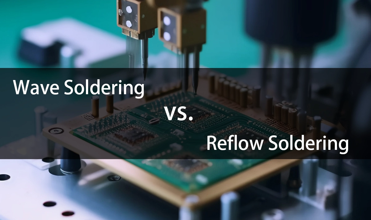
Wave Soldering vs. Reflow Soldering
Process Comparison
Wave soldering involves moving the PCB over a wave of molten solder to join through-hole leads in one pass—ideal for high-throughput. In contrast, reflow soldering uses solder paste and a temperature-controlled oven to bond surface-mount or THR components with precision, offering better control for compact and complex assemblies.Equipment and Throughput
Wave soldering setups focus on speed and repeatability, using conveyor systems, flux units, and solderpots designed for large batches. Reflow soldering relies on reflow ovens, stencils, and pick-and-place machines, supporting high-density layouts and finer pitch components—common in consumer electronics and telecom gear.Component Compatibility
Wave soldering supports traditional through-hole parts. Reflow is optimized for SMT and THR components. LINK-PP’s product lines, including THT RJ45 Connectors, SMT LAN Transformers, and THR RJ45, are designed to match each soldering method.Cost and Quality
Wave soldering generally offers lower unit costs for bulk production, while reflow soldering enables better precision and reliability—especially critical for multi-layer PCBs. Both methods deliver high quality when well optimized.Application Fit
Use wave soldering for industrial boards with robust connectors. Use reflow for dense, double-sided boards where precision and signal integrity are key.
Pros and Cons
Pros of Wave Soldering:
Fast soldering process for high-volume production
Lower cost per board in bulk manufacturing
Reliable joints for through-hole components
Simple maintenance with fewer moving parts
Quick setup and easy operation
Cons of Wave Soldering:
Limited flexibility for complex or double-sided boards
Not suitable for fine-pitch or surface-mount devices
May require extra steps for mixed-technology assemblies
Careful temperature control needed to avoid defects
Tip: Use wave soldering when you want speed and cost savings for traditional PCB designs.
Pros of Reflow Soldering:
Excellent for surface-mount and fine-pitch components
High flexibility for different board designs
Strong quality control with real-time monitoring
Supports double-sided and high-density assemblies
Cons of Reflow Soldering:
Higher equipment and maintenance costs
Requires skilled setup and process management
Slower for very large production runs
Note: Choose reflow soldering when you need flexibility and precision for advanced electronics.
Choosing a Method
Factors to Consider
When you select a soldering process for your pcb assembly, you need to look at several important factors. Each method offers unique strengths for different situations. You want to match your choice to your product needs and your production goals.
Component Type: If your board uses mostly through-hole parts, you should consider wave soldering. For boards with many surface-mount devices, reflow soldering works better.
Board Complexity: Simple, single-sided boards fit well with wave soldering. If your design has fine-pitch parts or double-sided layouts, reflow soldering gives you more control.
Production Volume: High-volume production lines benefit from the speed of wave soldering. For smaller batches or prototypes, reflow soldering offers flexibility.
Quality Requirements: If you need precise joints and low defect rates, reflow soldering helps you meet strict standards. Wave soldering provides strong joints for traditional designs.
Cost and Equipment: You must think about your budget. Wave soldering often costs less for large runs. Reflow soldering may require more investment in equipment, but it supports advanced designs.
Tip: Always review your pcb assembly layout and your component mix before you decide. The right soldering process improves your production results.
You see that wave soldering works best for high-volume, through-hole assemblies. Reflow soldering fits complex, surface-mount projects. Each soldering process offers unique strengths. Review your design and production goals before you choose.
Careful selection of your soldering method leads to better results and fewer defects.
FAQ
Q1: What’s the main difference between wave soldering and reflow soldering?
A: Wave soldering is typically used for through-hole components and involves passing the PCB over a wave of molten solder. Reflow soldering is used for surface-mount and THR components, bonding them by melting solder paste in a reflow oven.
Q2: Can I use reflow soldering for through-hole connectors?
A: Yes, if the connectors are THR (Through-Hole Reflow) compatible. LINK-PP offers THR RJ45 connectors designed specifically to withstand the high temperatures of reflow ovens.
Q3: Which method is better for high-density or double-sided boards?
A: Reflow soldering is preferred for high-density layouts and double-sided assemblies because it offers better precision and supports smaller components.
Q4: Which process is more cost-effective for mass production?
A: Wave soldering generally has lower unit costs for large batches of through-hole components. Reflow soldering may cost more upfront but is better for complex, compact designs.
Q5: Are LINK-PP products compatible with both soldering methods?
A: Yes. LINK-PP offers standard THT RJ45 connectors for wave soldering, SMT connectors for reflow, and THR variants that support reflow with through-hole mounting.