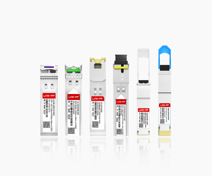
In the high-speed backbone of modern networks, optical transceivers (also known as fiber optic modules or simply optical modules) are indispensable workhorses. These compact devices convert electrical signals to optical signals and vice versa, enabling data transmission over fiber optic cables. While generally reliable, failures do occur, leading to frustrating downtime, performance degradation, and costly troubleshooting. Understanding the most common failure modes of optical transceivers is crucial for network engineers and IT professionals to maintain optimal network health. This guide explores these frequent issues and offers practical solutions, highlighting how quality products like LINK-PP optical transceivers can mitigate risks.
➤ Physical Connector Damage and Contamination (The Silent Killer)
The Problem: The fiber optic connector ferrule (the precision ceramic or metal tip) is extremely susceptible to microscopic scratches, cracks, or contamination (dust, oils, fingerprints). Even tiny imperfections scatter or block light, causing signal loss (attenuation), errors (BER increase), or complete link failure.
Symptoms: Intermittent connectivity, high error rates, reduced link distance capability, complete link failure. Often manifests as "flapping" links.
Prevention & Solution:
Always use protective caps when transceivers or fiber cables are not connected.
Inspect before connecting: Use a fiber optic inspection microscope to check ferrules for contamination or damage. This is the single most effective preventative step!
Clean properly: Use approved, lint-free wipes and optical-grade cleaning solution or cassette cleaners. Never use compressed air alone.
Handle with care: Avoid touching ferrules; grip connector bodies.
➤ Degraded or Failing Laser/Photo-Detector (The Heart Falters)
The Problem: The laser diode (Tx) or photodetector (Rx) within the module can degrade over time or fail prematurely. Causes include manufacturing defects, excessive operating temperature, voltage spikes, or simply reaching end-of-life.
Symptoms: Gradual increase in Bit Error Rate (BER), reduced optical power output (Tx), decreased receiver sensitivity (Rx), complete loss of light transmission or reception. Often causes intermittent issues before total failure.
Prevention & Solution:
Monitor DOM/DDM Data: Utilize Digital Optical Monitoring (DOM) or Digital Diagnostics Monitoring (DDM) available on most modern optical transceivers to track Tx power, Rx power, temperature, and supply voltage. Establish baselines and alert thresholds.
Ensure proper ventilation: Prevent modules from overheating. Maintain clean airflow in chassis.
Use quality power supplies: Protect against electrical surges and noise.
Source from reputable vendors: High-quality components and rigorous testing, like those used in LINK-PP transceivers, significantly reduce early failure rates.
➤ Compatibility and Configuration Issues (It Should Work, But Doesn't)
The Problem: The transceiver may be physically compatible (e.g., SFP+ form factor) but fail to link due to:
Firmware/Coding Mismatch: The host device (switch, router, NIC) rejects the module due to unrecognized or incorrect EEPROM data.
Speed/Duplex Mismatch: Incorrect port configuration settings on the host device.
Unsupported Features: The host doesn't support specific features enabled on the module (e.g., FEC).
Symptoms: Module is not recognized by the host device, link fails to come up despite good physical connections and fiber, unstable link at lower speeds.
Prevention & Solution:
Verify compatibility: Consult the equipment vendor's compatibility list (MCL/VLL). Reputable third-party manufacturers like LINK-PP rigorously test modules against major OEM platforms (Cisco, Juniper, Arista, HPE, etc.).
Check configuration: Ensure host port speed, duplex, and FEC settings match the module and link partner requirements.
Consider "Coding" Services: Some vendors offer modules pre-programmed for specific OEM environments. LINK-PP provides guaranteed compatibility coding for major platforms.
➤ Excessive Link Loss and Fiber Issues (The Path is Blocked)
The Problem: While not always the transceiver's fault, the optical link loss exceeds the module's budget. Causes include:
Dirty or damaged connectors.
Poorly mated connectors (angular misalignment, under/over insertion).
Damaged, kinked, or bent fiber optic cables (exceeding bend radius).
Too long fiber runs exceeding the module's specified distance.
High-splice loss or too many connectors in the path.
Symptoms: Intermittent connectivity, high error rates, reduced operational distance, link instability. DOM data will show low Rx power.
Prevention & Solution:
Measure Link Loss: Use an Optical Loss Test Set (OLTS) to certify fiber plant loss before deploying transceivers. Ensure loss is within the module's budget with margin.
Inspect & Clean: Always!
Check Fiber Integrity: Visually inspect cables for damage; use an OTDR for fault location if needed.
Use Appropriate Modules: Select modules (like the LINK-PP LS-SM3110-10C for 10km or LINK-PP LQ-LW100-LR4C for 10km 100G) matched to the actual required distance. Don't over-spec unnecessarily, but ensure sufficient headroom.
➤ Electrical Interface/ESD Damage (The Shock)
The Problem: Damage to the electrical contacts (gold fingers) or internal circuitry can occur from:
Electrostatic Discharge (ESD): Handling modules without proper ESD precautions (wrist straps, mats).
Physical Damage: Bent or broken pins during insertion/removal.
Hot-Swapping Issues: While many support hot-swap, power surges or improper sequencing can sometimes cause issues.
Symptoms: Module not detected by host, erratic behavior, complete failure. Physical inspection may reveal damaged contacts.
Prevention & Solution:
Strict ESD Protocols: Always handle modules in an ESD-safe environment using wrist straps and mats.
Careful Insertion/Removal: Ensure proper alignment; use manufacturer-recommended tools if required (e.g., SFP extractor). Avoid forcing modules.
Follow Hot-Swap Procedures: Power down ports if possible/advised; insert/remove modules smoothly.
➤ Environmental Stress (Heat is the Enemy)
The Problem: Optical transceivers generate heat. Operating consistently above their specified maximum temperature (often 70°C case temp) accelerates aging, degrades laser performance, and shortens lifespan. High humidity can also cause corrosion.
Symptoms: Increased BER, unstable links, reduced output power, premature failure. DOM data shows high temperature.
Prevention & Solution:
Ensure Adequate Airflow: Maintain clean air filters, avoid blocking vents, ensure proper spacing between devices. Use chassis with sufficient cooling capacity.
Monitor Temperatures: Utilize DOM/DDM to track module temperature. Set up alerts.
Consider Operating Environment: Avoid installing network gear in non-climatically controlled spaces prone to excessive heat.
➤ Quick Reference: Common Optical Transceiver Failures & Actions
Failure Cause | Primary Symptoms | Key Diagnostic Tools | Immediate Actions & Prevention |
|---|---|---|---|
Connector Damage/Dirt | Intermittency, High Errors, Link Down | Inspection Microscope, Visual Check | INSPECT & CLEAN! Use caps, proper handling. |
Laser/Detector Failure | Gradual BER Increase, Low Power, No Light | DOM/DDM (Tx/Rx Power), BER Testers | Monitor DOM, ensure cooling, replace module. Source quality (e.g., LINK-PP). |
Compatibility Issues | Module Not Detected, Link Won't Come Up | Host Logs, Compatibility Lists | Verify MCL/VLL (Use LINK-PP's compatibility guarantee), check host port config. |
Excessive Link Loss | Low Rx Power, Errors, Short Distance | OLTS, OTDR, DOM (Rx Power), Visual Check | Certify fiber loss, inspect/clean connectors/cables, ensure within module budget. |
ESD/Electrical Damage | Module Not Detected, Physical Damage | Visual Inspection, Host Detection | Strict ESD Procedures! Careful handling. Avoid hot-swap if unsure. |
Overheating | High BER, Instability, High Temp (DOM) | DOM/DDM (Temperature) | Improve airflow, clean vents/filters, monitor temps, ensure ambient within spec. |
➤ Diagnosing and Troubleshooting Optical Transceiver Failures:
Check the Obvious: Is the module seated correctly? Are fiber cables securely connected? Are the correct ports cabled (Tx to Rx)?
Inspect & Clean Connectors: Always the first technical step. Use a microscope.
Swap Components (Methodically):
Swap fiber cables between known-good ports.
Swap transceivers between known-good ports.
Move suspect transceiver/cable to a different known-good port.
Isolate whether the issue follows the module, cable, or port.
Leverage DOM/DDM Data: This is invaluable. Check:
Tx Power: Is it within specified range (High/Low Alarm/Warning thresholds)?
Rx Power: Is it within specified range and sufficiently above the receiver sensitivity?
Temperature: Is it within operating range?
Voltage: Is supply voltage normal?
Check Host Device Logs: Look for error messages related to the specific port or module (e.g., "module disabled," "unsupported transceiver," "LOS - Loss of Signal," "LOL - Loss of Lock").
Verify Compatibility: Double-check the module is listed as compatible for the specific host device model and software version.
Measure Link Loss: If Rx power is low and cleaning didn't help, use an OLTS to measure end-to-end loss.
➤ The LINK-PP Advantage: Minimizing Failure Risks

Choosing high-quality optical transceivers is paramount for network reliability. LINK-PP modules are engineered to withstand common failure points:
Rigorous Component Selection: Using Tier-1 lasers and detectors for longevity.
Stringent Testing: 100% tested for performance parameters (power, sensitivity, extinction ratio, BER) and DOM accuracy over full temperature range.
Superior Contamination Control: Manufactured and handled in controlled environments.
Robust ESD Protection: Enhanced circuitry to safeguard against electrostatic discharge.
Guaranteed Compatibility: Extensive testing against major OEM platforms ensures seamless integration, reducing configuration headaches.
Comprehensive DOM/DDM Support: Provides essential data for proactive monitoring and troubleshooting.
Models You Can Trust: Reliable performers like LINK-PP's LS-MM8510-S3C, LS-SM3125-10C, LQ-M85100-SR4C, and LQD-CW400-FR4C are built to deliver.
➤ Conclusion
Understanding the common failure modes of optical transceivers empowers network professionals to proactively prevent issues and rapidly troubleshoot problems when they arise. By prioritizing meticulous cleaning, careful handling, environmental control, DOM monitoring, and – critically – sourcing high-quality, compatible modules like those from LINK-PP, organizations can significantly reduce downtime, ensure optimal network performance, and maximize the return on their optical infrastructure investment. Remember, prevention and quality are always more cost-effective than reactive repairs.


