
Introduction
In modern high-speed electronics and communication devices, Electromagnetic Compatibility (EMC) is a critical factor that ensures system stability and reliable performance. During PCB design, understanding and managing Electromagnetic Interference (EMI), Electromagnetic Susceptibility (EMS), and EMC itself is essential to ensure products pass certification and operate flawlessly.
This article provides a detailed overview of these three concepts, their importance in PCB design, and practical applications. We will also explore real-world product examples, such as RJ45 ICMs, to illustrate effective EMC design strategies.
EMC, EMS, and EMI Basics
1. Electromagnetic Interference (EMI)
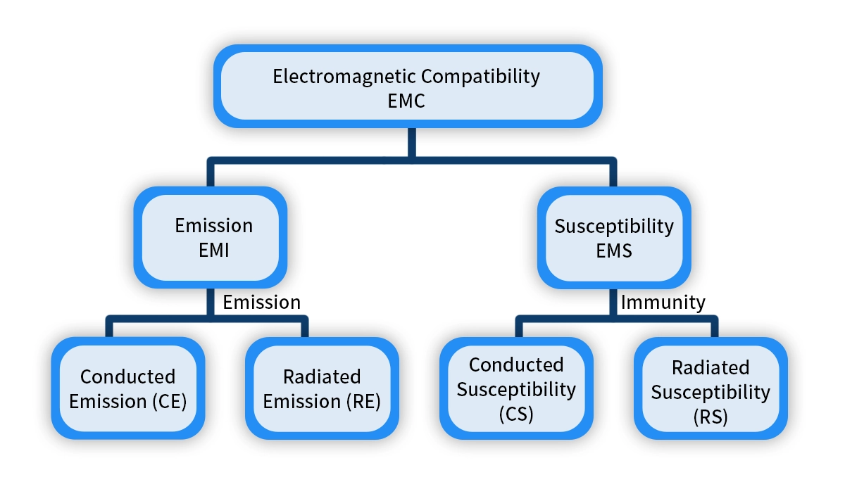
EMI refers to unwanted electromagnetic energy generated by a PCB or electronic device. This interference can propagate via conduction or radiation and disrupt the normal operation of nearby electronics. EMI can originate from both internal circuit elements (e.g., switching regulators, clock lines) and external sources such as nearby industrial equipment, radio transmitters, or electrostatic discharges. Effective EMC design considers both emission from the device and immunity to external sources.
Conducted EMI: Travels through power or signal lines.
Radiated EMI: Propagates as electromagnetic waves through space.
2. Electromagnetic Susceptibility (EMS)
EMS is often interpreted as the counterpart to immunity in EMC testing. While not a formal standard term, it is used to describe a device’s tendency to suffer performance issues when exposed to electromagnetic disturbances. In regulatory language, this concept is formally addressed through immunity testing defined in standards like IEC 61000-4-x.
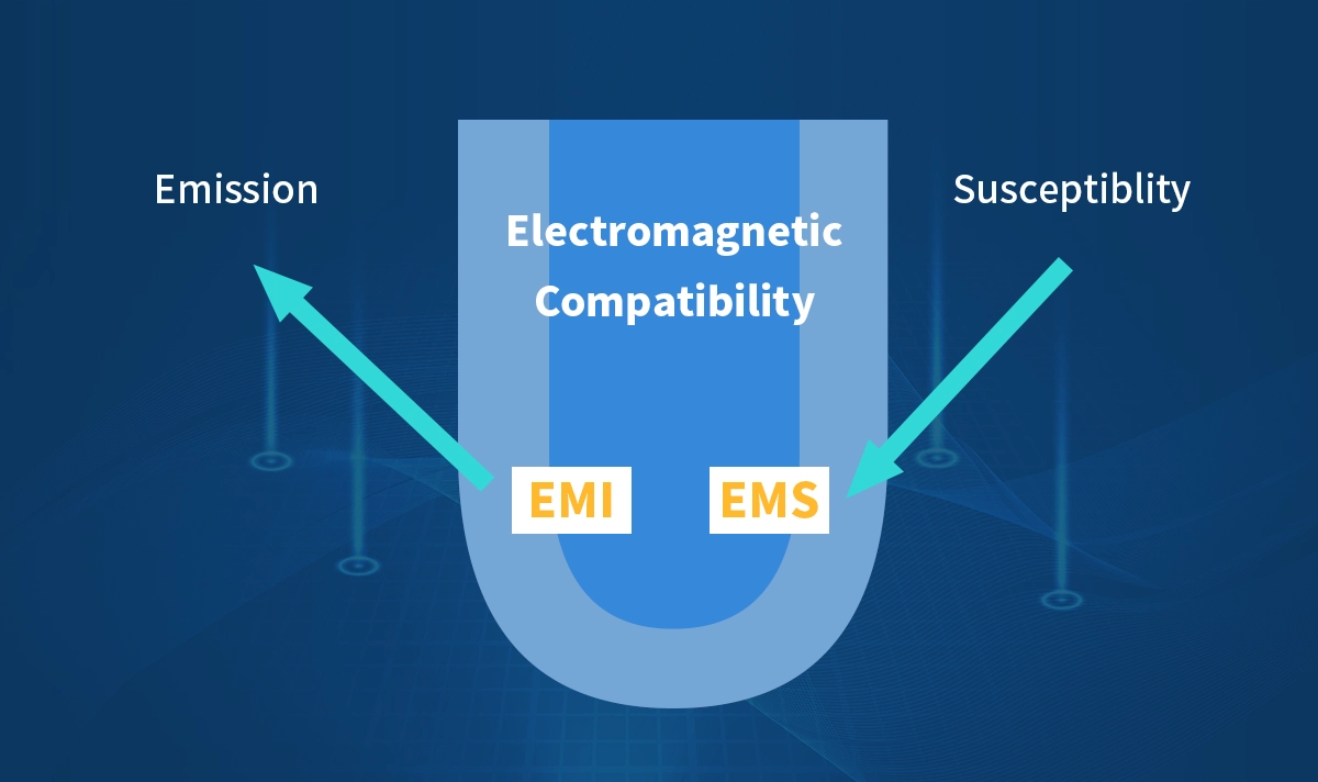
3. Electromagnetic Compatibility (EMC)
EMC is the ability of an electronic device to operate correctly in its electromagnetic environment without emitting excessive EMI or suffering from external EMI. EMC encompasses two key aspects:
Emission control: Minimizing the device’s EMI emissions.
Immunity design: Strengthening the device’s resistance to incoming EMI.
EMC, EMS, EMI: Key Differences
Term | Role | Description |
|---|---|---|
EMI | Interference source | The electromagnetic noise generated by a device or environment. |
EMS | Sensitivity | How vulnerable a device is to external electromagnetic noise. |
EMC | Compatibility ability | The device’s capability to limit its EMI emissions and resist external EMI. |
PCB Design Strategies for EMC, EMS, and EMI
Reducing EMI
Filtering components: Use capacitors, inductors, and ferrite beads to suppress conducted and radiated noise.
Shielding techniques: Employ metal shields and grounded enclosures to block radiated EMI.
Optimized layout: Shorten high-frequency signal loops, separate noisy and sensitive circuits, and implement solid ground planes.
Controlled routing: Manage impedance and minimize common-mode currents.
Enhancing EMS
Protective components: Implement surge protectors, transient voltage suppressors (TVS), and ESD protection devices.
Power supply design: Ensure clean and stable power rails with proper filtering.
Hardware and software synergy: Use hardware filters combined with software interrupt handling to improve immunity.
Meeting EMC Standards
Follow international regulations such as FCC Part 15, CISPR, and IEC 61000 series.
Incorporate EMC considerations early in the design phase to reduce costly redesigns.
Balance emission reduction and immunity to achieve compliance and reliable operation.
For example, IEC 61000-4-2 covers electrostatic discharge (ESD) immunity testing, while IEC 61000-4-3 addresses radiated RF immunity. FCC Part 15 limits EMI emission for devices sold in the U.S., primarily applying to unintentional radiators like digital devices.
EMC Testing
EMC testing procedures verify that your device meets emission and immunity requirements. You need to test both how much electromagnetic interference your device emits and how well it withstands external interference.
The standard EMC testing process includes:
Place your device in a controlled environment, such as an anechoic chamber.
Measure electromagnetic emissions across a wide frequency range.
Expose your device to external electromagnetic fields to test immunity.
Simulate real-world electromagnetic conditions to ensure reliability.
Compare results to regulatory standards like FCC Part 15 and the EU EMC Directive.
Certify devices that pass, allowing market entry with FCC authorization or CE marking.
Use additional standards such as IEC and CISPR for specific product categories.
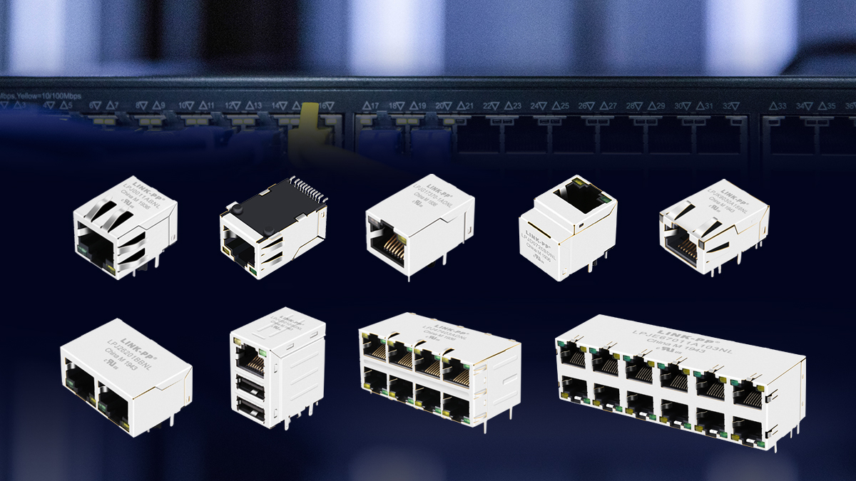
Case Study: EMC Design Highlights of LINK-PP RJ45 Connectors
Shielding optimization: Multi-layer metal shields effectively reduce radiated EMI.
Integrated magnetics: Built-in transformers minimize common-mode noise and improve signal integrity.
PCB grounding: Multi-layer PCB with continuous ground planes to optimize return paths.
Filtering and isolation: Strategic placement of ferrite beads and capacitors to reduce conducted noise.
This design not only passes stringent EMI emission tests but also exhibits excellent EMS immunity, meeting industrial and commercial EMC standards to ensure stable device operation.
Conclusion
EMI, EMS, and EMC are fundamental concepts in PCB design and electronics manufacturing. Understanding their relationships and implementing effective design and testing strategies can prevent electromagnetic disturbances and enhance device reliability.
By combining filtering, shielding, layout optimization, and high-quality component integration—as demonstrated by LINK-PP’s RJ45 ICM modules—engineers can ensure products meet international EMC standards and deliver high performance.
FAQ
What is the main goal of electromagnetic compatibility in electronic devices?
You want your electronic devices to work together without causing or suffering from electromagnetic interference. Electromagnetic compatibility ensures reliable operation in real-world environments.
How can you reduce the effects of EMI in your designs?
You can use shielding, grounding, and EMI filters. These methods help block electromagnetic disturbances and lower susceptibility. Good layout and proper testing also improve compatibility.
Why is EMC testing important before selling a product?
You need EMC testing to check if your device meets EMC standards and regulations. Passing EMC compliance testing helps you avoid interference issues and ensures safe, reliable products.
See Also
Understanding The Causes And Effects Of EMI Interference
A Comprehensive Guide To Electromagnetic Compatibility Explained
Essential Facts Everyone Should Understand About Power Over Ethernet


