


LINK-PP RJ45 Connectors part numbers follow a well-structured naming convention designed to clearly communicate key product characteristics at a glance. Each segment of the part number represents specific technical information—including the product series, connector type, schematic, mechanical design, LED configuration, and RoHS compliance. This standardized format ensures consistency across the LINK-PP product line and helps engineers, buyers, and distributors easily identify and compare specifications.
🔢 Part Number Format:
The LINK-PP RJ45 Connector Series follows a structured naming convention to precisely identify product specifications. The format is:
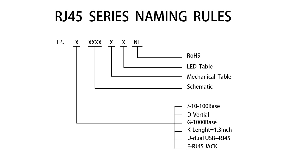
LPJ / X / XXXX / X / X / NL
Below is a detailed breakdown of each segment:
1. First Part: LPJ — Series Identifier
LPJ refers to the LINK-PP RJ45 Connector Series, representing the brand and product family.
2. Second Part: X — Type Code
This code indicates the product type or form factor:
/: 10/100Base-T Ethernet SeriesD: Vertical TypeG: 1000Base-T (Gigabit Ethernet) SeriesK: Length = 1.3 inchU: Dual (RJ45 + USB Combo) SeriesE: RJ45 Jack (Non-integrated magnetics)
3. Third Part: XXXX — Schematic Code
A 4-digit code representing the internal schematic circuit.
🔍 For detailed schematics, please refer to the product datasheets or contact LINK-PP directly.
4. Fourth Part: X — Mechanical Code
This letter defines the mechanical structure, especially regarding LEDs and EMI fingers:
Code | Configuration |
|---|---|
| With LED and EMI-Finger |
| With LED and Non EMI-Finger |
| Without LED but with EMI-Finger |
| Without LED and EMI-Finger |
| With LED and EMI-Finger (L=4.9mm) |
| With LED and No EMI-Finger (L=4.9mm) |
| With LED and EMI-Finger (L=4.06mm) |
| With LED and No EMI-Finger (L=4.06mm) |
5. Fifth Part: X — LED Code
Specifies LEDs colors and polarity using a code (letter or number):
💡 Complete LED Color Table
Code | Left LED Color | Right LED Color |
|---|---|---|
A | Y | G |
B | G | Y |
C | G | G |
D | Y | G |
E | G | Y |
F | G | G |
G | Y | G |
H | G | Y |
W | G | G |
Z | G | G |
28 | G | Y |
42 | Y | G |
4 | G/Y | G/Y |
31 | G/O | G/O |
47 | Y/G | Y/G |
65 | G/R | G/R |
Q | Y | G/O |
U | G | Y/G |
29 | G | O/G |
35 | Y/G | Y |
I | Y/G | G |
O | O/G | Y |
53 | O/G | G |
64 | G/O | Y |
97 | Y/G | G |
98 | O/G | Y |
⚠️ Note: Same LED colors may have different internal polarity.
LED Color Legend: Y – Yellow, G – Green, O – Orange, R – Red.
6. Sixth Part: NL — RoHS Compliance
NL indicates that the product is RoHS compliant, adhering to environmental safety standards.
📘 Product Naming Examples
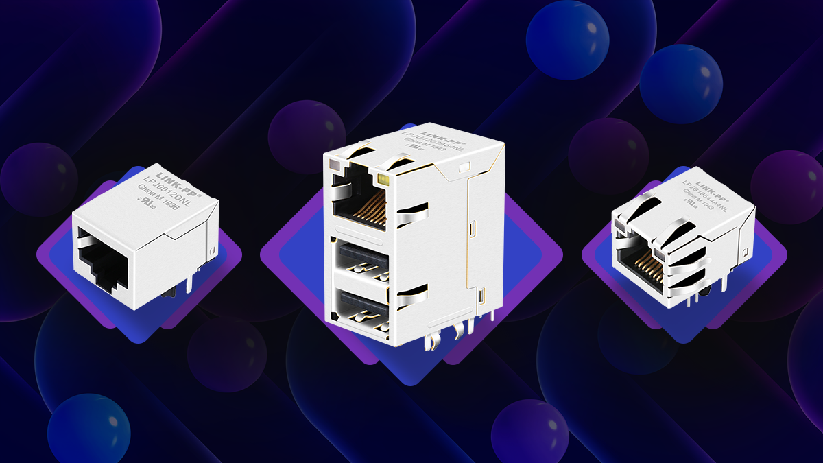
✅ Example 1: LPJG16544A4NL
1000 Base-T Single Port RJ45 PCB Connector with Integrated Magnetic Tab Up Green&Yellow/Green&Yellow LEDs
LPJ – LINK-PP RJ45 Series
G – 1000Base-T Gigabit Series
1654 – Schematic (see drawing)
A – With LEDs and EMI Finger
4 – LED Left: Green/Yellow, Right: Green/Yellow
NL – RoHS Compliant
✅ Example 2: LPJU4203A64NL
1000 Base-T RJ45 Magjack With Dual USB Combo Tab Up Green&Orange/Yellow LEDs
LPJ – LINK-PP RJ45 Series
U – Dual USB + RJ45 Combo
4203 – Schematic (see drawing)
A – With LEDs and EMI Finger
64 – LED Left: Green/Orange, Right: Yellow
NL – RoHS Compliant
✅ Example 3: LPJ0012DNL
10/100 Base-T RJ45 Connenctor Tab Down Without LED and EMI Fingers for Smart Home
LPJ – LINK-PP RJ45 Series
/ – 10/100Base-T Series
0012 – Schematic (see drawing)
D – No LED, No EMI Finger
/ – No LED
NL – RoHS Compliant
Summary
The naming convention LPJ / X / XXXX / X / X / NL ensures precise identification of:
Product line (
LPJ),Connector type (
/,D,G, etc.),Schematic design (
XXXX),Mechanical features (
A,B,C, etc.),LED configuration (
A,B,28, etc.),RoHS compliance (
NL).


