
▶ Introduction
In optical communication, every fraction of a decibel can decide whether a link runs flawlessly or fails under load. One of the most important parameters is insertion loss (IL) — the amount of optical power lost when light travels through a component, connector, or fiber link. Engineers consider insertion loss a cornerstone measurement when calculating link budgets, testing fiber installations, and selecting optical transceivers.
This article explains what insertion loss is, how it is measured, what typical values look like, and why it matters for the performance of optical modules such as those supplied by LINK-PP.
▶ What is “Optical Transceiver Insertion Loss”?
Definition in simple terms
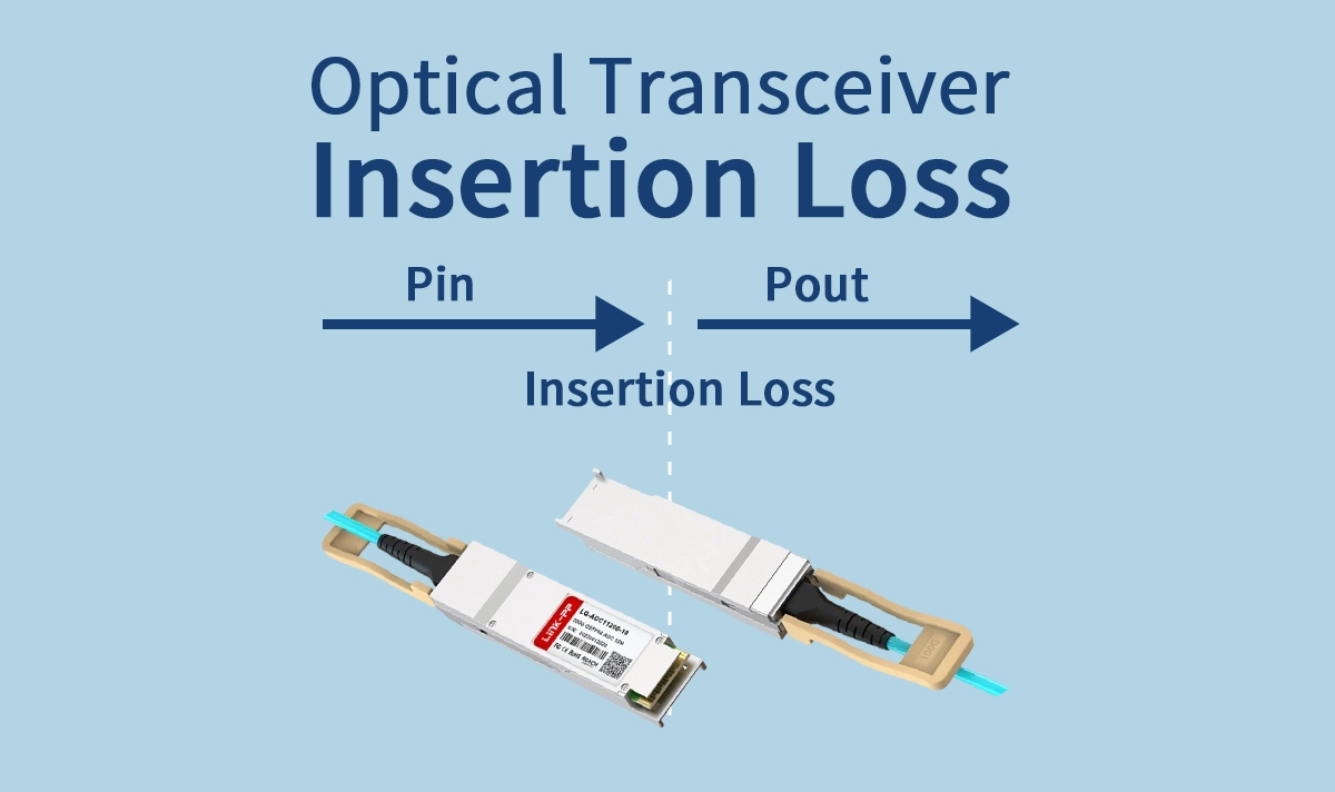
Insertion loss is the reduction in signal power between the input and the output of a component or link. It is always expressed in decibels (dB). Lower IL means more light reaches the receiver.
Mathematically:
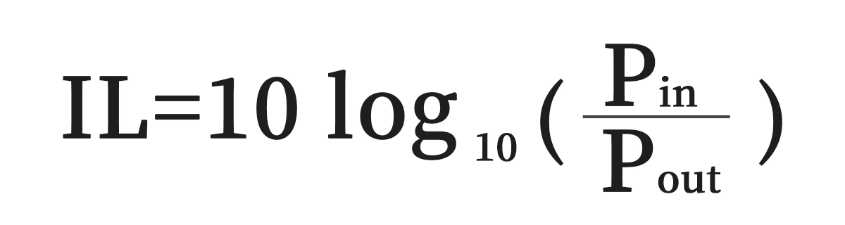
Where:
Pin = input optical power
Pout = output optical power
If you launch –2 dBm into a fiber and receive –2.5 dBm at the far end, the insertion loss is 0.5 dB.
Why IL matters
Because optical receivers require a certain minimum input power to operate correctly, excess IL directly reduces system margin and can cause the receiver to fall below sensitivity threshold. This leads to higher bit-error rates (BER) or even dropped connections.
▶ Causes of Insertion Loss
Insertion loss is inevitable, but it can be minimized with good design and maintenance. Major contributors include:
Connector mating loss — Small gaps, misalignment, or dirt between two fiber connectors increase loss.
Fiber attenuation — Even high-quality single-mode fiber has inherent attenuation (e.g., ~0.35 dB/km at 1310 nm, ~0.2 dB/km at 1550 nm).
Splice loss — Mechanical or fusion splices typically add 0.05–0.3 dB.
Bending loss — Sharp bends or microbends cause signal leakage.
Internal losses in modules — Optical transceivers have built-in lenses and interfaces that add small IL values.
▶ How to Measure Insertion Loss
OLTS (Optical Loss Test Set)
The most accurate way to measure IL is with an OLTS: a calibrated light source at one end of the link and a power meter at the other. This is the standard Tier-1 certification test in fiber optics.
Steps:
Connect the source and meter with a known reference cable.
Measure reference power (Pin).
Connect the fiber link under test.
Measure output power (Pout).
Calculate IL = 10·log10(Pin/Pout).
OTDR (Optical Time Domain Reflectometer)
An OTDR can also estimate IL, but it is mainly used for fault location. For acceptance testing, OLTS is preferred.
Field testing tips
Always clean connectors before testing — contamination is the #1 cause of excess loss.
Test in both directions (A→B and B→A) and average the results.
Use high-quality reference cables with known low IL.
▶ Typical Insertion Loss Values
Typical IL numbers help engineers design link budgets:
Single connector: 0.1–0.5 dB (good polish and clean).
Mechanical splice: 0.2–0.5 dB.
Fusion splice: 0.05–0.1 dB.
Single-mode fiber attenuation: 0.35 dB/km at 1310 nm, 0.2 dB/km at 1550 nm.
Multimode fiber attenuation: 3.0 dB/km at 850 nm, 1.0 dB/km at 1300 nm.
For example, a 10 km single-mode link at 1550 nm with two connectors and two splices might have total IL ≈ 0.2 × 10 + 0.3 + 0.1 = 2.4 dB.
▶ Insertion Loss in Link Budget Calculations
The link budget is the difference between transmitter output power and receiver sensitivity, adjusted for IL and margin.
Example:
Transmitter (Tx) power: 0 dBm
Receiver (Rx) sensitivity: –14 dBm
Available budget = 14 dB
If IL = 10 dB, margin = 4 dB → acceptable.
If IL = 15 dB, margin = –1 dB → link fails.
This shows why even fractions of a dB matter.
▶ Impact on Optical Transceivers
Insertion loss impacts optical modules in three main ways:
Reduced margin: High IL reduces available system margin, leaving the link vulnerable to aging or temperature changes.
Higher BER: Lower signal-to-noise ratio at the receiver means more bit errors.
Shortened reach: A module rated for 40 km may only reach 30 km if IL exceeds assumptions.
For example, LINK-PP’s LS-CW3110-40I optical transceiver is designed for 40 km 10G transmission. If deployed with excess IL (dirty connectors, poor splices), its effective reach will shrink. Checking IL is therefore part of ensuring datasheet-level performance.
▶ How to Minimize Insertion Loss
Clean connectors before each use with lint-free wipes and isopropyl alcohol.
Inspect end-faces with a fiber scope.
Use fusion splicing instead of mechanical splicing whenever possible.
Avoid sharp bends — respect fiber bend radius.
Choose quality components — modules, connectors, and patch cords with guaranteed IL specs.
▶ Where LINK-PP helps
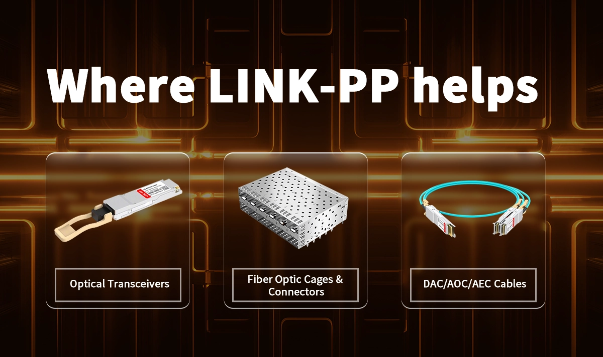
If you’re designing or operating links in the 1G–800G range, LINK-PP provides modules and connectivity designed for compatibility, performance, and smooth qualification:
Optical transceivers: SFP/SFP+, SFP28, QSFP28, QSFP-DD, OSFP families aligned with IEEE Ethernet optics. See our overview of why enterprises choose our modules in Why choose LINK-PP fiber optical modules.
Connectors and assemblies: LC duplex and MPO/MTP-compatible connectivity with low-loss options to protect your budget. For foundational connector context, see Common Fiber Connector Types in Optical Transceivers.
Evaluation made easy: Request free samples and get engineering support to validate IL and link budgets in your environment—see sample/support CTAs on our store pages like the LINK-PP 1G SFP catalog page.
▶ Quick FAQ
Q1: What is an acceptable insertion loss value per connector?
A: For high-quality connectors, <0.3 dB is typical.
Q2: How often should IL be tested?
A: At installation and after any major maintenance. Critical links may be retested during scheduled audits.
Q3: Can insertion loss be reduced after installation?
A: Often yes — cleaning connectors or re-terminating high-loss splices can lower IL.
▶ Conclusion
Insertion loss may seem like a small number, but in high-speed optical networks every fraction of a decibel counts. Proper design, testing, and maintenance are essential to ensure reliable performance.
For engineers deploying LINK-PP optical transceivers, checking insertion loss is a critical step in validating real-world performance.
By understanding insertion loss, testing it correctly, and minimizing it in practice, network operators can build links that are reliable, high-performing, and ready for the future.


