

In the intricate world of fiber optic networks, every connection point matters. The humble connector, specifically the fiber connector polish type, plays a critical role in signal integrity, loss, and overall network reliability. Understanding the differences between PC (Physical Contact), UPC (Ultra Physical Contact), and APC (Angled Physical Contact) polishes is essential for any network designer, installer, or technician. Choosing the wrong type can lead to performance degradation, increased bit error rates (BER), and costly downtime. This guide dives deep into the technology, applications, and selection criteria for these crucial connector types.
Why Polish Matters: The Physics of Light Coupling
At the core of any fiber optic connection is the need to align two microscopic glass fibers (typically 9µm core for single-mode) with extreme precision. The goal is to maximize light transmission from one fiber to the other while minimizing two key parameters:
Insertion Loss (IL): The amount of signal power lost at the connection point (measured in dB). Lower is better.
Return Loss (RL) / Back Reflection: The amount of light reflected back towards the source (measured in dB). Higher RL values (less reflection) are better, especially for high-speed and analog signals.
The end-face geometry and surface finish of the ceramic ferrule (the part holding the fiber) directly impact IL and RL. This is where the polish type comes in.
The Contenders: PC, UPC, and APC Explained
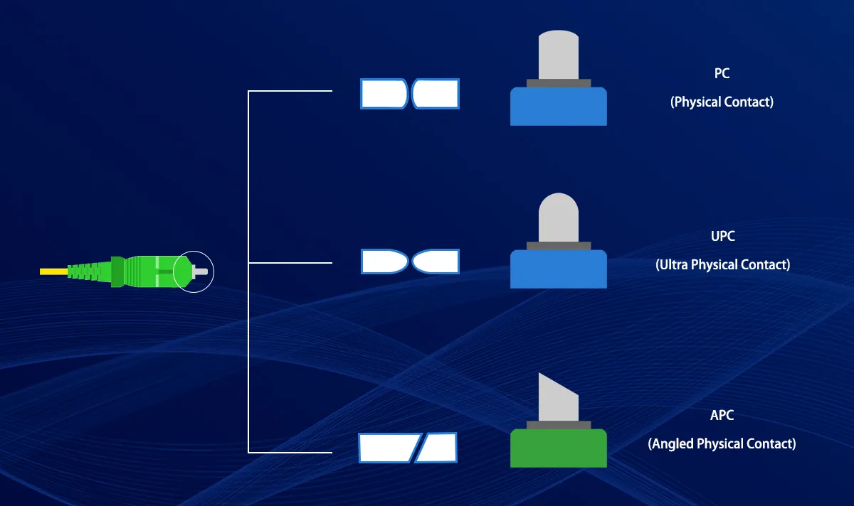
PC (Physical Contact):
Technology: Features a slightly curved (domed) end-face. This curvature ensures the fibers make contact primarily at their central cores when mated, minimizing the tiny air gap present in flat-polished connectors. The curvature helps push contaminants to the edge.
Performance:
Insertion Loss: Typically around -0.5 dB. Adequate for many legacy systems.
Return Loss: Around -30 dB to -40 dB. Significant back reflection can occur, potentially interfering with laser sources.
Applications: Largely superseded by UPC and APC in new installations. Still found in some older telecom systems, basic data links, or multimode applications where back reflection is less critical. Not recommended for modern high-speed or analog systems.
UPC (Ultra Physical Contact):
Technology: An evolution of PC. Uses an extended polishing process to achieve a finer, more spherical dome and a significantly smoother surface finish. This reduces microscopic imperfections.
Performance:
Insertion Loss: Lower than PC, typically -0.3 dB or better. Excellent for minimizing signal attenuation.
Return Loss: Improved over PC, reaching -50 dB or better. Suitable for most digital communication systems (Gigabit Ethernet, 10G, even some 25G).
Applications: The dominant choice for general-purpose single-mode and multimode applications within data centers, enterprise networks, FTTH distribution points (non-analog video), and telecom where very high RL isn't mandatory. Offers the best balance of performance and cost for many digital links. Compatible with a vast range of optical transceivers (SFP, SFP+, QSFP+, etc.).
APC (Angled Physical Contact):
Technology: Features an *8-degree angled* end-face polish combined with the ultra-fine finish of UPC. This angle is the key differentiator.
Performance:
Insertion Loss: Comparable to UPC, typically -0.3 dB or better.
Return Loss: Significantly superior, achieving -60 dB or better. The angled surface causes reflected light to be directed into the fiber's cladding, where it's absorbed instead of traveling back to the laser.
Applications: Essential for applications extremely sensitive to back reflection:
High-speed networks (40G, 100G, 400G Ethernet, CPRI/eCPRI for 5G)
RF broadband networks (CATV/HFC video transmission - analog signals are highly reflection-sensitive)
Passive Optical Networks (PON) like GPON, XGS-PON (especially the upstream path)
Coherent optical transmission systems
Any system using distributed feedback (DFB) lasers. Requires specifically designed APC compatible optical transceivers.
PC vs UPC vs APC: Critical Comparison
The table below summarizes the key differences:
Feature | PC (Physical Contact) | UPC (Ultra Physical Contact) | APC (Angled Physical Contact) |
|---|---|---|---|
End-Face | Spherical Curvature | Enhanced Spherical Curvature | 8-Degree Angle + Curvature |
Polish | Standard | Superfine | Superfine |
Insertion Loss | ~ -0.5 dB | ~ -0.3 dB or better | ~ -0.3 dB or better |
Return Loss | ~ -30 dB to -40 dB | ~ -50 dB or better | > -60 dB |
Key Strength | Basic Contact | Low Loss (Cost-Effective) | Ultra-Low Reflection |
Key Weakness | Higher Loss & Reflection | Not ideal for ultra-sensitive RF/High-Speed | Slightly Higher Cost, Incompatible with PC/UPC |
Color Code | Blue (SM), Beige (MM) | Blue (SM), Beige (MM) | Green |
Compatibility | PC, UPC (not recommended) | PC, UPC | APC Only (Mating causes damage) |
Best For | Legacy Systems, Multimode | Data Centers, Enterprise LAN, General Telecom, Digital FTTH | CATV/HFC, High-Speed (40G+), PON, RFoG, 5G Fronthaul |
Tip: Always match connector types at both ends of a fiber link to maintain optimal performance and avoid signal loss.
Key Differences
The debate of pc vs upc vs apc centers on three main factors: endface geometry, return loss, and application suitability. Each connector type offers unique advantages and limitations, making the selection process critical for network reliability.
Endface Geometry and Angle
PC and UPC connectors both feature a flat or slightly domed endface with a 0° angle. UPC connectors receive additional polishing, resulting in a smoother surface and improved performance over PC. APC connectors stand out with an 8° angled endface, which directs reflected light into the fiber cladding rather than back toward the source. This design significantly reduces back reflection.Return Loss and Insertion Loss
Industry measurements show that insertion loss remains similar across all three fiber connector types, typically around 0.3 dB. UPC connectors often achieve the lowest insertion loss due to their precise polish. However, the most significant difference appears in return loss. PC connectors provide about -40 dB, UPC improves this to -50 dB, and APC achieves -60 dB or better. The higher the return loss, the less light reflects back, which is crucial for high-performance fiber optic systems.Color Coding and Identification
Color coding simplifies identification in the field. PC connectors usually appear blue or black, UPC connectors are blue, and APC connectors are green. This visual cue helps technicians avoid mismatching connectors, which can cause excessive insertion loss and degraded signal quality.Application Suitability
PC connectors serve well in standard enterprise LANs and general telecom environments where moderate return loss suffices. UPC connectors, with their improved polish, fit digital TV, telephony, and data center applications that require lower back reflection but not the absolute minimum. APC connectors excel in high-precision optical networks, including WDM, FTTx, and RF video transmission, where even minimal back reflection can disrupt performance.Mating and Compatibility
Technicians must never mate APC connectors with PC or UPC connectors. The angled endface of APC does not align with the flat or domed surfaces of PC and UPC, leading to high insertion loss and poor return loss. Always use the same connector type on both ends of a fiber link.Performance Over Time
Industry tests confirm that APC connectors maintain their low return loss even after repeated mating cycles, provided they connect only with other APC connectors. UPC and PC connectors may experience performance degradation over time, especially if the polish quality declines.
Note: Combining both insertion loss and return loss measurements gives a more accurate assessment of connector performance. While insertion loss remains similar, the return loss difference often determines the best choice for sensitive fiber optic applications.
Choosing the Right Connector: Key Considerations
Application & Signal Type: Is it digital data? High-speed? Analog video (RF)? RF and very high-speed digital mandate APC.
Network Standard: Check your PON standard, telecom spec, or equipment manufacturer requirements. Many modern OLTs/ONUs mandate APC.
Required Performance: What are the acceptable IL and RL budgets? Pushing 100G or beyond? APC is safer.
Compatibility: Mixing APC with PC or UPC WILL DAMAGE THE CONNECTORS! Always match the polish type. APC uses distinctive green ferrules for visual identification. Ensure your optical transceiver modules match the connector type (e.g., an SFP+ with APC receptacle for green connectors).
Cost: UPC generally offers the best price/performance for standard digital. APC carries a slight premium but is non-negotiable where needed.
The LINK-PP Advantage: Your Partner in Precision Connectivity

Navigating connector specifications and ensuring compatibility with your optical transceiver inventory can be complex. At LINK-PP, we specialize in high-performance fiber optic solutions. We offer:
Expert Guidance: Our engineers can help you select the optimal PC, UPC, or APC connectors and compatible optical transceivers for your specific application, whether it's high-density data center optical transceiver deployment or robust outside plant FTTx networks.
Premium Quality Components: Reliable patch cables, pigtails, and adapters featuring precise PC, UPC, and APC polishes, manufactured to stringent standards for low loss and longevity.
Comprehensive Transceiver Solutions: A wide range of guaranteed-compatible SFP, SFP+, QSFP28 optical transceivers and more, supporting all polish types for seamless integration.
FAQ
What happens if someone mixes APC and UPC connectors?
Mismatching APC and UPC connectors causes poor alignment. This results in high insertion loss and increased back reflection. Network performance drops, and signal quality suffers. Technicians should always match connector types at both ends.
How can a technician identify connector types in the field?
Technicians use color coding for quick identification. Blue indicates UPC or PC connectors. Green always marks APC connectors. Labels on patch panels and cables also help confirm connector types.
Which connector type offers the best performance for long-distance links?
APC connectors provide the highest return loss and lowest back reflection. They perform best in long-distance, high-precision networks, such as WDM or FTTH systems.
Are PC connectors still suitable for modern networks?
PC connectors remain effective for standard enterprise LANs and general telecom applications. They offer reliable performance where moderate return loss suffices. For advanced or high-speed networks, UPC or APC connectors work better.
How often should fiber connectors be inspected or cleaned?
Technicians should inspect and clean fiber connectors before every installation or reconnection. Regular maintenance prevents contamination, reduces signal loss, and extends connector lifespan.
Tip: Always use approved cleaning tools and follow manufacturer guidelines for best results.


