


Why Soldering Method Matters for RJ45 Connectors
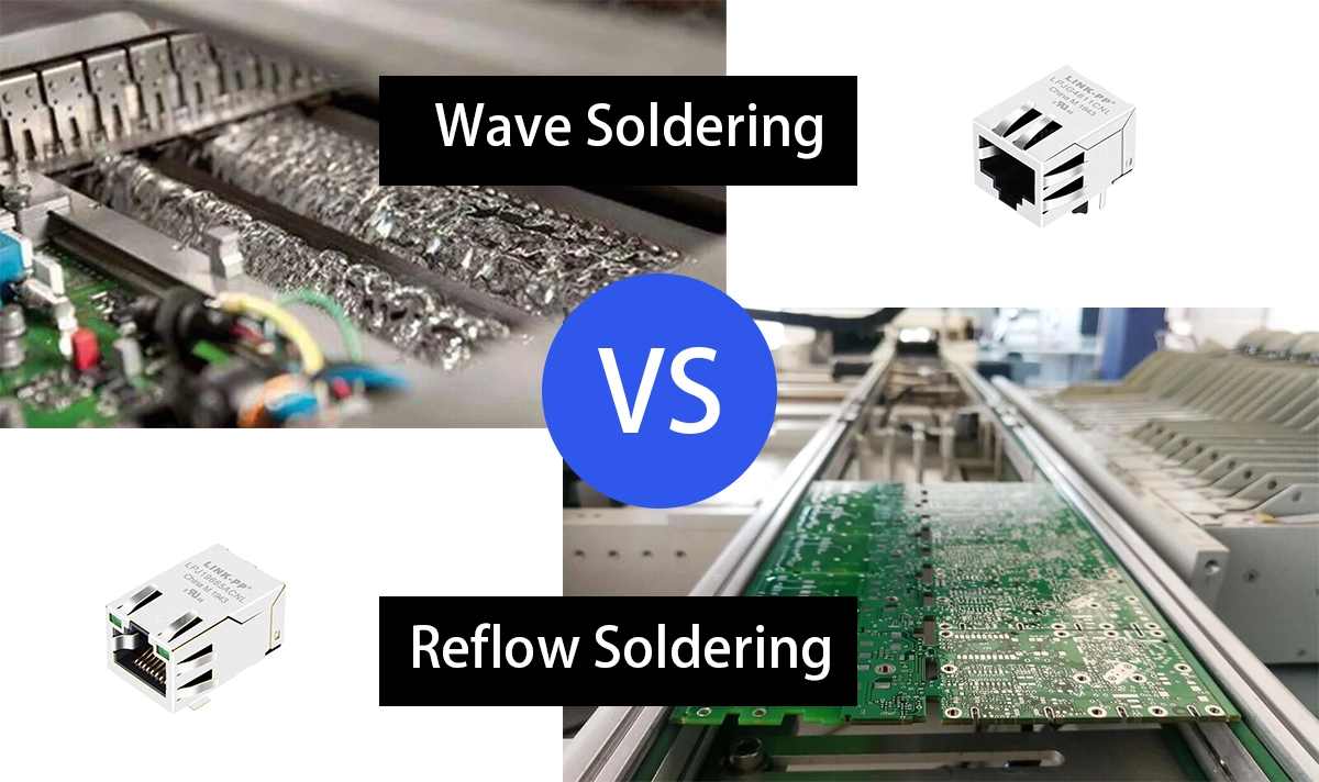
In modern electronics manufacturing, the choice between reflow soldering and wave soldering is critical—especially for components like RJ45 connectors, which are commonly used in Ethernet networking applications. These two soldering methods require different connector designs (SMT vs. THT) and have varying implications for reliability, production efficiency, and board layout.
This article outlines the key differences between reflow and wave soldering for RJ45 connectors and helps engineers select the right connector for their design and process.
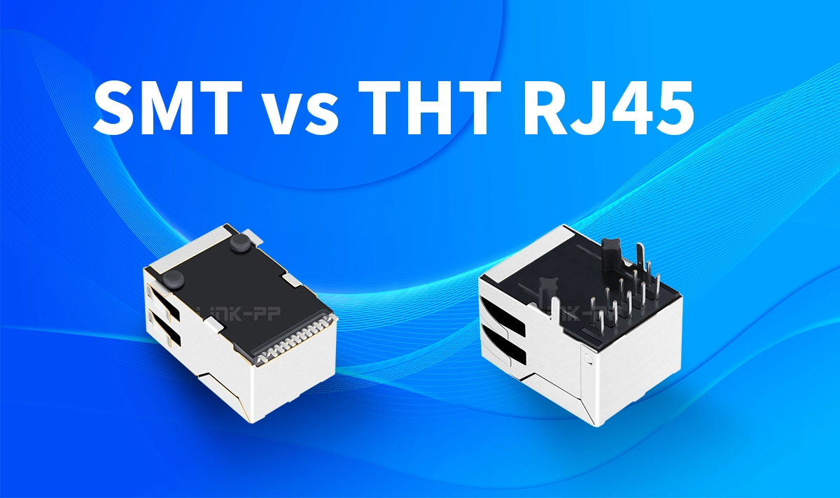
SMT vs. THT RJ45 Connectors: Basic Definitions
Type | Description | Mounting Method |
|---|---|---|
SMT (Surface Mount Technology) | RJ45 connector with surface mount terminals | Reflow soldering |
THT (Through-Hole Technology) | RJ45 connector with insertion pins | Wave soldering |
SMT RJ45 connectors are designed for automated placement on surface pads and are ideal for high-density PCBs.
THT RJ45 connectors use pins that go through holes in the PCB and offer stronger mechanical strength.
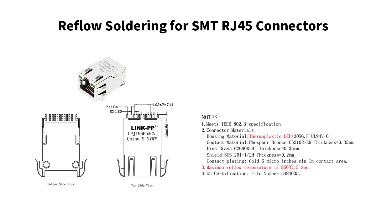
Reflow Soldering for SMT RJ45 Connectors
Process Overview:
Reflow soldering involves applying solder paste to pads, placing the connector, and heating the assembly in a controlled oven where the solder melts and reflows.
Key Characteristics:
Heating Method: Convection or infrared heating from top-down
Peak Temperature: Typically up to 240–260°C
PCB Design: Flat surface pads; no plated through-holes
Material Requirement: High-temperature thermoplastics (e.g., LCP)
Advantages:
Supports full SMT assembly line (no manual insertion)
Compatible with automated pick-and-place
Ideal for space-saving and multilayer PCBs
Considerations:
The connector housing must withstand high temperatures.
Mechanical strength is lower compared to through-hole types, so metal pegs or board locks are often used.
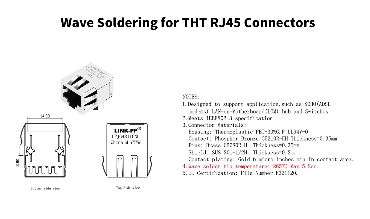
Wave Soldering for THT RJ45 Connectors
Process Overview:
In wave soldering, a PCB with inserted connectors passes over a molten solder wave, which bonds the pins to the PCB.
Key Characteristics:
Heating Method: Bottom-up contact with solder wave
Peak Temperature: Around 250°C, short exposure
PCB Design: Plated through-holes for pin insertion
Material Requirement: Sufficient heat resistance for solder contact
Advantages:
Stronger mechanical fixation due to through-hole pins
Easier to solder multiple large connectors in one pass
Lower material cost for connector body
Considerations:
May require manual pre-insertion
Less suitable for high-density boards or double-sided SMT assembly
Comparison Table: Reflow vs. Wave Soldering for RJ45 Connectors
Feature | Reflow Soldering (SMT) | Wave Soldering (THT) |
|---|---|---|
Automation Level | High (Fully automated) | Medium (Insertion often manual) |
Connector Mounting | Surface mount | Through-hole |
Mechanical Strength | Moderate (with support pins) | High (pin-through-hole) |
Temperature Tolerance | High (plastic must resist 260°C) | Moderate (localized heating) |
Assembly Cost | Higher for connector; efficient for large volumes | Lower connector cost; higher labor |
PCB Density Suitability | Excellent | Limited |
Best Practices for Selecting the Right RJ45 Connector
When choosing between SMT and THT RJ45 connectors, consider the following:
✅ Choose SMT RJ45 if:
You have a high-density PCB layout
The product is mass-produced via SMT lines
Connector height and profile are design constraints
✅ Choose THT RJ45 if:
Your design needs superior mechanical strength
You’re using a hybrid assembly process (SMT + THT)
Cost-sensitive applications tolerate manual insertion
🔗 Recommended Products by LINK-PP
LPJG0926HENL – THT RJ45 with integrated magnetics, PoE+ support
LPJG4811CNL– Single Port RJ45 Connector with 1000Base-T Integrated Magnetics , high-temp plastic for reflow soldering
Conclusion
The soldering process greatly influences RJ45 connector selection. Reflow soldering with SMT connectors supports automated, high-speed assembly lines and space-constrained designs. Wave soldering with THT connectors provides durability and reliability for industrial or cost-sensitive applications.
Understanding these differences ensures better design decisions, improved production yields, and long-term product reliability.
About the Author
This article was written by the LINK-PP Technical Engineering Team. LINK-PP is a high-tech enterprise specializing in the research and manufacturing of network connectors. With over 20 years of industry experience, LINK-PP serves more than 3,000 global customers.
Our core engineers have backgrounds in electronic engineering and SMT manufacturing processes, and are deeply involved in the structural design and production technology of RJ45 connectors.
If you have questions about the technical details or product selection mentioned in this article, feel free to contact us.


