


1. Introduction
In optical transceiver modules—such as those in the LINK-PP SFP and QSFP family—Microcontroller Units (MCUs) act as the smart core, orchestrating essential monitoring, control, and diagnostics. By ensuring stable operation, MCUs uphold performance and longevity in demanding networks.
2. What Does an MCU Do in an Optical Module?
a) Monitoring via Digital Diagnostics (DDM / DOM)
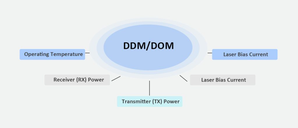
Optical modules must reliably report key parameters: temperature, supply voltage (Vcc), laser bias current, receiver (Rx) power, and transmitter (Tx) power. The MCU continually reads these analog metrics and interprets the module’s operating condition in real time.
This function aligns with SFF-8472 standards for digital diagnostics monitoring (DOM), enhancing module transparency and system safety.
b) Control of Laser and Safety Mechanisms
Within LINK-PP modules—whether using FP lasers or cooled EML lasers—the MCU adjusts laser output and enforces Class I safety standards. It modulates laser power and engages protective measures if parameters stray beyond safe thresholds.
For sensitive photodiodes, the MCU may also use current-sensing feedback loops to ensure stable operation, especially critical in high-speed modules.
c) Communication Interface via I²C
MCUs serve a dual I²C role: one interface communicates upward to the host system (e.g., switches or routers), while the other interfaces with internal analog front-end circuits. For example, the MAX32660 MCU provides I²C speeds up to 3.4 Mbps, meeting typical host communication needs.
3. Why MCUs Are Critical for LINK-PP Optical Transceivers
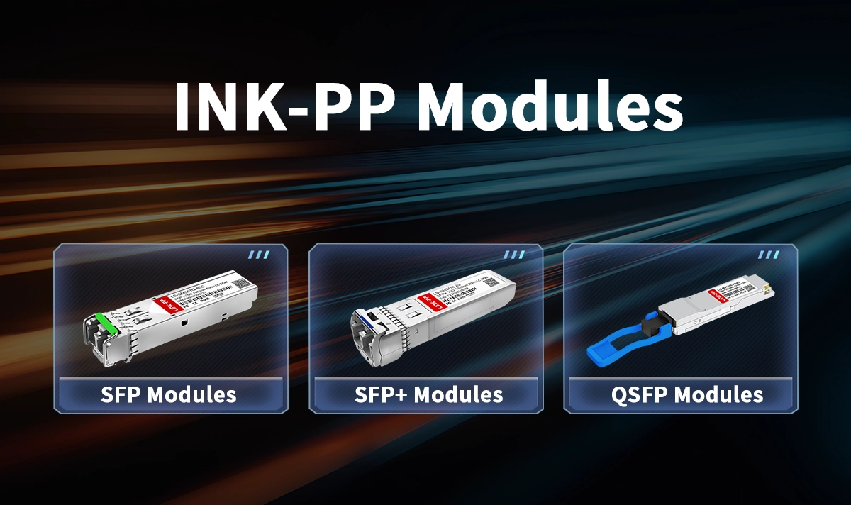
LINK-PP’s optical transceiver lineup—including SFP, SFP+, QSFP modules supporting diverse wavelengths (e.g., 1550nm) and data rates—relies on intelligent control to ensure reliability across hot-swappable deployments. The MCU’s real-time DOM capability supports proactive diagnostics and error detection, giving LINK-PP modules a strong edge in durability and trustworthiness.
4. Summary Table
Function | Description |
|---|---|
Diagnostics (DDM/DOM) | Real-time monitoring of temperature, Vcc, bias current, Rx/Tx power |
Laser & Safety Control | Precise control of laser output and protection under Class I standards |
I²C Communications | Internal interface to analog circuits and external communication with hosts |
Reliability in LINK-PP Modules | Enhances module performance, diagnostics, and operational trust |
5. Conclusion
Microcontroller Units are fundamental to modern optical transceiver modules. Through diagnostics, control, and communication, they uphold module health, safety, and reliability—especially in products like LINK-PP’s SFP and QSFP transceivers.
6. Also See
SFF-8472 Standard Explained | Digital Diagnostic Monitoring for Optical Transceivers – Details how DDM enables real-time parameter access via I²C.
DDM/DOM in Optical Transceivers – Glossary entry explaining DDM and DOM fundamentals.
What Is a 1550nm Optical Transceiver and How Does It Work? – Insights into module architecture including MCU usage and laser types.
EML Laser Diodes Explained for Optical Modules – Overview of EML technology suitable for high-speed, long-reach modules.
Understanding FP (Fabry-Pérot) Lasers in Optical Transceiver Modules – FP laser characteristics and applications in cost-effective modules.


