
In the relentless pursuit of faster data transmission, where terabits of information flow through fiber optic cables every second, maintaining signal integrity is paramount. One critical technology silently ensuring this reliability is CDR, or Clock and Data Recovery. This blog dives deep into what CDR is, why it's indispensable in modern optical communication, and how it empowers devices like optical transceivers to perform flawlessly.
✦ Understanding the Core Problem: Signal Degradation
Imagine sending a perfectly timed, crisp digital signal across kilometers of optical fiber. During its journey, this signal encounters numerous challenges:
Attenuation: The signal weakens over distance.
Dispersion: Different wavelengths (colors) of light travel at slightly different speeds, causing the signal pulse to spread and blur.
Noise: Electrical interference and optical amplification add unwanted disturbances (jitter).
Timing Variations (Jitter): The exact timing of the signal pulses can become unstable due to various physical factors.
The result? By the time the signal reaches its destination, it’s often distorted, noisy, and its precise timing (the "clock") is obscured. Simply amplifying it isn't enough; we need to accurately reconstruct the original digital data stream and its exact timing.
✦ Enter CDR: The Signal Rejuvenator
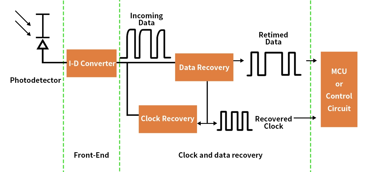
This is where the Clock and Data Recovery circuit comes in. Think of it as a highly sophisticated traffic controller and signal cleaner rolled into one. Its primary mission is two-fold:
Recover the Clock: Extract a stable, precise clock signal that matches the average timing (bit rate) of the incoming data stream, even amidst significant timing fluctuations (jitter).
Recover the Data: Use this recovered clock to sample the incoming distorted data waveform at the optimal instant within each bit period, making a clean decision whether a '1' or a '0' was sent, thereby regenerating a pristine digital output signal.
✦ How Does CDR Work? The Technical Heartbeat
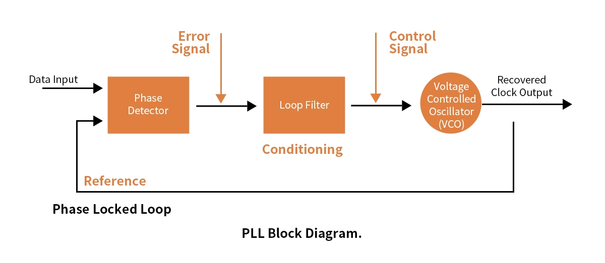
A typical CDR circuit employs a closed-loop feedback system, often centered around a Phase-Locked Loop (PLL) or a Delay-Locked Loop (DLL). Here's a simplified breakdown:
Phase Detector (PD): Compares the phase (timing relationship) between the incoming data transitions (edges) and the clock signal generated internally by the CDR's Voltage-Controlled Oscillator (VCO).
Charge Pump (CP) & Loop Filter (LF): The PD generates error signals. The CP converts these into current pulses, and the LF smoothes them into a stable control voltage. This filter is crucial for setting the CDR's bandwidth – its ability to track jitter.
Voltage-Controlled Oscillator (VCO): Generates the clock signal. The control voltage from the LF adjusts the VCO's frequency/phase to align perfectly with the incoming data's timing.
Data Sampler (Decision Circuit): Once the clock is locked, it triggers a sampler (like a flip-flop) to read the data signal at the precise moment when the signal level is most stable (typically the center of the bit period). This regenerates clean digital data.
✦ Key CDR Specifications to Understand
When evaluating optical modules or CDR performance, these specifications matter:
Jitter Tolerance: The maximum amount of input jitter the CDR can handle without increasing errors (measured in UI pp - Unit Interval peak-to-peak).
Jitter Transfer: How much jitter the CDR "passes through" from input to output (ideally low, especially at low frequencies).
Jitter Generation: The amount of new jitter the CDR circuit itself adds to the output signal (ideally very low).
Lock Range: The range of input data rates over which the CDR can acquire and maintain lock.
Lock Time: How quickly the CDR can achieve phase lock upon receiving a signal.
Bit Error Rate (BER): The ultimate measure – how many errors the CDR contributes to after regeneration (aiming for <10^-12 or better).
✦ Why is CDR Absolutely Critical for Optical Transceivers?
Optical transceivers are the workhorses converting electrical signals from network equipment (switches, routers) into optical signals for fiber transmission, and vice versa. As data rates skyrocket (100G, 200G, 400G, 800G and beyond), the challenges of signal degradation become exponentially harder. CDR is no longer optional; it's fundamental:
Mitigating Inter-Symbol Interference (ISI): At high speeds, dispersion and bandwidth limitations cause bits to smear into each other. CDR sampling at the optimal point minimizes errors caused by this smearing.
Jitter Tolerance and Filtering: CDRs absorb incoming jitter within their tracking bandwidth (called jitter tolerance) and filter out higher-frequency jitter (jitter transfer/jitter generation), outputting a cleaner signal.
Signal Regeneration: CDR cleans up noise and distortion, effectively "resetting" the signal quality before it travels further electrically within the host system.
Enabling Longer Reach: By cleaning the signal, CDR allows optical modules to achieve specifications for longer transmission distances (e.g., ER, LR, ZR).
Interoperability: CDRs help compensate for variations in signal quality coming from different equipment manufacturers, ensuring modules work reliably together.
CDR Approaches in Optical Modules
Different module types and applications utilize CDR differently:
CDR Approach | Description | Typical Use Case in Optical Transceivers | Pros | Cons |
|---|---|---|---|---|
Integrated CDR | CDR circuitry is embedded directly within the optical transceiver module, typically on the DSP chip. | Coherent modules (CFP2, QSFP-DD), High-speed PAM4 (200G+, 400G, 800G) | Highest performance, optimized integration, simplifies host design | Increases module cost and power consumption |
Host-Based CDR | CDR function is performed by a circuit on the host system's line card, before the signal reaches the module's electrical interface. | Some lower-speed or shorter-reach applications | Reduces module cost and complexity | Places burden on host design, limits module flexibility |
Module CDR | CDR circuitry is located on the transceiver module's board, often using a separate IC alongside the laser driver/TIA. | Common in many 10G, 25G, some 100G SR/LR modules | Good balance, isolates host from signal issues | Uses module PCB space, adds cost |
✦ The Role of Advanced DSP and CDR in Modern Transceivers
For complex modulation schemes like coherent optics (using DP-QPSK, 16QAM, etc.) or high-speed PAM4 (Pulse Amplitude Modulation 4-level) used in 200G, 400G, and 800G, CDR is tightly integrated with a powerful Digital Signal Processor (DSP). The DSP handles:
Complex CDR: Recovering clock and data from multi-level or phase-modulated signals.
Advanced Equalization: Compensating for massive dispersion (CD, PMD) and non-linear effects electronically (EDC, FEC).
FEC (Forward Error Correction): Adding and decoding redundant bits to correct errors introduced during transmission.
In these modules, the DSP is the brain, and CDR is a critical sensory input mechanism, working together to overcome extreme channel impairments. Finding a reliable optical transceiver supplier (like LINK-PP) offering modules with robust DSP and CDR capabilities is crucial for high-performance networks.
✦ LINK-PP: Delivering High-Performance Optical Solutions with Integrated CDR

At LINK-PP, we understand the critical role CDR plays in ensuring signal integrity for demanding network applications. Our portfolio of high-speed optical transceiver modules leverages advanced CDR technology, often integrated within powerful DSPs, to deliver exceptional performance and reliability:
High-Speed PAM4 Modules: Our LQD-CW400-DR4C module feature integrated DSPs with sophisticated CDR and equalization, enabling error-free transmission over multimode fiber.
Long-Haul Coherent Solutions: LINK-PP's 100G CFP2-DCO and 400G QSFP-DD coherent modules utilize state-of-the-art coherent DSPs with ultra-precise CDR, compensating for chromatic and polarization mode dispersion across hundreds of kilometers.
Cost-Effective Duplex Solutions: For enterprise and data center interconnect (DCI) applications, our 100G QSFP28 LR4 and 100G QSFP28 ER4 modules incorporate essential CDR functionality to ensure robust performance over single-mode fiber up to 40km. Upgrade your network infrastructure with LINK-PP transceivers designed for maximum signal integrity.
✦ The Future of CDR: Pushing Speed and Efficiency
As we march towards 1.6T and beyond, CDR technology continues to evolve:
Higher Speeds: CDR circuits operating at 224 Gbps per lane are already in development for next-generation modules.
Lower Power: Integrating CDR/DSP functionality more efficiently is paramount to manage the power budgets of dense systems.
Advanced Modulation: CDR techniques for even more complex modulation schemes.
CPO (Co-Packaged Optics) & NPO (Near-Packaged Optics): CDR functionality will be tightly integrated closer to the switch ASIC, requiring new architectures and lower power.
✦ Conclusion: CDR – The Unsung Hero of Reliable Data
Clock and Data Recovery is far more than just a technical component; it's a fundamental enabler of high-speed, long-distance optical communication. By meticulously extracting timing and cleaning distorted signals, CDR ensures the billions of bits traversing global networks arrive accurately and reliably. Whether embedded within a sophisticated coherent DSP or a dedicated IC in a standard module, CDR technology is vital for the performance of modern optical transceiver modules.
Understanding CDR empowers network engineers to make informed decisions about optical transceiver selection and appreciate the complex engineering that keeps our digital world connected. As speeds increase and reach demands grow, the role of robust CDR solutions, like those integrated into LINK-PP modules, becomes ever more critical.
Ready to ensure optimal signal integrity in your network? Explore LINK-PP's range of high-performance optical transceivers featuring advanced CDR technology. Contact LINK-PP today for expert advice on selecting the right modules for your high-speed connectivity needs!
✦ FAQ
Q1: What does Clock and Data Recovery do in a digital system?
Clock and Data Recovery finds the timing and data from a signal. It helps the receiver know when to read each bit. This keeps the data correct and in order.
Q2: What problems can happen without CDR?
Without CDR, the receiver may read data at the wrong time. This can cause errors, lost data, or broken communication. Systems may not work well at high speeds.
Q3: What devices use Clock and Data Recovery?
Many devices use CDR. Examples include computers, network switches, optical transceivers, and storage devices. These devices need fast and reliable data transfer.
Q4: What is jitter, and why does it matter for CDR?
Jitter means the timing of data edges moves around. Jitter can make it hard for CDR to find the right timing. Too much jitter can cause errors.
Q5: What makes a good CDR circuit?
A good CDR circuit keeps timing steady, handles noise, and works at high speeds. It uses strong phase detectors and filters. Engineers test CDR circuits to make sure they work in many conditions.
✦ See Also
The Importance Of Digital Diagnostics Monitoring In Optical Devices
Exploring Wavelength Division Multiplexing And Its Network Uses
Introducing The LINK-PP Network And Its Supportive Community


