


🧲Understanding the Turns Ratio in Ethernet Magnetics
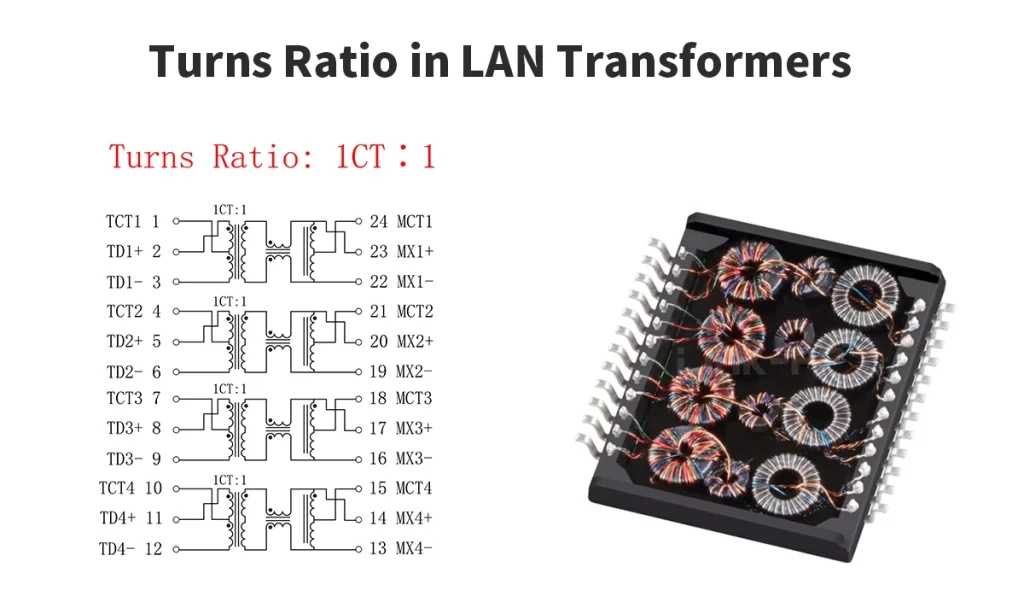
The turns ratio in LAN transformers—also known as Ethernet magnetics—is a critical design parameter that defines the relationship between the number of windings (turns) on the primary side (PHY side) and the secondary side (cable side) of the transformer. It is typically represented as a ratio such as 1:1 or 2.5:1, and it directly affects signal integrity, impedance matching, and Power over Ethernet (PoE) compatibility in Ethernet applications.
🧲Why Does the Turns Ratio Matter in LAN Transformers?
1. Impedance Matching
The primary purpose of the transformer in an Ethernet circuit is to provide impedance matching between the PHY (Physical Layer IC) and the twisted-pair cabling (usually 100 Ω differential impedance). A 1:1 turns ratio typically maintains this impedance balance, ensuring minimal signal reflection and maximum power transfer.
2. Voltage and Current Conversion
A non-1:1 turns ratio allows for adjustment of voltage and current levels. For example, a 2.5:1 turns ratio steps down the voltage by a factor of 2.5 while increasing the current proportionally, which is beneficial in PoE (Power over Ethernet) applications where different voltage levels must be supported across isolation barriers.
3. Signal Isolation and Protection
All Ethernet transformers, regardless of their turns ratio, provide galvanic isolation (commonly 1500 Vrms) between the PHY and the external Ethernet cable. This helps protect sensitive ICs from voltage surges, ground loops, and EMI.
🧲Common Turns Ratio Configurations
Application Type | Typical Turns Ratio | Notes |
|---|---|---|
10/100BASE-T Ethernet | 1:1 | Standard for legacy Ethernet |
1000BASE-T (Gigabit) | 1:1 or Center-tap | Optimized for full-duplex signaling |
PoE / PoE+ (802.3af/at) | 2.5:1 or higher | Supports higher voltage on cable side |
Multi-gig Ethernet (2.5G/5G/10G) | Depends on PHY | Requires careful matching & shielding |
📌 Example: LINK-PP’s LP5019NL 1G LAN transformer uses a 1CT:1 turns ratio for compatibility with IEEE 802.3u and 802.3ab standards.
🧲How to Select the Correct Turns Ratio?
Choosing the right turns ratio depends on multiple system-level factors:
PHY output swing voltage
Common-mode noise rejection
PoE voltage class (e.g., IEEE 802.3af, at, bt)
Compliance with IEEE 802.3 standards
Insertion loss and return loss targets
Always consult the PHY vendor’s transformer guidelines to ensure the selected turns ratio meets the required signal swing, current handling, and isolation specifications.
🧲Frequently Asked Questions (FAQ)
Q1: Is 1:1 always the best choice?
Not necessarily. While 1:1 is common and works well for signal integrity in many Ethernet PHYs, PoE designs often require other ratios like 2.5:1 to manage higher voltages.
Q2: Can I mix different turns ratios in the same system?
No. All transformers in the same Ethernet link must be electrically compatible. Mismatched ratios will lead to signal distortion, impedance mismatches, or power delivery failure.
Q3: Does the turns ratio affect data speed?
Indirectly. The turns ratio must support the voltage swing and frequency range required by the data rate. For example, a transformer designed for 1000BASE-T must handle up to 125 MHz signal bandwidth.
🧲Conclusion
The turns ratio is more than just a number—it’s a vital transformer specification that affects signal performance, power transfer, and standard compliance in LAN applications. A well-matched turns ratio ensures optimized communication between Ethernet PHYs and twisted-pair cables, particularly in designs involving Power over Ethernet (PoE) and Gigabit Ethernet.
Looking for high-performance LAN transformers? LINK-PP offers a full range of IEEE-compliant modules with optimized turns ratios for 10/100/1000BASE-T, PoE, and multi-gigabit applications.


