


PSE (Power Sourcing Equipment) supplies DC power over Ethernet cabling; PD (Powered Device) consumes it. PoE standards (IEEE 802.3af/at/bt) define how much power can be offered and how PSE and PD safely detect and negotiate power. Understanding PSE vs PD matters for correct device selection, system reliability, thermal and cable planning, and compliance.
1. Clear Definitions
Modern Ethernet networks don’t just carry data — they deliver power too.
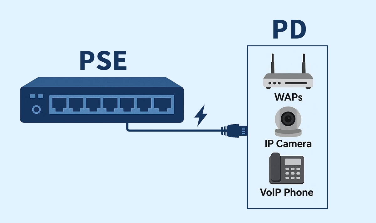
This capability, known as Power over Ethernet (PoE), enables devices such as wireless access points, IP cameras, and VoIP phones to receive both data and DC power through a single twisted-pair cable.
At the heart of every PoE system are two essential components:
PSE (Power Sourcing Equipment) — the device that supplies power.
PD (Powered Device) — the device that receives power.
Understanding how these two interact is key to designing efficient, reliable, and standards-compliant PoE networks.
PSE — Power Sourcing Equipment
A PSE is any device that injects power onto Ethernet twisted pairs: PoE-capable switches (endspan) or inline injectors/midspans. The PSE is responsible for detection, classification, and managing power allocation per port.
The PSE’s role is to detect whether a connected device is PoE-compatible, determine its power requirements, and safely supply the correct voltage and current. Detection and classification mechanisms ensure non-PoE devices are never accidentally powered, protecting sensitive equipment.
Common types of PSE:
Endspan PSE: Integrated directly into a PoE switch port.
Midspan PSE: External injector placed between a non-PoE switch and the PD.
PSE devices conform to IEEE standards that specify maximum output power per port and negotiation methods.
PD — Powered Device
A PD is any device that receives power from a PSE over the Ethernet cable, e.g., wireless access points (WAPs), IP cameras, VoIP phones, small switches, or IoT devices. PDs must present a defined signature so the PSE can detect and safely enable power.
Each PD contains a PoE interface with detection circuitry and DC-DC conversion, enabling it to operate safely and efficiently from the supplied voltage (typically 44–57 V DC).
2. How PSE and PD Work Together
A PoE connection begins with a handshake — a detection process to confirm whether the connected device supports PoE. The PSE sends a small voltage to identify the PD’s signature resistance.
If valid, the PSE proceeds with classification, determining how much power the PD needs (e.g., Class 0–8).
Once confirmed, the PSE applies full operating voltage and begins power delivery, while the PD’s internal converter stabilizes power for its circuitry.
Modern PoE+ and PoE++ systems may also use LLDP (Link Layer Discovery Protocol) to negotiate power dynamically, improving energy efficiency and network control.
3. PoE Standards and Power Levels
Standard | Type | PSE Max Power | PD Power Available | Typical Applications |
|---|---|---|---|---|
IEEE 802.3af | Type 1 | 15.4W | 12.95W | IP Phones, Basic WAPs |
IEEE 802.3at | Type 2 | 30W | 25.5W | PTZ Cameras, Dual-Band APs |
IEEE 802.3bt | Type 3 | 60W | 51W | Thin Clients, POS Terminals |
IEEE 802.3bt | Type 4 | 90–100W | 71–73W | Pan-Tilt-Zoom Cameras, LED Panels, Access Controllers |
Note: The difference between PSE and PD power is due to cable resistance losses.
These standards ensure compatibility across vendors and safeguard equipment from electrical faults.
4. Practical Considerations When Selecting PSE and PD
✔ Match the standard:
Ensure your PSE supports the PD’s power class. Using a PoE (802.3af) switch for a PoE+ camera will result in a power failure.
✔ Plan for power budget:
Switches share total power across all ports; always leave a margin for peak loads.
✔ Check cabling:
Higher power (PoE++) requires Cat6 or Cat6a cables to reduce heating and loss.
✔ Thermal and safety management:
High-power installations should follow IEEE cable-bundling and derating recommendations.
✔ Use compliant components:
Certified PoE RJ45 connectors and magnetics ensure isolation, EMI suppression, and safe current handling.


