


In the high-stakes world of data transmission, whether it’s a sprawling fiber optic network or a critical wireless bridge, clarity is king. But what happens when your signal weakens, data rates drop, and errors creep in? You’re likely facing the silent, invisible challenge of Link Budget Loss.
Simply put, your Link Budget is the accounting of all the gains and losses in a communication system. It’s the fundamental equation that determines if your signal has enough strength to travel from the transmitter to the receiver and be understood. When losses outweigh gains, your connection fails.
This post will demystify Link Budget Loss, explore its key contributors, and provide a actionable guide to ensuring your links are robust, reliable, and future-proof. We’ll also shine a light on a critical component where loss often hides: the optical transceiver.
📝 What Exactly is Link Budget? The Core Equation
Think of your signal as a traveler on a long journey. The Link Budget is its “energy fund.” It starts with the transmitter’s power (its initial cash) and must survive various “tolls” (losses) along the way to still have enough strength (power) to be received clearly.
The fundamental equation is:
Received Power (dBm) = Transmit Power (dBm) + Gains (dB) – Losses (dB)
For a link to be viable, the Received Power must be greater than the receiver’s sensitivity (the minimum power it needs to decode the signal). Link Budget Loss is the sum of all the “Losses” in this equation. Exceeding your budget means a complete communication breakdown.
📝 The Usual Suspects: Key Contributors to Link Budget Loss
Link Budget Loss isn’t a single monster but a swarm of smaller ones. Understanding each is the first step to mitigation.
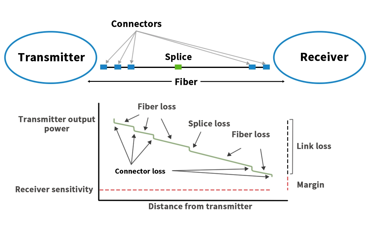
Path Loss (Attenuation): The inevitable weakening of a signal as it travels through a medium like fiber optic cable or free space. In fiber, this is primarily due to scattering and absorption.
Connector Loss: Every connection point—patch panels, jumper cables—introduces a small but significant loss due to imperfections and misalignment.
Splice Loss: Permanent joins between two fiber strands are not perfect, leading to signal attenuation.
Bend Loss: Sharp bends in fiber optic cables can cause light to leak out, a particular concern in dense data center environments.
Component Insertion Loss: This is a major, yet often overlooked, factor. Every passive and active component in the path, especially the optical modules itself, has an inherent insertion loss. Using high-quality, low-loss transceivers is non-negotiable.
📝 The Transceiver’s Tale: Your First Line of Defense Against Loss
The optical transceiver is the heart of your fiber link, converting electrical signals to light and back again. Its quality directly and dramatically impacts your Link Budget. A cheap, low-quality transceiver can have a higher intrinsic insertion loss and poorer performance, eating into your budget before the signal even hits the fiber.
When selecting high-performance optical transceivers, you must scrutinize their specifications. For instance, when planning a network upgrade, choosing the right 400G QSFP-DD optical transceiver is crucial for maintaining a healthy power margin. This is where the engineering excellence of a brand like LINK-PP becomes critical. LINK-PP transceivers are designed with superior components and precise calibration to ensure minimal insertion loss and maximum output power, giving your link budget a head start.
For example, the LINK-PP 400G-ZR+ coherent pluggable module is engineered for long-haul DCI and metro applications, featuring exceptionally low transmit power and high receiver sensitivity, effectively expanding the usable link budget for demanding 400G deployments.
📝 Calculating Your Own Link Budget: A Practical Table
To make this tangible, let’s look at a simplified example for a hypothetical 10km fiber link.
Factor | Value | Note |
|---|---|---|
Transmit Power | 0dBm | Output of the LINK-PP transceiver |
Fiber Attenuation | -3.5dB | 10km @ 0.35dB/km (standard for SMF) |
Connector Loss | -1.0dB | 2 connectors @ 0.5dB each |
Splice Loss | -0.2dB | 2 splices @ 0.1dB each |
Transceiver Insertion Loss | -1.0dB | Loss through the device itself |
Total Losses | -5.7dB | Sum of all losses above |
Received Power | -5.7dBm | 0dBm (Tx) – 5.7 dB (Loss) |
Receiver Sensitivity | -14.0dBm | Minimum power the receiver needs |
Power Margin | +8.3dB | Received Power – Sensitivity |
✅ Result: A healthy +8.3dB Power Margin! This link is stable and has room for degradation over time.
📝 Best Practices to Minimize Loss and Future-Proof Your Network
Start with Quality Components: Never compromise on optical transceivers and cabling. Invest in reputable brands like LINK-PP.
Minimize Connectors and Splices: Plan your paths to reduce the number of connection points.
Respect the Bend Radius: Avoid tight bends in fiber cables. Use proper cable management.
Calculate and Validate: Always perform a theoretical link budget calculation during design and validate it with real-world power meter testing after installation.
Plan for Margin: Always include a safety margin (3-5dB is common) to account for component aging and unexpected losses.
📝 Conclusion: Don’t Let Losses Silence Your Signal
Link Budget Loss is a fundamental concept that cannot be ignored. By understanding its components, meticulously calculating your budget, and investing in high-quality infrastructure—especially precision-engineered optical transceivers from leaders like LINK-PP—you can build networks that are not only functional but also resilient and ready for the demands of tomorrow.
Ready to Optimize Your Network’s Performance?
Don’t leave your signal strength to chance. If you’re designing a new link or troubleshooting an unstable one, a deep dive into your Link Budget is the answer.
📞 [Contact our experts today] to ensure your network operates at its peak potential with LINK-PP’s reliable optical solutions!
📝 FAQ
What is link budget loss?
Link budget loss shows you how much signal power drops as it moves from the transmitter to the receiver. You use this value to check if your network can send data without problems.
What causes link budget loss in fiber optic systems?
You see link budget loss from fiber length, connectors, splices, and cable bends. Each part adds a small amount of loss. You must count every part to get the total loss.
What is a good link loss margin?
You should keep your link loss margin above 3dB. This extra margin helps your network stay strong when conditions change or small problems happen.
What happens if you ignore link budget loss?
You risk weak signals and dropped connections. Your network may not work as planned. You need to check link budget loss to keep your system reliable.


