
Forward Error Correction (FEC) is a foundational technology in modern optical communication systems, particularly crucial for high-speed data transmission across long distances. It enhances data integrity by enabling the receiver to detect and correct bit errors without the need for retransmission. This capability improves reliability, efficiency, and performance in optical networks.
In this article, we’ll explore what FEC is, how it works, the types of codes used, its role in optical transceivers, common Ethernet standards, and practical deployment considerations.
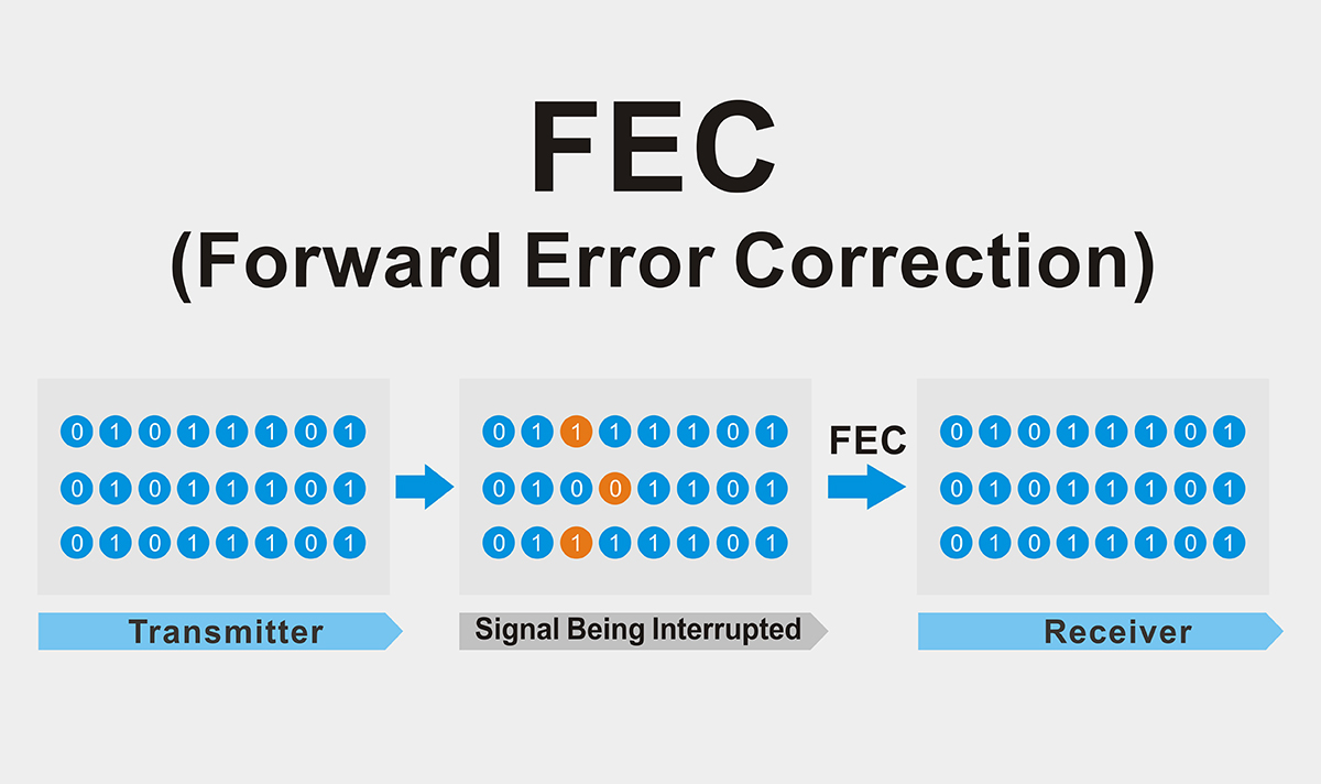
📘 What Is Forward Error Correction (FEC)?
Forward Error Correction (FEC) is a digital signal processing technique that adds redundant bits to a data stream, allowing the receiver to identify and correct transmission errors proactively.
In high-speed optical networks (e.g., 25G, 100G, 200G, 400G), FEC is essential for:
Reducing Bit Error Rate (BER)
Supporting longer transmission distances
Ensuring signal integrity in noisy or lossy conditions
Maintaining interoperability across multivendor environments
⚙️ How Does FEC Work?
FEC encodes outgoing data with additional bits based on well-defined mathematical rules. The receiver uses these bits to detect and correct a limited number of errors caused by impairments like dispersion, noise, or crosstalk.
Common FEC Code Types:
Reed-Solomon (RS) Codes
Block-based codes widely used in Ethernet and optical transceivers. RS(528,514) and RS(544,514) configurations can correct multiple symbol errors and are suited for burst-error correction.BCH (Bose–Chaudhuri–Hocquenghem) Codes
Binary codes offering high error correction with low latency, sometimes used in hardware-constrained systems. Their use in modern PAM4 systems is limited.LDPC (Low-Density Parity-Check) Codes
Known for near-Shannon-limit performance, LDPC is adopted in 400G/800G Ethernet and coherent systems. It provides superior correction for high symbol error rates but requires more complex decoders and introduces more latency.
🔍 Examples:
In 100G Ethernet systems like 100GBASE-LR4, RS-FEC (typically RS(528,514)) is employed to compensate for optical impairments over long-reach fiber links. It ensures that the system can meet a post-FEC BER target of 10⁻¹² or better, even when the raw pre-FEC BER may be in the 10⁻³ range.
🧩 Why FEC Matters in Optical Transceivers
FEC is critical in optical modules, especially at speeds of 25Gbps and above. It enables:
✅ Reliable operation over longer fiber runs
✅ Compatibility with lower-grade optical components
✅ Seamless interoperability between equipment from different vendors
✅ Meeting stringent BER targets, particularly in PAM4 modulated systems
FEC allows the use of cost-effective optical components by compensating for physical limitations with digital correction. However, FEC latency and the type of FEC used must align with system requirements and supported standards.
📏 Common FEC Standards in Ethernet
Standard | FEC Type | Application |
|---|---|---|
IEEE 802.3bj | RS(528,514) | 100GBASE-CR4, 100GBASE-KR4 (NRZ) |
IEEE 802.3by | RS(528,514) | 25GBASE-CR-S (NRZ) |
IEEE 802.3cd | KP4-FEC (RS(544,514)) | 50G, 100G, 200G (PAM4) |
100G Lambda MSA | RS(544,514) | PAM4 100G single-lane optics |
🔎 Note: RS(544,514), also known as KP4-FEC, is a stronger variant required for PAM4-based systems due to their inherently higher symbol error rates. Disabling FEC on such links is generally not permitted by standards.
⚠️ Key Considerations for FEC Deployment
FEC must be enabled at both ends of the optical link. Mismatched configurations (e.g., one end FEC-enabled, the other not) can prevent link establishment or result in high BER.
PAM4 systems, such as 100G DR, 200G FR4, or 400G DR4, require FEC to meet minimum BER targets due to the denser modulation format.
FEC adds latency (e.g., ~100ns–200ns for KP4-FEC), which may be significant in latency-sensitive applications.
Post-FEC BER vs. Pre-FEC BER: Most system specs refer to post-FEC BER. Understanding this distinction is vital when evaluating system performance.
🔌 FEC Support in LINK-PP Optical Modules
At LINK-PP, many of our transceivers are designed for full FEC compatibility across IEEE and MSA standards:
Product Example | Supported FEC | Use Case |
|---|---|---|
RS(528,514) | Short-reach data center links | |
RS(528,514) / optional KP4 | 2 km PAM4 | |
KP4-FEC (RS(544,514)) | 500m to 2km PAM4 links |
All modules are tested for interoperability, FEC tolerance, and compliance with physical and electrical interface specs.
❓ Frequently Asked Questions
Q1: Is FEC handled by the transceiver or the host?
A: FEC is typically implemented in the host device (e.g., switch MAC/PHY). Most optical modules do not contain FEC logic but are designed to be compatible with FEC-enabled signals.
Q2: Can I disable FEC in my network?
A: It depends. On NRZ links (e.g., 10G SFP+), FEC may be optional. But on PAM4-based systems, FEC is required by standard and disabling it may render the link unusable.
✅ Conclusion
FEC is no longer optional—it’s essential for maintaining the integrity of high-speed optical communications, especially as we scale toward PAM4 and terabit-class interconnects.
Whether you're deploying 25G Ethernet or scaling toward 800G, understanding how FEC works—and selecting modules that fully support the required FEC standards—ensures long-term network stability, compatibility, and performance.
🔧 Deployment Tip: Always ensure FEC settings are consistently enabled or disabled at both ends of the link to avoid mismatch errors. Consult your transceiver datasheets and switch configuration guides when in doubt.
See Also
Understanding The Role Of EDFA In Optical Networks
The Process Behind Data Transmission Using Optical Transceivers
Exploring FWDM Filters And Their Impact On Optical Networks
Comparing Optical Transceivers And Fiber Media Converters
Popular Fiber Connector Varieties Used In Optical Transceivers


