


Introduction
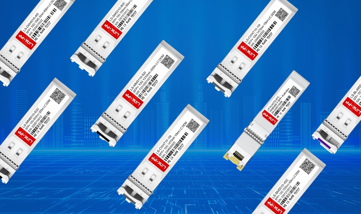
10G SFP+ optical modules remain one of the most widely deployed transceiver solutions in data centers, telecom networks, enterprise switching, and cloud-scale architectures. Their compact size, low power consumption, and versatility across multimode and single-mode fiber make them a critical component of modern high-speed connectivity.
However, the long-term stability and optical performance of any SFP+ module depend heavily on proper installation, handling, and environmental controls. This guide consolidates best practices referenced from established engineering sources, including IEEE 802.3 standards, optical safety norms (IEC 60825-1), and industry maintenance guidelines, to help engineers deploy SFP+ modules safely and reliably.
1. ESD Protection: Preventing Electrostatic Damage
Electrostatic discharge is one of the most common causes of premature transceiver failure. Technicians should always:
Wear an anti-static wrist strap and ensure proper grounding.
Avoid touching the PCB or exposed metal circuitry.
Handle the module using the body and latch, not the connector end.
Following standard ESD precautions significantly reduces latent defects that compromise long-term reliability.
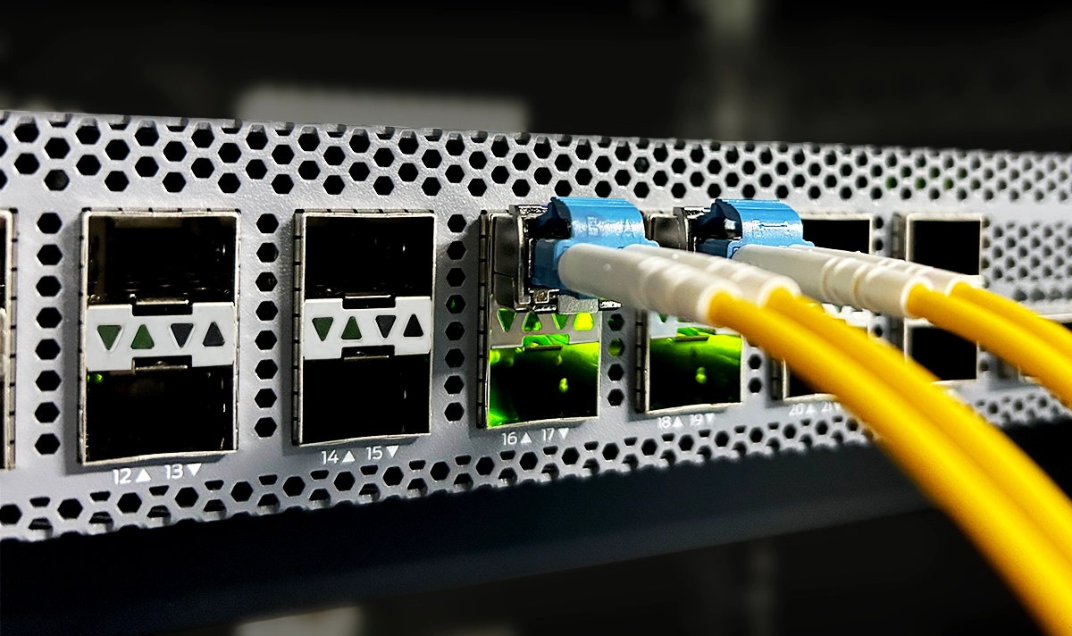
2. Optical Connector Cleaning and Contamination Control
Even microscopic dust on an LC/UPC connector can increase insertion loss and introduce link instability. Before mating connectors:
Clean the LC end face with a lint-free optical cleaning cloth or reel-type cleaner.
Inspect both the fiber jumper and the transceiver port.
Avoid mixing clean and contaminated connectors; contamination transfers instantly.
Maintaining clean optics is essential for achieving stable optical budgets, especially for LR, ER, and ZR modules with tight power margins.
3. Minimize Unnecessary Hot-Swapping
SFP+ modules support hot-plugging per IEEE 802.3ba, but frequent insertion and removal can:
Wear down the cage connector
Affect the mechanical integrity of LC latch components
Increase the risk of port damage
For best results, avoid unnecessary re-seating and ensure that modules are inserted cleanly without excessive force.
4. Verify Host Voltage and Power Compliance
A 10G SFP+ module requires a host supply voltage of 3.135–3.465 V, as defined by the SFF-8431 and MSA specifications.
Voltage instability may lead to:
Module resets
TX power fluctuations
Long-term chip degradation
Always ensure the host equipment meets the required power parameters before installation.
5. Laser Safety: IEC Class 1 Precautions
10G modules use Class 1 lasers that are safe under normal operation, but technicians should never:
Look directly into the optical port
Use improvised tools to test laser output
Connect optical fibers while active without proper alignment
Follow IEC 60825-1 laser safety guidelines at all times.
6. Temperature and Environmental Requirements
Each module is rated for a specific operating case temperature (e.g., 0–70°C commercial, –40–85°C industrial).
To ensure thermal stability:
Install modules in well-ventilated equipment bays
Avoid long-term operation near the upper thermal limit
Prevent exposure to condensation, humidity, or corrosive environments
Temperature drift can cause wavelength shift or TX power fluctuations in high-power modules.
7. Fiber Bend Radius and Physical Handling
Improper fiber handling is a silent contributor to increased insertion loss. Adhere to:
A minimum bend radius of ≥ 30 mm (varies by cable type)
Zero pulling tension on the fiber when inserting the LC connectors
No tight bundling, pinching, or sharp cable routing
Maintaining proper fiber geometry preserves link quality.
8. Compatibility and Coding Verification
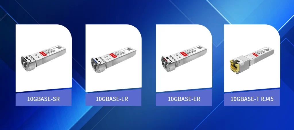
Before installation, verify:
Correct interface type: 10GBASE-SR, LR, LRM, ER, ZR
Supported wavelength (850 nm, 1310 nm, 1550 nm, CWDM, DWDM)
Vendor compatibility coding for Cisco, HPE, Juniper, Arista, etc.
Using mismatched or incorrectly coded modules can lead to error logs, link flaps, or power negotiation failures.
9. DOM Monitoring and Link Budget Validation
Digital Optical Monitoring (DOM) provides real-time data for:
Temperature
Supply voltage
TX/RX optical power
Laser bias current
Engineers should regularly review these parameters to ensure the link budget remains within the module’s specified operating range.
Sudden drops in TX/RX power may indicate contamination, excessive fiber loss, or equipment defects.
10. Dust Cap Handling and Port Protection
To prevent contamination:
Keep dust caps on until the moment of insertion
Replace the caps immediately if the module is removed
Avoid placing caps on dusty surfaces, where contamination can transfer to the connector
A clean connector environment directly correlates with optical performance.
11. Disable Ports Before Removal (When Recommended)
Some network operating systems (NOS) recommend disabling a port (“shutdown”) before removing a transceiver to reduce:
Log bursts
Unexpected alarms
Traffic re-routing anomalies
While not always mandatory, this is good practice for large-scale environments.
12. Pre-Warm and Stabilization for High-Power Modules
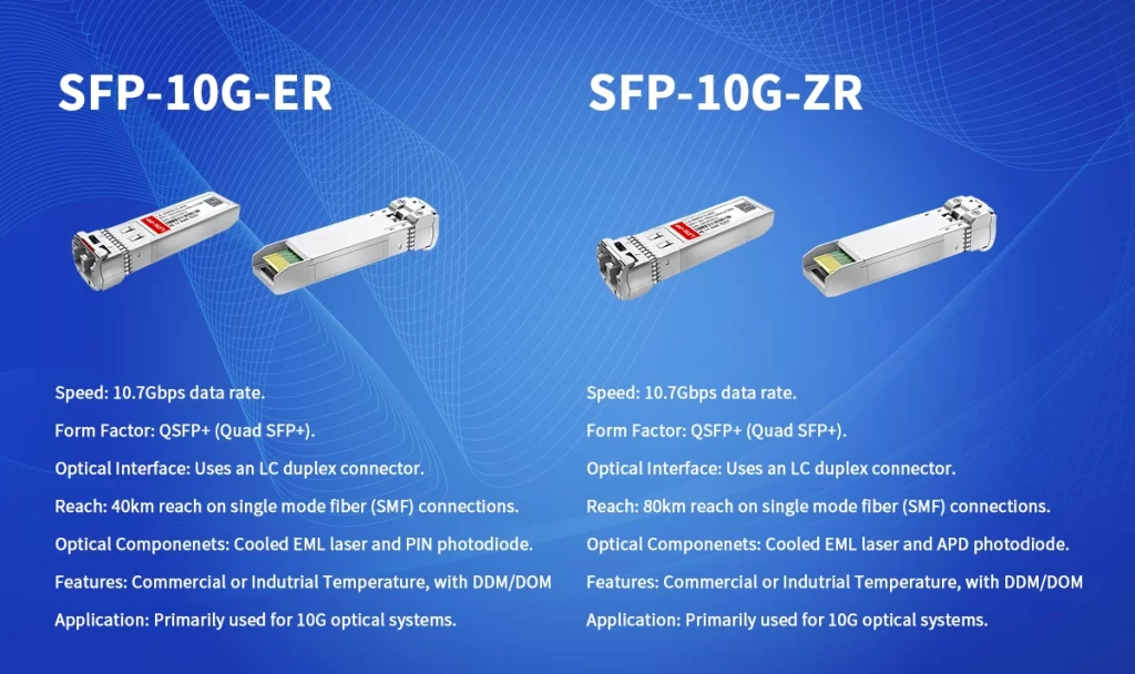
10G ER and ZR modules may require a short stabilization period during startup.
During this warm-up, the wavelength and power may vary slightly before reaching stable operation.
13. Use Only Verified Optical Attenuators
For short-reach deployments using high-power modules:
Choose attenuators matched to the correct wavelength and connector type
Avoid low-quality or unverified attenuators that cause back-reflection
This is crucial when RX power exceeds the receiver sensitivity threshold.
14. Scheduled Maintenance for Critical Links
For long-haul, data-center fabric, or aggregation-layer links:
Perform link inspections every 3–6 months
Clean connectors periodically
Check DOM logs for abnormal drift
Routine maintenance helps catch optical degradation early.
Conclusion
Carefully handling 10G SFP+ modules is essential to ensuring optimal optical performance, long-term stability, and safe operating conditions in modern high-speed networks. By following industry-aligned best practices—from connector cleaning and ESD protection to compatibility checks and DOM monitoring—engineers can significantly extend the service life of their transceivers and prevent unnecessary downtime.


