

In modern fiber-optic networks, SFP modules (Small Form-factor Pluggable transceivers) are widely used to connect switches, routers, and servers to fiber or copper cabling. These compact, hot-pluggable optical transceivers allow network engineers to flexibly select different transmission media, wavelengths, and distances without replacing the entire network interface hardware.
Because SFP modules act as the physical interface between networking equipment and transmission media, verifying that a module is installed correctly and operating within its optical parameters is essential for maintaining stable network connectivity. A misconfigured or faulty SFP can cause common issues such as link failures, low optical power, high error rates, or incompatibility with the host switch.
For this reason, network administrators frequently need to check SFP modules using switch diagnostics, command-line tools, and optical monitoring data. Many enterprise switches from vendors like Cisco and Juniper Networks provide built-in commands that allow engineers to read Digital Optical Monitoring (DOM or DDM) information such as temperature, voltage, transmit power, and receive power. These diagnostic values help determine whether a transceiver is functioning properly or approaching alarm thresholds.
In practice, checking an SFP module usually involves several steps:
Identifying the installed transceiver model
Verifying link status and interface information
Reading DOM/DDM optical diagnostics
Confirming switch compatibility and supported optics
Testing the module with known-good fiber connections
Understanding how to properly check and test SFP modules is therefore an essential skill for network engineers, data center operators, and IT administrators responsible for maintaining high-speed fiber links.
What You Will Learn in This Guide
In this article, you will learn:
How to check an SFP module on network switches (including Cisco CLI commands)
How to test an SFP transceiver using diagnostics and optical measurements
How to read SFP DOM/DDM parameters such as TX/RX optical power
How to identify which SFP module type is required for a specific network link
Common troubleshooting methods when an SFP module is not detected or fails
By the end of this guide, you will understand how to quickly verify, diagnose, and select the correct SFP module for reliable fiber-optic network operation.
➡️ What Is an SFP Module and Why Checking It Matters
An SFP module (Small Form-factor Pluggable transceiver) is a compact, hot-swappable interface used in switches, routers, and servers to connect network equipment to fiber optic or copper cabling. The SFP standard allows network engineers to easily deploy different transmission types—such as multimode fiber, single-mode fiber, or copper Ethernet—without changing the main network hardware.
SFP modules are widely used in Gigabit Ethernet, 10-Gigabit Ethernet, Fibre Channel, and other high-speed network protocols. Because they are removable and standardized under the Multi-Source Agreement (MSA), SFP transceivers from different vendors can often work with compatible networking equipment.
However, since the SFP module acts as the physical layer interface between the switch port and the network cable, any issue with the module can immediately impact link stability and performance. This is why network engineers frequently need to check SFP module status, monitor optical parameters, and verify compatibility when troubleshooting network problems.
Why Engineers Check SFP Module Status
Checking an SFP module is a routine task in network operations. Engineers typically perform SFP diagnostics to confirm that the transceiver is functioning properly and that the optical link meets expected performance levels.
Common reasons to check an SFP module include:
Verifying that the switch correctly detects the SFP transceiver
Checking link status and interface activity
Reading Digital Optical Monitoring (DOM/DDM) values such as transmit and receive optical power
Confirming module compatibility with the network switch
Identifying abnormal temperature or voltage conditions
Most enterprise network switches provide built-in commands that allow administrators to perform SFP diagnostics directly from the CLI, making it easier to detect hardware or optical issues without specialized external tools.
Common Network Failures Related to SFP Modules
Many fiber network issues are directly related to the transceiver or its connection to the fiber infrastructure. When troubleshooting network outages or unstable links, engineers often start by checking the SFP module.
Some of the most common SFP-related failures include:
Issue | Description |
|---|---|
Unsupported module | The switch firmware may reject non-approved or incompatible SFP modules |
Low RX optical power | Weak received signal due to long distance, dirty connectors, or damaged fiber |
Fiber mismatch | Using multimode fiber with a single-mode SFP or vice versa |
Dirty connectors | Dust or contamination on fiber connectors causing signal loss |
Hardware failure | Aging or defective SFP modules causing intermittent link drops |
By performing a quick SFP module check, engineers can quickly determine whether the issue originates from the transceiver, fiber cable, or network configuration, significantly reducing troubleshooting time in data center and enterprise networks.
Understanding how SFP modules work and how to properly check SFP diagnostics and link status is therefore an essential step in maintaining stable and reliable fiber network connectivity.
➡️ How to Check SFP Module in Cisco Switch
One of the most common questions in network operations is “How to check SFP Module in Cisco switch?” Cisco devices provide several built-in CLI commands that allow administrators to verify whether an SFP module is installed, detect its model, and read diagnostic information.
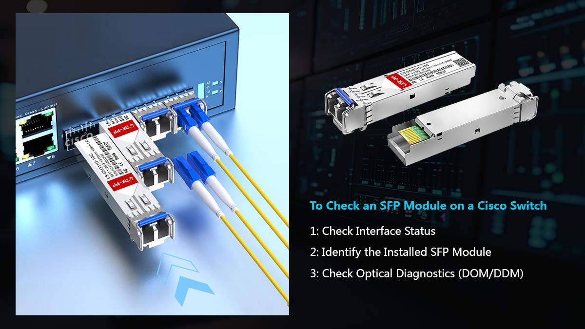
Checking an SFP module on Cisco switches typically involves viewing interface status, identifying the installed transceiver, and reading optical diagnostics (DOM/DDM data). These commands help engineers quickly determine whether a link issue is related to the SFP module, the fiber cable, or the switch port.
Below are the most commonly used Cisco CLI commands for checking SFP modules.
Command | Purpose |
|---|---|
| Displays port status, link state, speed, and whether an SFP module is detected |
| Lists all hardware components, including installed SFP transceivers and their model numbers |
| Shows basic SFP information such as presence and type |
| Displays detailed optical diagnostics including temperature, voltage, TX power, and RX power |
Step 1: Check Interface Status
The first step when verifying an SFP module is to check whether the interface is up and recognized by the switch.
show interface statusThis command displays key interface information such as:
Port state (connected / notconnect)
Speed (1G / 10G)
Duplex mode
Module detection
If the port shows “notconnect”, the issue may be related to the fiber cable, remote device, or the SFP module itself.
Step 2: Identify the Installed SFP Module
To confirm which SFP transceiver is installed, engineers commonly use:
show inventoryThis command lists the hardware model, vendor information, and serial number of installed transceivers. It helps verify whether the correct SFP module is being used.
Step 3: Check Optical Diagnostics (DOM/DDM)
For deeper SFP diagnostics, Cisco switches support commands that display real-time optical monitoring data.
show interfaces transceiveror
show interfaces transceiver detailThese commands provide important parameters such as:
Module temperature
Supply voltage
Laser bias current
Transmit optical power (TX)
Receive optical power (RX)
By analyzing these values, engineers can determine whether the SFP module is operating within normal ranges or experiencing optical signal issues.
Why These Commands Are Important for SFP Troubleshooting
Using these Cisco commands allows administrators to quickly check SFP module status and diagnose connectivity problems. For example:
If the SFP is not detected, the module may be incompatible or faulty.
If RX power is too low, the fiber cable may be damaged or too long.
If temperature values are abnormal, the transceiver may be overheating.
Regularly checking SFP status through CLI diagnostics is therefore a critical step in SFP troubleshooting and maintaining stable fiber network connections.
➡️ How to Test an SFP Module (Step-by-Step)
Testing an SFP module is an essential part of network troubleshooting and optical link verification. When a fiber link fails or experiences instability, engineers typically perform a structured test process to determine whether the issue is caused by the SFP transceiver, the fiber cable, or the switch port.
Below is a practical step-by-step method to test an SFP module, commonly used in enterprise networks and data centers.
Step 1. Perform a Physical Inspection
The first step when testing an SFP module is to inspect the hardware and fiber connections.
Check the following:
Ensure the SFP module is fully inserted into the switch port
Confirm the LC connectors are properly connected
Inspect the fiber patch cable for damage or bending
Clean the fiber connectors to remove dust or contamination
Dirty fiber connectors are one of the most common causes of optical signal loss and unstable links.
Step 2. Check Link Status on the Switch
Next, verify whether the switch detects the SFP module and whether the interface is active.
On most switches, engineers check:
Interface status
Link speed
Port state (up/down)
If the interface shows no link, the problem may be related to:
incompatible SFP module
disconnected fiber cable
incorrect fiber type
faulty switch port
Checking link status helps confirm whether the SFP module is communicating with the remote device.
Step 3. Read Optical Diagnostics (DDM / DOM)
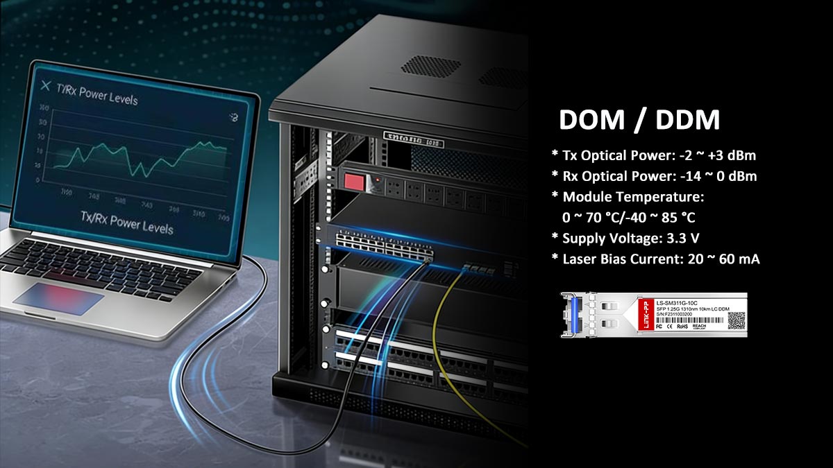
Most modern SFP transceivers support Digital Optical Monitoring (DOM) or Digital Diagnostics Monitoring (DDM), which provides real-time performance data.
Typical parameters include:
Parameter | What It Indicates |
|---|---|
Temperature | Internal module temperature |
Voltage | Electrical power supplied to the module |
TX Optical Power | Strength of the transmitted optical signal |
RX Optical Power | Strength of the received optical signal |
Laser Bias Current | Laser operating current |
If RX optical power is too low, the fiber link may be experiencing attenuation or connection issues. If the temperature or voltage is abnormal, the SFP module may be approaching hardware failure.
Step 4. Verify Fiber Type and Compatibility
Another critical step when testing an SFP module is confirming that the fiber type matches the transceiver specification.
Common mismatches include:
SFP Type | Required Fiber |
|---|---|
Multimode fiber (OM3 / OM4) | |
Single-mode fiber | |
Single fiber with wavelength pair |
Using the wrong fiber type can prevent the link from establishing even if the SFP module itself is functioning normally.
Step 5. Replace or Swap the SFP Module
If the previous checks do not resolve the issue, the final step is to swap the SFP module with a known-working transceiver.
This test helps isolate the problem:
If the link works with another SFP, the original module is likely defective.
If the problem persists, the issue may be related to the fiber cable or switch port.
Because SFP modules are hot-swappable, engineers can safely replace them without powering down the switch, which makes troubleshooting faster in production networks.
Following this systematic SFP testing process allows network engineers to quickly identify whether a problem originates from the transceiver, fiber infrastructure, or network equipment, reducing downtime and improving troubleshooting efficiency.
➡️ How to Read SFP Diagnostics (DOM / DDM Data)
Most modern SFP and SFP+ transceivers support Digital Optical Monitoring (DOM) or Digital Diagnostics Monitoring (DDM). These features allow network engineers to monitor the real-time operating status of an optical module, including electrical conditions and optical signal strength.
Reading these diagnostic values is one of the most effective ways to check SFP module health and identify potential network issues before a link fails.
Below are the most important SFP diagnostic parameters typically reported by switches and network equipment.
Parameter | Meaning |
|---|---|
Temperature | Internal temperature of the SFP module, used to monitor overheating |
Voltage | Electrical supply voltage provided to the transceiver |
TX Power | Optical power transmitted from the module to the fiber |
RX Power | Optical power received from the remote device |
Laser Bias Current | Current driving the laser diode inside the transceiver |
Understanding Each Diagnostic Parameter
Temperature
The module temperature indicates whether the transceiver is operating within its safe thermal range. Excessive heat may indicate poor airflow inside the switch or a failing module.
Typical operating range:
0°C to 70°C for commercial modules
-40°C to 85°C for industrial modules
Voltage
The supply voltage reflects the electrical stability of the module. Abnormal voltage values can suggest power regulation issues on the switch port or hardware degradation inside the transceiver.
TX Optical Power
TX power represents the strength of the optical signal being transmitted by the SFP module.
If TX power is significantly lower than expected:
the laser may be degrading
the module may be faulty
the SFP may not be compatible with the switch
RX Optical Power
RX power measures the incoming optical signal from the remote device. This value is extremely important for fiber link troubleshooting.
Low RX power can be caused by:
excessive fiber distance
dirty connectors
damaged fiber cables
incorrect fiber type (SMF vs. MMF)
Laser Bias Current
Laser bias current represents the electrical current driving the optical transmitter. When a laser begins to age, the module often increases the bias current to maintain optical output power.
A high bias current combined with low TX power is often a strong indicator that the SFP module is approaching hardware failure.
How to Identify a Faulty SFP Module
By analyzing DOM/DDM values, engineers can quickly determine whether an SFP module is functioning normally.
Typical warning signs include:
Symptom | Possible Cause |
|---|---|
RX power extremely low | Dirty connectors or fiber damage |
TX power outside normal range | Laser degradation |
Temperature too high | Cooling issue or failing module |
Bias current unusually high | Aging or failing laser |
No DOM data available | Non-DOM SFP or compatibility limitation |
When these abnormal readings appear, engineers typically clean fiber connectors, verify fiber type, or replace the SFP module to restore stable network operation.
Understanding how to interpret SFP diagnostics and DOM data is therefore essential for efficient SFP troubleshooting and fiber network maintenance.
➡️ How to Know What SFP Module to Use
A common question among network engineers is “How do I know what SFP module to use?” Choosing the correct transceiver is essential for ensuring stable connectivity, optimal performance, and compatibility with network equipment.
Selecting the right SFP module typically depends on several key technical factors, including network speed, fiber type, transmission distance, operating wavelength, and connector type. Understanding these parameters helps ensure that the SFP module matches both the network infrastructure and the application requirements.
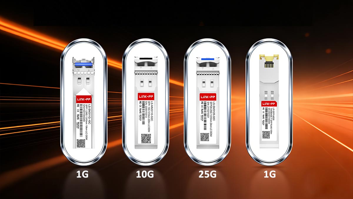
★ Network Speed (1G / 10G / 25G)
The first factor to consider is the data rate supported by the switch or router port.
Common SFP speed categories include:
Speed | Module Type | Typical Standard |
|---|---|---|
1 Gbps | SFP | 1000BASE-SX / LX |
10 Gbps | SFP+ | 10GBASE-SR / LR |
25 Gbps | 25GBASE-SR / LR |
Using the wrong speed class may prevent the module from working or cause the port to remain down or unsupported.
★ Fiber Type (MMF vs. SMF)
Another critical factor is whether the network uses multimode fiber (MMF) or single-mode fiber (SMF).
Fiber Type | Typical Modules | Use Case |
|---|---|---|
Multimode Fiber (MMF) | SX, SR | Short-distance data center links |
Single-Mode Fiber (SMF) | LX, LR, ER | Long-distance connections |
For example:
10GBASE-SR SFP+ → designed for multimode fiber
10GBASE-LR SFP+ → designed for single-mode fiber
Using the wrong fiber type can prevent the optical link from establishing.
★ Transmission Distance
The required link distance is another important consideration when selecting an SFP module.
Different optical standards support different maximum transmission distances:
Module Type | Typical Distance |
|---|---|
SR (Short Reach) | 300–400 m |
LR (Long Reach) | 10 km |
ER (Extended Reach) | 40 km |
If the fiber link exceeds the supported distance, the optical signal may become too weak for reliable communication.
★ Wavelength
Each optical transceiver operates at a specific laser wavelength, which determines how the optical signal travels through the fiber.
Common wavelengths include:
850 nm — typically used for multimode optics (SR)
1310 nm — commonly used for medium-distance single-mode optics (LR)
1550 nm — used for long-distance optics (ER / ZR)
Matching the wavelength between both ends of the link is essential for proper communication.
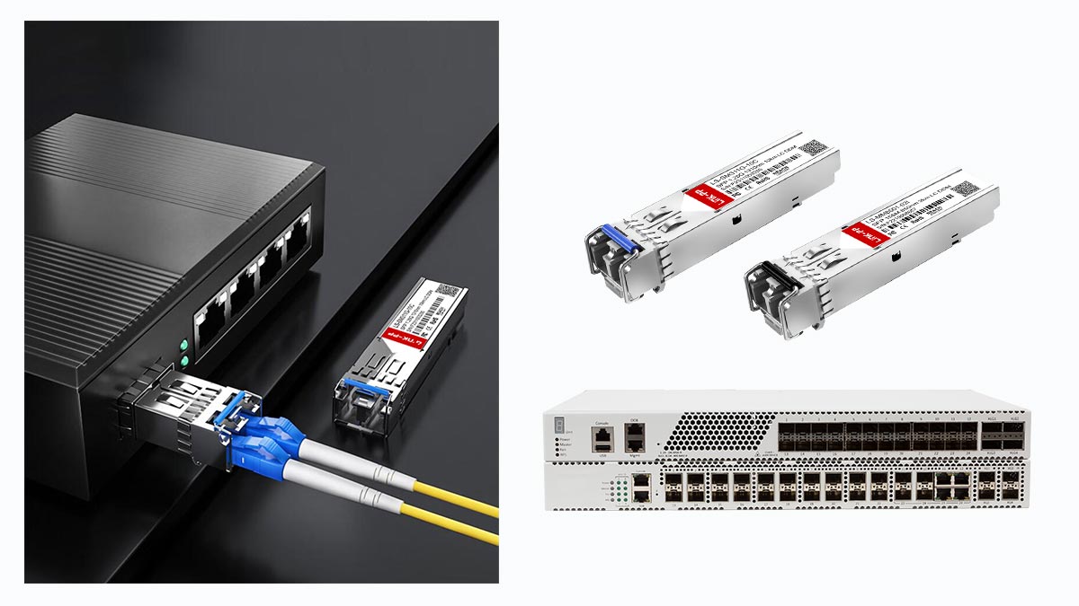
★ Connector Type
Most SFP modules use a duplex LC connector, but other interface types may exist depending on the application.
Common connector types include:
Connector | Description |
|---|---|
LC Duplex | Most common for SFP and SFP+ modules |
SC | Older fiber infrastructure |
RJ45 | Copper Ethernet SFP modules |
Ensuring the correct connector type helps avoid physical compatibility issues with fiber patch cables.
★ Applications
Recommended SFP Modules for Common Applications
Application | Recommended SFP |
|---|---|
Data center short-range links | 10GBASE-SR SFP+ |
Building-to-building fiber links | 10GBASE-LR SFP+ |
Long-distance metro networks | 10GBASE-ER SFP+ |
Legacy Gigabit Ethernet networks | 1000BASE-SX / LX SFP |
High-speed server connections |
By evaluating these factors—speed, fiber type, distance, wavelength, and connector type—network engineers can accurately determine which SFP module is best suited for a specific network deployment.
Choosing the correct transceiver not only ensures reliable optical communication but also simplifies SFP troubleshooting and compatibility verification during network operations.
➡️ Common Problems When Checking SFP Modules
When engineers check SFP modules during network troubleshooting, several common problems frequently appear. Many of these issues are widely discussed in network engineering communities and forums because they can cause link failures, unstable connections, or incorrect diagnostics readings.
Understanding these common problems can help administrators identify SFP issues faster and resolve fiber connectivity problems more efficiently.
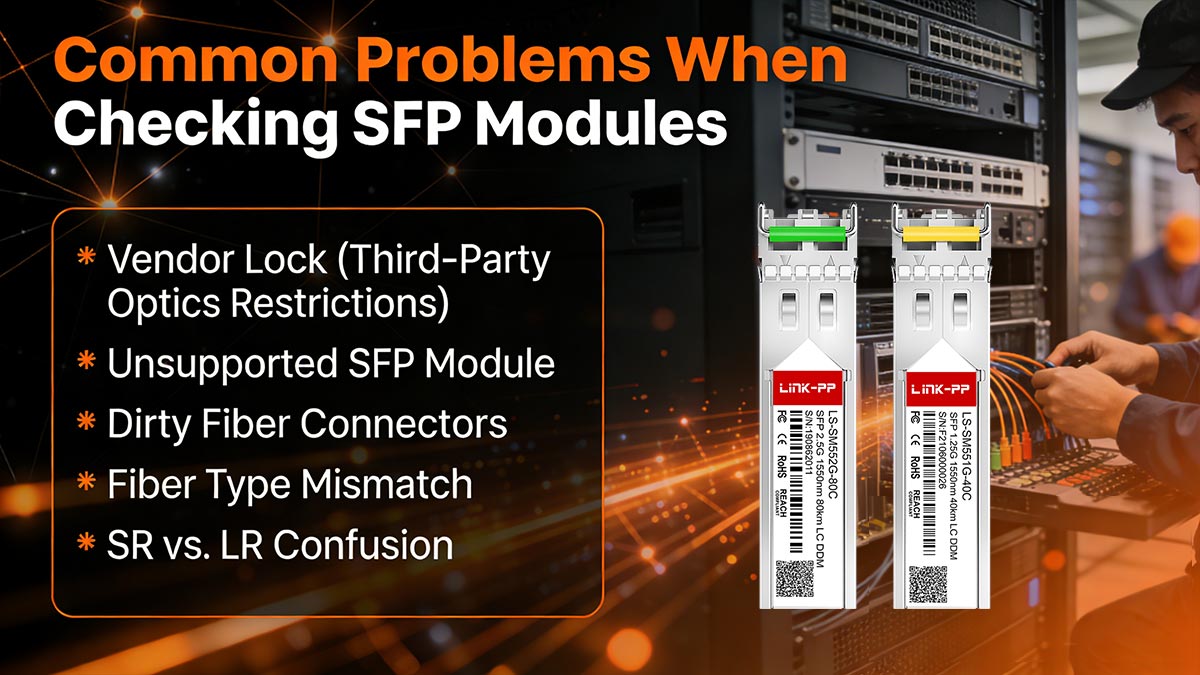
Vendor Lock (Third-Party Optics Restrictions)
Some network equipment vendors implement vendor lock mechanisms that restrict the use of third-party optical modules. When a switch detects an unsupported transceiver, it may display warning messages or disable the port entirely.
Typical symptoms include:
Switch reports “unsupported transceiver”
Interface remains down despite correct fiber connections
Warning logs indicating non-approved optics
In many cases, administrators must either use vendor-approved SFP modules or enable compatibility settings if supported by the device.
Unsupported SFP Module
Another common issue is installing an SFP module that the switch does not recognize or support.
Possible causes include:
Firmware limitations
Incorrect module type (SFP vs. SFP+)
Incompatible speed configuration
For example, installing a 10G SFP+ module in a 1G-only SFP port may result in the module not being detected or the interface remaining inactive.
Dirty Fiber Connectors
Dust and contamination on fiber connectors are among the most frequent causes of optical link failures.
Even microscopic particles on the connector surface can significantly reduce signal strength and lead to:
Low RX optical power
High packet loss
Intermittent link drops
Cleaning fiber connectors using proper fiber cleaning tools is often the fastest way to resolve unexpected SFP link issues.
Fiber Type Mismatch
Using the wrong fiber type with a specific SFP module can prevent the optical link from working correctly.
Common mismatches include:
For example, connecting multimode fiber to an LR single-mode SFP can result in weak signal levels or no link detection.
SR vs. LR Confusion
Another frequent problem occurs when engineers mistakenly install different optical standards on each end of the fiber link.
For instance:
One side uses 10GBASE-SR
The other side uses 10GBASE-LR
Because these modules operate at different wavelengths (850 nm vs. 1310 nm), the optical signals will not communicate correctly. Both ends of the link must use matching optical standards.
DOM / DDM Diagnostics Not Supported
Some SFP modules do not support Digital Optical Monitoring (DOM or DDM), which means the switch cannot read diagnostic values such as temperature, TX power, or RX power.
When this happens:
Optical diagnostic commands may return no data
Monitoring tools cannot analyze link health
Troubleshooting becomes more difficult
In environments that require detailed monitoring, engineers typically deploy DOM-capable SFP modules to ensure full diagnostic visibility.
Recognizing these common issues makes it much easier to check SFP modules and perform effective SFP troubleshooting. In many cases, problems can be resolved quickly by cleaning connectors, verifying fiber type, confirming module compatibility, or replacing faulty transceivers.
➡️ Quick SFP Module Check Checklist
When troubleshooting fiber links, network engineers often follow a quick SFP module check process to identify potential issues before performing deeper diagnostics. A structured checklist helps quickly determine whether the problem is related to the SFP transceiver, fiber cabling, or switch configuration.
This simple SFP troubleshooting checklist can be used during network installation, maintenance, or when a link unexpectedly goes down.
Step-by-Step SFP Module Check
✔ Confirm the SFP module type
Verify the installed module type and specifications, including speed (1G / 10G / 25G), optical standard (SR / LR / ER), and wavelength. Using the wrong module type is a common cause of link failures.
✔ Check switch compatibility
Ensure that the SFP module is supported by the switch or router. Some devices restrict unsupported optics or third-party modules, which can prevent the port from activating.
✔ Verify fiber type
Confirm that the fiber cable matches the SFP specification.
SR modules → Multimode fiber (OM3 / OM4)
LR modules → Single-mode fiber
A mismatch between fiber type and SFP module can result in weak optical signals or no link.
✔ Read optical diagnostics (DOM/DDM)
Use switch CLI commands to read SFP diagnostic values, including:
Temperature
Voltage
TX optical power
RX optical power
Abnormal values often indicate signal loss, fiber attenuation, or hardware problems.
✔ Inspect and clean fiber connectors
Check LC connectors and fiber patch cables for dust, scratches, or contamination. Dirty connectors are one of the most common causes of low RX optical power and unstable fiber links.
✔ Swap the SFP module if necessary
If the link still fails after these checks, replace the SFP module with a known-working transceiver. This helps determine whether the issue originates from the module or another network component.
Following this quick SFP module checklist allows network engineers to diagnose most fiber connectivity issues within minutes. In many cases, simple steps such as verifying compatibility, cleaning connectors, or replacing a faulty SFP can restore normal network operation without complex troubleshooting.
➡️ FAQs About Checking SFP Modules
Below are some frequently asked questions about checking SFP modules, testing optical transceivers, and identifying the correct SFP for a network deployment.
1. How to check SFP?
To check an SFP module, network engineers typically verify both the physical installation and the diagnostic information provided by the network device.
The basic process includes:
Confirm the SFP module is properly inserted into the switch port
Check interface link status on the switch
Use CLI commands to read SFP diagnostics (DOM/DDM)
Verify the fiber type and cable connections
Inspect and clean fiber connectors if necessary
These steps help determine whether the issue is related to the SFP module, fiber cable, or network configuration.
2. How to check SFP on a Cisco switch?
On Cisco switches, administrators can check SFP status using several CLI commands.
Common commands include:
show interface status
show inventory
show interfaces transceiver
show interfaces transceiver detail
These commands allow engineers to:
Verify whether the SFP module is detected
Identify the transceiver model and vendor
Read optical diagnostic data such as temperature, voltage, TX power, and RX power
This information is essential for SFP diagnostics and troubleshooting.
3. How to test an SFP module?
Testing an SFP module usually involves a step-by-step verification process.
Typical testing steps include:
Perform a physical inspection of the module and fiber connectors
Check link status on the switch interface
Read DOM/DDM optical diagnostics values
Verify fiber type and wavelength compatibility
Replace the module with a known-working SFP to isolate the issue
This approach helps determine whether the SFP module itself is faulty or if the problem is caused by the fiber infrastructure or switch port.
4. How to know what SFP module to use?
Selecting the correct SFP module depends on several network parameters:
Speed — 1G, 10G, or 25G
Fiber type — multimode fiber (MMF) or single-mode fiber (SMF)
Transmission distance — short, medium, or long reach
Wavelength — typically 850 nm, 1310 nm, or 1550 nm
Connector type — most commonly LC duplex
For example:
10GBASE-SR SFP+ → multimode fiber, short distance (data center links)
10GBASE-LR SFP+ → single-mode fiber, up to 10 km connections
Matching these parameters ensures stable fiber connectivity and compatibility with network equipment.
➡️ Conclusion: How to Check and Verify SFP Modules Efficiently
Checking an SFP module is an essential task for maintaining stable fiber-optic network connectivity. Because SFP transceivers operate at the physical layer of the network, any issue with the module—such as incorrect installation, optical signal loss, or compatibility problems—can immediately affect link performance.
By following a structured process, network engineers can quickly diagnose and verify SFP modules. This typically includes checking interface status on the switch, reviewing SFP diagnostics (DOM/DDM data) such as temperature and optical power, and confirming that the module matches the correct fiber type, transmission distance, and wavelength requirements.
Equally important is ensuring compatibility between the SFP module and the network equipment. Using the correct module type—whether 1G SFP, 10G SFP+, or 25G SFP28—and matching the proper optical standard (such as SR or LR) helps prevent unsupported module errors and link failures.
When issues occur, effective SFP troubleshooting often involves verifying fiber connections, cleaning connectors, and replacing the module with a known-working transceiver to isolate the root cause.
By combining diagnostic monitoring, compatibility checks, and systematic troubleshooting, engineers can efficiently identify problems and maintain reliable fiber network performance.
For reliable and cost-effective optical connectivity, you can explore compatible SFP and SFP+ transceivers at the LINK-PP Official Store, designed to support a wide range of enterprise switches, routers, and data center networking environments.


