

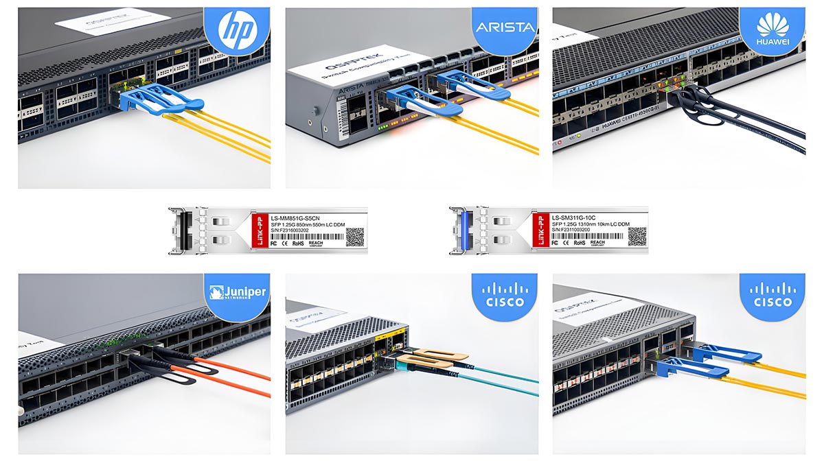
Small Form-factor Pluggable (SFP) compatibility determines whether an optical transceiver can operate reliably within a specific network device without firmware rejection or performance limitations. While SFP modules follow standardized electrical and optical specifications, compatibility is often influenced by vendor firmware policies, EEPROM identification fields, and digital diagnostic implementation.
Understanding how SFP compatibility works is critical for network engineers, system integrators, and procurement teams. Incorrect module selection can result in “unsupported transceiver” errors, link instability, or monitoring failures. This guide explains how compatibility is technically determined, how to test it step by step, and how EEPROM coding impacts vendor interoperability.
🔴 What Is SFP Compatibility?
SFP compatibility refers to whether a SFP transceiver can operate correctly in a specific network device without firmware rejection, hardware conflicts, or functional limitations. Compatibility is not determined by form factor alone; it depends on electrical signaling compliance, protocol support, firmware validation logic, and EEPROM identification fields defined by industry standards.
Although SFP modules follow Multi-Source Agreement (MSA) specifications, two modules with identical optical parameters (e.g., 10GBASE-LR, 1310 nm, 10 km) may behave differently in a given switch or router. This is because compatibility is enforced at multiple technical layers—not just the physical connector.
Below are the four primary dimensions that determine SFP compatibility.
1. Electrical Compatibility
Electrical compatibility ensures that the transceiver meets the host device’s signaling, voltage, and power requirements.
SFP and SFP+ modules must comply with the electrical interface specifications defined in:
SFF-8431 (SFP+ 10 Gb/s electrical interface)
SFF-8472 (Digital Diagnostics Monitoring interface extensions)
Electrical compatibility includes:
Supported data rate (1G, 10G, 25G, etc.)
Transmit (Tx) and Receive (Rx) differential signaling levels
Power supply voltage tolerance (typically 3.3 V)
Maximum module power consumption
I²C management interface compliance
If a module exceeds the host’s power budget or does not meet the required signal integrity parameters, it may fail initialization or cause link instability—even if the optics are correct.
Electrical compatibility is therefore the first gating factor before optical link establishment occurs.
2. Protocol Compatibility
Protocol compatibility refers to whether the module supports the Ethernet or Fibre Channel standard expected by the host device.
For example:
A 1000BASE-SX module must comply with IEEE 802.3z
A 10GBASE-LR module must comply with IEEE 802.3ae
Even if two modules share the same wavelength (e.g., 1310 nm), they are not interchangeable unless they support the same modulation, encoding, and line rate defined by the applicable IEEE clause.
Protocol compatibility also includes:
Auto-negotiation behavior (where applicable)
Forward Error Correction (FEC) expectations (in higher-speed modules)
Link training requirements (in SFP28 and beyond)
A protocol mismatch typically results in no link establishment, even when the transceiver is recognized by the system.
3. Vendor Firmware Recognition
Modern network equipment often implements firmware-level validation of inserted transceivers. During initialization, the device reads identification data via the I²C interface and compares it against internal approval tables.
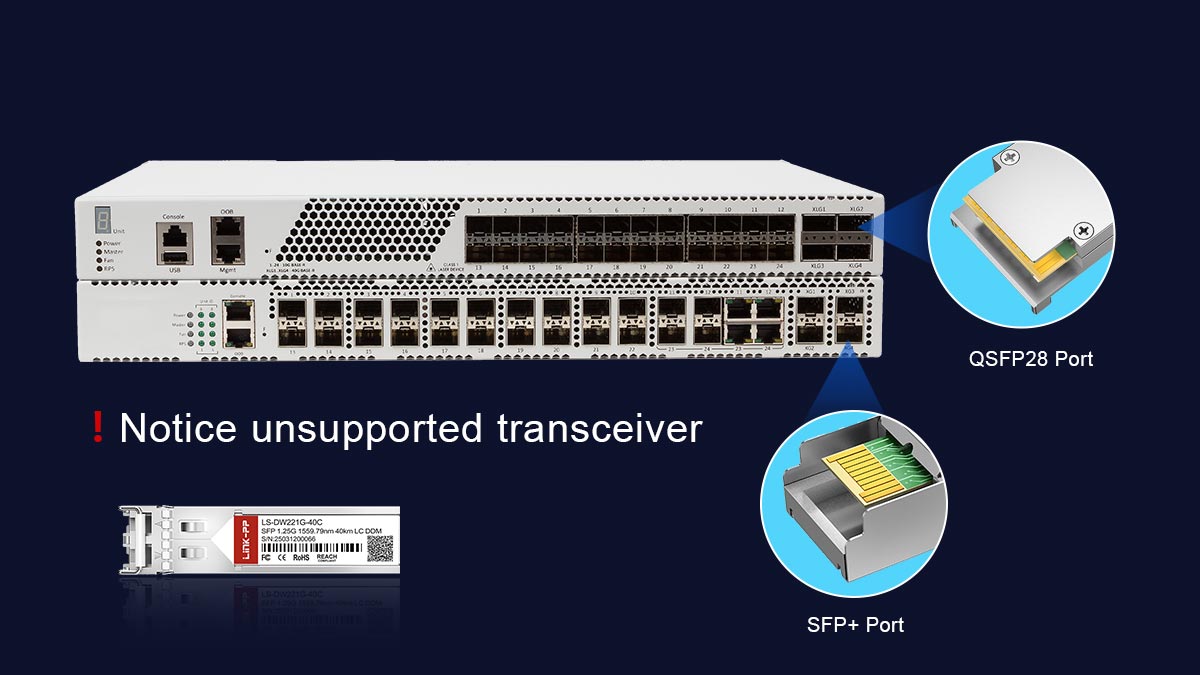
If the module’s identification does not match expected vendor criteria, the device may:
Display “Unsupported transceiver” warnings
Disable the port (err-disabled state)
Block DOM monitoring
Log compliance errors
This mechanism is sometimes referred to as vendor locking or transceiver validation enforcement. It does not necessarily indicate a hardware incompatibility; instead, it reflects firmware policy decisions implemented by the system vendor.
From an engineering perspective, vendor recognition occurs before traffic forwarding and is independent of optical performance. A module may be electrically and optically compliant yet still rejected due to firmware policy.
4. EEPROM Identification and Memory Map
All SFP modules contain an EEPROM memory device accessible via the two-wire serial interface (I²C). The memory structure is standardized under the SFP MSA and extended by:
SFF-8472
Key EEPROM fields include:
Vendor Name
Vendor OUI (Organizationally Unique Identifier)
Part Number
Serial Number
Supported Data Rate
Wavelength
Diagnostic capability flags
When a module is inserted, the host system reads these memory addresses to determine:
Module type
Supported speed
Optical characteristics
Diagnostic monitoring availability
If the EEPROM data format is invalid, checksum values fail, or the vendor identifier does not match firmware expectations, the module may be rejected—even if the hardware itself is functional.
Therefore, EEPROM identification acts as the logical identity layer of SFP compatibility.
Compatibility vs. Interoperability
It is important to distinguish compatibility from interoperability:
Compatibility determines whether the host system accepts and initializes the module.
Interoperability determines whether two connected modules can establish and maintain a stable optical link.
A module can be compatible with a switch but fail interoperability due to wavelength mismatch, insufficient link budget, or protocol inconsistency on the remote side.
Both dimensions must be validated during deployment.
SFP compatibility is a multi-layer validation process involving:
Electrical compliance with MSA specifications
Protocol adherence to IEEE Ethernet or Fibre Channel standards
Firmware-level vendor recognition
Proper EEPROM identification structure
Because compatibility spans physical, logical, and firmware domains, verification should include both specification review and practical validation within the target device.
Understanding these layers reduces deployment risk, prevents firmware rejection events, and ensures predictable network operation in multi-vendor environments.
🔴 Why Are Some SFP Modules Not Compatible?
Even when two SFP modules share the same form factor and nominal data rate, they may not function correctly in the same host device. SFP incompatibility is rarely caused by mechanical issues; instead, it typically results from firmware validation logic, EEPROM identification mismatches, electrical constraints, or optical parameter inconsistencies.
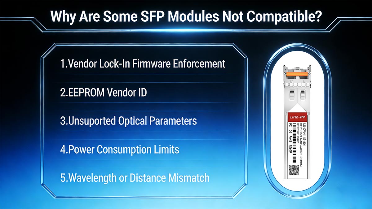
Below are the five primary technical reasons why an SFP module may be rejected or fail to operate properly in a given switch, router, or server NIC.
1️⃣ Vendor Lock-In Firmware Enforcement
Many network equipment manufacturers implement firmware-level transceiver validation. When an SFP module is inserted, the host reads its EEPROM data via the I²C interface and compares vendor-specific identification fields against an internal approval database.
If the module does not match approved identifiers, the system may:
Display an “Unsupported transceiver” warning
Disable the interface (err-disabled state)
Block digital diagnostics monitoring (DOM)
Log a compliance or security event
This mechanism is commonly referred to as vendor lock-in. It is not defined by IEEE Ethernet standards but implemented at the firmware level by individual equipment vendors.
From an engineering standpoint, vendor lock enforcement occurs after physical insertion but before full port activation. A module may be electrically and optically compliant with the relevant IEEE clause yet still be rejected due to firmware policy.
2️⃣ EEPROM Vendor ID or Memory Map Mismatch
All SFP modules include an EEPROM memory device structured according to the SFP Multi-Source Agreement (MSA).
If any of the following occur, compatibility may fail:
Invalid checksum values
Corrupted or incomplete memory map
Non-compliant formatting of identification fields
Vendor OUI not recognized by firmware
Because many switches rely on EEPROM parsing during initialization, incorrect or non-standard memory encoding can cause immediate rejection—even when the optical hardware is functional.
EEPROM validation is therefore a logical compatibility gate independent of optical performance.
3️⃣ Unsupported Optical Parameters
Even if a module is physically recognized, it must match the optical characteristics expected by the host interface.
For example:
A 10GBASE-LR module must comply with IEEE 802.3ae
A 1000BASE-SX module must comply with IEEE 802.3z
Incompatibility can occur if:
The module’s nominal data rate differs from the port’s supported rate
The modulation format does not match (e.g., Ethernet vs Fibre Channel)
The required Forward Error Correction (FEC) mode is unsupported
The optical budget does not meet the link requirement
A common misconception is that wavelength alone determines compatibility. In reality, compliance with the full IEEE clause—including encoding, jitter tolerance, extinction ratio, and receiver sensitivity—is required.
If optical parameters fall outside the expected specification window, the link may fail to establish or exhibit instability.
4️⃣ Power Consumption Limits
Each SFP port has a defined maximum power allowance. Exceeding this limit can prevent proper initialization or cause thermal alarms.
Electrical and power specifications for SFP+ modules are defined in:
SFF-8431
Typical SFP power classes include:
Class 1: ≤ 1.0 W
Class 2: ≤ 1.5 W
Class 3: ≤ 2.0 W
Higher-speed or extended-reach modules (e.g., ER or ZR variants) often consume more power due to stronger laser output or additional signal conditioning circuitry.
If a module draws more current than the host port supports:
The module may fail to initialize
The port may shut down for protection
Temperature warnings may appear in diagnostics
Power incompatibility is especially relevant in high-density switch platforms where thermal and electrical margins are tightly controlled.
5️⃣ Wavelength or Distance Mismatch
Optical compatibility also depends on wavelength alignment and link design constraints.
Examples of mismatch scenarios:
A 1310 nm module connected to an 850 nm multimode module
A short-reach (SR) module used over long single-mode fiber
An extended-reach (ER) module used without appropriate attenuation
Even when two modules share the same data rate, they must:
Operate at the same nominal wavelength
Support the same fiber type (SMF vs. MMF)
Provide compatible transmit power and receiver sensitivity
Distance rating alone does not determine compatibility. Instead, engineers must verify that the total link budget satisfies:
Tx(min) − Total Fiber Loss ≥ Rx(sensitivity)
If wavelength or optical budget requirements are not aligned, the link may not establish or may experience high bit error rates.
Engineering Perspective
SFP incompatibility is typically caused by one or more of the following technical layers:
Firmware-level vendor enforcement
EEPROM identification mismatch
IEEE standard or protocol inconsistency
Electrical power constraints
Optical wavelength or link budget mismatch
Because compatibility spans firmware, electrical, and optical domains, validation should include both specification review and live testing within the target platform.
Understanding these failure mechanisms allows engineers to diagnose “unsupported transceiver” events systematically rather than attributing them solely to brand differences.
🔴 How SFP Compatibility Is Determined (Technical Layer)
SFP compatibility is determined through a combination of electrical, logical, and firmware-level mechanisms that operate before an optical link is fully established. Engineers must understand how the host device communicates with the transceiver, verifies identification, and evaluates digital diagnostics to ensure proper operation. The process primarily involves the I²C interface, the EEPROM memory map, Digital Optical Monitoring (DOM) data, and vendor identification fields such as the Organizationally Unique Identifier (OUI).
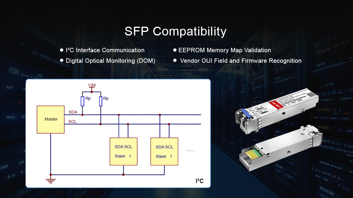
▶ I²C Interface Communication
All SFP modules incorporate a two-wire serial interface (I²C) for communication with the host system. This interface is standardized under the SFP Multi-Source Agreement (MSA) and extended in SFF-8472 for Digital Diagnostics Monitoring.
Key functions of the I²C interface include:
Reading and writing the EEPROM memory map
Accessing digital diagnostic data (temperature, voltage, optical power)
Verifying module type and operational class before initialization
The host device polls the I²C interface immediately after insertion. If the module does not respond correctly or returns invalid data, the device may flag it as incompatible, preventing traffic forwarding even if the physical and optical specifications are compliant.
▶ EEPROM Memory Map Validation
The EEPROM contains structured fields that define the module’s identity and capabilities. Its organization is defined by SFF-8472 and SFF-8431 standards. Critical memory sections include:
Memory Address | Field | Description |
|---|---|---|
0x00–0x0F | Identifier & Extended Identifier | Module type (e.g., SFP, SFP+) |
0x10–0x17 | Vendor Name | Manufacturer name |
0x18–0x1F | Vendor OUI | Organizationally Unique Identifier (3 bytes) |
0x20–0x35 | Vendor Part Number | Module model number |
0x36–0x3B | Vendor Revision | Hardware revision or version |
0x3C–0x3F | Serial Number | Unique module identifier |
0x40–0x4F | Date Code | Manufacture date |
0x50–0x5F | Diagnostic Flags | DOM capability and supported features |
0x60–0x7F | Reserved / Vendor-specific | Extended data fields |
The host system reads these addresses to:
Confirm the module type matches the expected interface (e.g., 1G vs 10G)
Validate manufacturer identity via the OUI
Determine module revision and part number for firmware validation
Check for diagnostic support if DOM monitoring is required
If the EEPROM data is invalid or the checksum fails, the module may be rejected even if the optical and electrical specifications are compatible.
▶ Digital Optical Monitoring (DOM)
Digital Optical Monitoring provides real-time measurement of key operating parameters such as:
Transmit optical power (Tx)
Receive optical power (Rx)
Module temperature
Supply voltage
Laser bias current
DOM data is stored in the EEPROM and accessible via the I²C interface. When the host queries these values, it can determine:
Whether the module operates within specification
If the optical link can support the expected distance
Whether thermal or voltage conditions are acceptable
DOM verification also plays a role in compatibility validation. Some systems require DOM support for advanced monitoring; modules lacking it may be flagged as incompatible, even if they are electrically and optically correct.
▶ Vendor OUI Field and Firmware Recognition
The Organizationally Unique Identifier (OUI) in the EEPROM identifies the manufacturer. Many network devices use this field to enforce firmware-level compatibility policies:
Modules from unrecognized vendors may be rejected
OEM-approved modules are prioritized for traffic forwarding
DOM data may be disabled if the OUI is not recognized
This layer is independent of physical or optical performance. Correct OUI identification is crucial for modules to pass firmware validation checks before the link is activated.
Determining SFP compatibility involves:
Electrical signaling verification via SFF-8431 standards
EEPROM memory map validation for module identity, revision, and diagnostics
DOM data access to confirm operational integrity and optical parameters
Vendor OUI recognition to enforce firmware compatibility
By understanding these technical layers, engineers can systematically verify whether a transceiver will function reliably in a specific device and avoid unexpected “unsupported transceiver” events.
References (Standards & Specifications)
SFF-8472 — Digital Diagnostic Monitoring for Optical Transceivers
SFF-8431 — SFP+ 10 Gb/s Electrical Interface Specification
SFF-8432 — SFP Module Specification (EEPROM memory map)
🔴 How to Test SFP Compatibility (Step-by-Step)
Ensuring that an SFP module is fully compatible with a network device requires a structured, engineer-verified process. The following step-by-step guide combines specification review, firmware verification, and live testing to confirm both recognition and reliable operation. This methodology minimizes the risk of “unsupported transceiver” events and link instability in production networks.
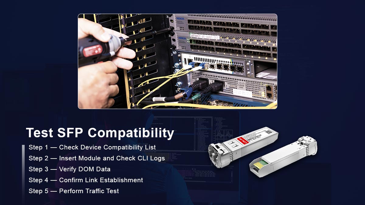
Step 1 — Check Device Compatibility List
Before physically inserting a module, consult the host device’s approved transceiver compatibility list. Most switch and router vendors publish this list in technical documentation or release notes.
What to verify:
Supported data rates (1G, 10G, 25G, 100G)
Firmware version requirements
Any restrictions on third-party modules
Why it matters:
Modules not explicitly listed may be rejected by firmware, even if their electrical and optical parameters meet standards. This step eliminates compatibility issues caused by vendor lock-in at the firmware level.
Step 2 — Insert Module and Check CLI Logs
Physically insert the SFP module into the target port. Immediately monitor the device logs using CLI commands to ensure recognition.
Common CLI commands:
show interface transceiver
show inventory
show logging
What to look for:
Module is detected without errors
No “unsupported transceiver” warnings
Correct module type, vendor, and serial number are reported
Engineering note:
Firmware-level rejection often occurs during initialization. Log entries provide an early indication of EEPROM issues, vendor OUI mismatch, or unsupported data rates.
Step 3 — Verify DOM Data
Digital Optical Monitoring (DOM) allows engineers to confirm that the module is operating within electrical and optical parameters.
Steps:
Read DOM data via I²C interface or CLI commands:
show interface transceiver detailsVerify key metrics:
Parameter | Expected Range |
|---|---|
Tx Optical Power | Within module spec (dBm) |
Rx Optical Power | Within receiver sensitivity (dBm) |
Module Temperature | Manufacturer rated operating range (°C) |
Supply Voltage | 3.135–3.465 V (typical SFP+) |
Laser Bias Current | Within allowed current limit |
Why it matters:
Even a recognized module may fail in operation if Tx/Rx levels or power supply readings are out of range. DOM verification ensures electrical and optical parameters meet the host’s requirements.
Step 4 — Confirm Link Establishment
After module recognition and DOM verification, confirm that the optical link is established and stable.
Steps:
Connect the SFP module to the corresponding remote port
Verify the link status using CLI:
show interface status
show interface counters errors
Check for:
Active link state
No excessive link flaps
No CRC or alignment errors
Engineering note:
Link establishment confirms both electrical and optical interoperability. A module may be compatible with the host but fail interoperability due to wavelength mismatch, fiber type mismatch, or distance exceeding link budget.
Step 5 — Perform Traffic Test
Finally, validate real-world performance by sending traffic through the module.
Steps:
Use a traffic generator or production traffic (with caution)
Measure:
Throughput consistency
Packet loss
Error counters
Why it matters:
Traffic testing is the ultimate verification. Even modules that pass EEPROM checks and DOM metrics can fail under sustained load if electrical signaling or optical parameters are marginal.
Engineering tip:
For multi-vendor deployments, repeat the traffic test with different combinations of SFP modules and host ports to ensure full interoperability.
Summary of Step-by-Step Testing
Step | Purpose |
|---|---|
1. Check device compatibility list | Avoid firmware-level rejection |
2. Insert module and check CLI logs | Verify recognition and vendor ID |
3. Verify DOM data | Confirm optical/electrical parameters |
4. Confirm link establishment | Validate interoperability and link stability |
5. Perform traffic test | Ensure real-world operational performance |
🔴 Common SFP Compatibility Errors and Troubleshooting
Even when an SFP module meets electrical and optical specifications, deployment issues can arise due to firmware, EEPROM, or operational mismatches. Understanding the most frequent compatibility errors and their causes is essential for engineers to diagnose and resolve problems efficiently. Below are the key error types and their technical explanations.
♦ Unsupported Transceiver
Description:
The host device detects the module but refuses to activate the port, often displaying an “unsupported transceiver” message.
Technical Cause:
Vendor firmware validation fails due to unrecognized OUI or part number
EEPROM fields do not match the host’s approved transceiver database
Implication:
The module may be electrically and optically compliant, but the port remains inactive until a supported module is installed or firmware override is applied.
♦ Err-Disabled
Description:
The port is administratively or automatically placed into an error-disabled state immediately after module insertion.
Technical Cause:
Power consumption exceeds port limits
Electrical signal quality does not meet SFF-8431 or IEEE standards
Firmware detects an unsafe condition (e.g., thermal overrun)
Implication:
The interface is shut down to protect hardware. Engineers must investigate logs and metrics before re-enabling the port.
♦ Link Flap
Description:
The link repeatedly goes up and down, causing intermittent connectivity.
Technical Cause:
Wavelength mismatch between transmitter and receiver
Inadequate optical link budget (distance or fiber loss issues)
Marginal Tx/Rx signal levels detected by DOM
Implication:
Even recognized and compatible modules can experience instability if optical conditions are not met. Adjusting fiber type, module reach, or signal power is often required.
♦ No DOM Data
Description:
The fiber module is recognized and the link is active, but the system cannot read Digital Optical Monitoring values.
Technical Cause:
Module lacks DOM capability or EEPROM flags are incorrectly set
I²C interface communication issues
Firmware disables DOM for unapproved vendors
Implication:
Engineers lose real-time visibility of key parameters such as Tx/Rx power, temperature, or supply voltage. While traffic may continue to pass, monitoring and troubleshooting become difficult.
♦ Note
These errors can be systematically diagnosed by combining:
CLI log inspection (
show interface transceiver,show inventory)DOM verification (
show interface transceiver details)Cross-checking module EEPROM memory map (SFF-8472)
Confirming electrical and optical parameters against SFF-8431 and IEEE standards
Understanding these error mechanisms allows network engineers to isolate firmware, electrical, and optical issues efficiently, ensuring reliable SFP deployment.
🔴 Vendor Locking and Third-Party SFPs
In the networking industry, the term vendor locking refers to mechanisms that restrict the use of optical transceivers to modules officially approved by the equipment manufacturer. This practice affects compatibility and operational behavior, but it is important to understand it from an engineering perspective without implying value judgments.

Vendor Restrictions
Some network equipment vendors implement firmware checks that verify the module’s EEPROM fields, including the Organizationally Unique Identifier (OUI), part number, and revision. If the module does not match an approved vendor profile, the device may:
Display “unsupported transceiver” messages
Disable the port or place it in an err-disabled state
Restrict access to Digital Optical Monitoring (DOM) data
These restrictions are not dictated by IEEE or SFF standards; rather, they are vendor-specific firmware policies designed to ensure that only modules meeting the vendor’s tested specifications are accepted.
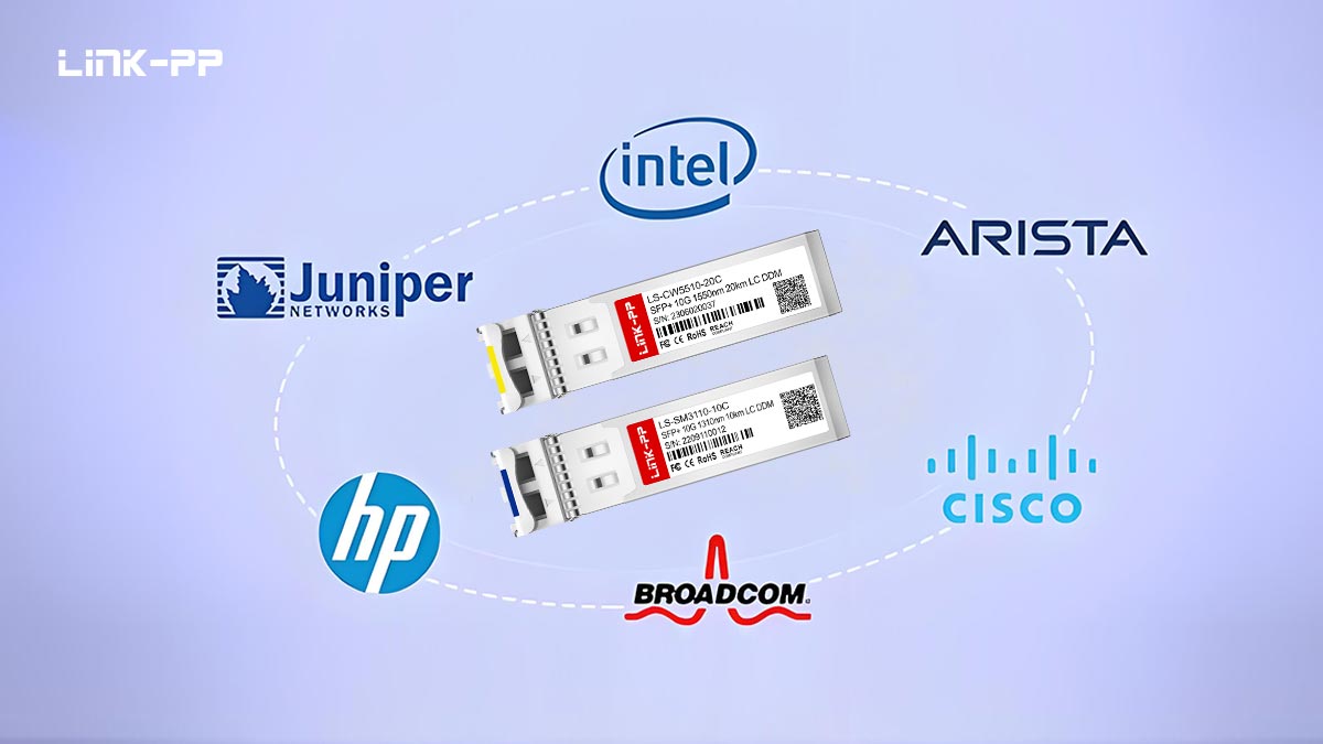
Third-Party SFP Support
Other vendors allow third-party or multi-vendor modules to operate in their devices, provided they comply with the required electrical, optical, and protocol specifications. In these cases:
The module may be recognized and activated immediately
DOM monitoring is fully supported
Performance and interoperability can match first-party modules if specifications align
Supporting third-party modules reduces dependency on a single supplier and can provide cost flexibility, but engineers must verify that the modules meet the host’s exact requirements.
Coding and Compatibility Services
To bridge compatibility gaps, several engineering services exist that reprogram EEPROM fields to match vendor expectations. These services can adjust:
Vendor OUI and part number fields
Revision codes and feature flags
DOM capability flags
Such coding services allow otherwise compliant optical modules to be recognized by systems with stricter firmware enforcement. From a technical standpoint, this does not alter the module’s electrical or optical performance; it only modifies identification metadata to satisfy firmware validation logic.
🔴 SFP Compatibility Validation Checklist
Ensuring SFP optical modules function reliably in a network device requires systematic verification across electrical, optical, and firmware layers. The following checklist provides a concise, engineer-verifiable procedure to confirm compatibility before deployment. This approach reduces risk of link failure, err-disabled ports, or unsupported transceiver errors.
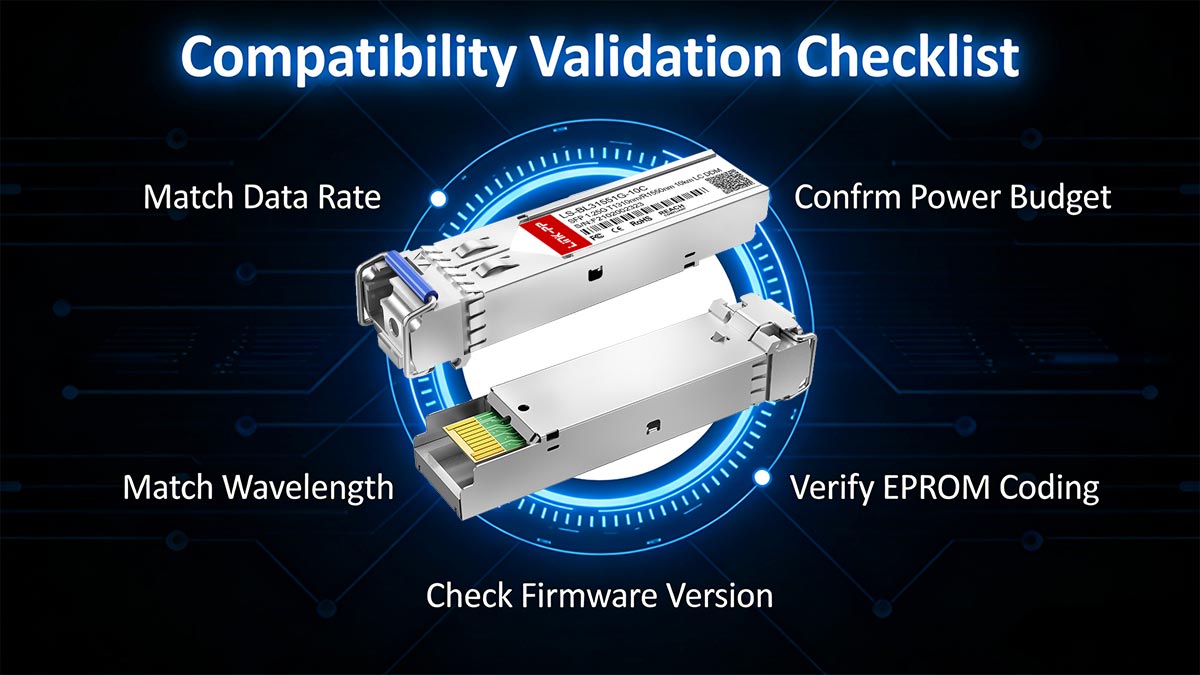
1. Match Data Rate
Verify that the SFP module supports the same data rate as the host port (e.g., 1G, 10G, 25G).
Check protocol alignment according to IEEE standards:
1G: IEEE 802.3z
10G: IEEE 802.3ae
Data rate mismatch can prevent link establishment even if electrical and optical parameters are correct.
2. Match Wavelength
Confirm that the module’s transmitter wavelength corresponds to the fiber type and remote module:
SR modules: 850 nm (multimode)
LR/ER modules: 1310 nm or 1550 nm (single-mode)
Wavelength mismatch leads to insufficient optical power at the receiver and high bit error rates.
3. Confirm Power Budget
Ensure the module’s Tx optical power minus the total link loss meets the receiver sensitivity:
Tx(min)−Total Link Loss≥Rx(sensitivity)Include all fiber attenuation, connector loss, and splice loss in calculations.
Check DOM readings for Tx/Rx power to verify operational margins.
4. Verify EEPROM Coding
Confirm that EEPROM fields comply with MSA and vendor expectations (SFF-8472):
Vendor OUI and Name
Part Number
Revision/Feature flags
Checksum validation
Incorrect coding can cause firmware rejection even if the module meets electrical and optical specifications.
5. Check Firmware Version
Verify that the host device firmware supports the inserted module.
Some modules require minimum firmware versions to support advanced features such as DOM or extended reach.
Outdated firmware may result in unsupported transceiver warnings or partial feature availability.
Engineering Note
Completing this checklist ensures that an SFP module is electrically compliant, optically compatible, firmware-recognized, and fully operational. For multi-vendor environments, repeat these checks for each module type and deployment scenario to maintain network stability and predictability.
🔴 SFP Compatibility Recommendations
From an engineering and network reliability perspective, SFP compatibility should be treated as a validation process—not an assumption. The following recommendations help reduce deployment risk and long-term operational instability.
1. Always Validate Before Deployment
Perform lab testing before large-scale rollout.
Confirm link establishment, DOM readings, and error counters.
Validate interoperability in real switch/router environments under expected traffic loads.
Record baseline optical power, temperature, and bias current values for future troubleshooting reference.
Pre-deployment validation significantly reduces field failures and unexpected firmware-triggered restrictions.
2. Avoid Mixed Wavelength Configurations
Do not mix 850 nm (SR) and 1310/1550 nm (LR/ER) modules on the same fiber link.
Ensure both ends of the link use identical wavelength and reach class.
For BiDi deployments, verify matched wavelength pairs (e.g., 1310 nm TX / 1550 nm RX on one side, reversed on the other).
Wavelength mismatches are one of the most common causes of “link up but unstable” or complete link failure scenarios.
3. Maintain Firmware Consistency
Standardize firmware versions across identical switch platforms.
Avoid mixing firmware builds within the same network segment.
Review release notes before upgrading to identify changes affecting transceiver validation policies.
Firmware consistency prevents unpredictable behavior such as sudden “unsupported transceiver” errors after updates.
Engineering Summary
Reliable SFP deployment requires alignment across four layers:
Electrical compliance
Optical power budget
EEPROM identification
Host firmware validation
By systematically verifying these factors, engineers can maintain predictable link performance and long-term network stability.
For validated, standards-compliant optical modules with multi-vendor compatibility support, visit the LINK-PP Official Store for technical specifications and engineering assistance.


