

In modern Ethernet and fiber networks, Small Form-Factor Pluggable (SFP) transceivers play a critical role in enabling flexible optical connectivity between switches, routers, and servers. However, even in well-designed infrastructures, engineers frequently encounter issues such as SFP modules not being detected, no link light after installation, or unstable fiber connections. These problems can disrupt network performance and require systematic troubleshooting to resolve quickly.
In most cases, SFP-related faults are not caused by the module itself but by factors such as fiber contamination, incorrect cable polarity, incompatible optics, or configuration mismatches. A structured troubleshooting process—starting from basic physical checks and progressing to optical diagnostics—can significantly reduce downtime and prevent unnecessary hardware replacement.
This guide provides a practical, engineer-focused SFP troubleshooting framework that helps identify and resolve common issues including no link, module detection failures, and fiber connectivity problems. It also introduces diagnostic commands used across major enterprise platforms such as Cisco, Juniper, and Brocade to analyze transceiver status and optical power levels.
By reading this guide, you will learn how to:
Diagnose SFP modules that are not detected by network devices
Resolve no link or intermittent fiber connections
Use Digital Optical Monitoring (DOM) data to identify signal problems
Apply vendor-specific CLI commands for deeper diagnostics
Implement preventive practices to improve long-term SFP reliability
Whether you are maintaining a data center network, enterprise switch infrastructure, or fiber backbone, understanding how to troubleshoot SFP modules efficiently is an essential skill for network engineers.
What Is SFP Troubleshooting?
SFP troubleshooting refers to the process of diagnosing and resolving issues related to Small Form-Factor Pluggable (SFP) transceivers used in network switches, routers, and network interface cards (NICs). These compact optical modules enable flexible fiber connectivity, but problems can occur due to hardware, cabling, compatibility, or configuration factors.

When an SFP module does not function correctly, network engineers typically perform a series of checks—including physical inspection, compatibility verification, and optical diagnostics—to determine the root cause of the issue.
Common symptoms of SFP problems include:
SFP module not detected by the device after insertion
No link light or interface remaining down
Link flapping or intermittent network connectivity
Low optical receive (Rx) power warnings in diagnostics
Unsupported transceiver or compatibility errors in system logs
These issues may result from several underlying causes, such as contaminated fiber connectors, incorrect fiber type, incompatible optical modules, switch configuration errors, or hardware failures. Identifying the correct cause is essential for restoring stable network connectivity and avoiding unnecessary equipment replacement.
Quick SFP Troubleshooting Checklist (Step-by-Step)
Before performing advanced diagnostics, network engineers should first follow a structured troubleshooting sequence. Many SFP issues—such as no link, module detection failure, or intermittent connectivity—can be resolved by checking basic physical and configuration factors.

The following step-by-step checklist helps quickly isolate the root cause of common SFP problems.
1. Check Physical Installation
Ensure that the SFP module is fully inserted and securely locked into the port. Improper seating can prevent the switch from detecting the transceiver.
Verify the following:
The module latch or bail clasp is fully closed
The switch port LED indicator shows the expected status
The SFP cage is not bent, loose, or physically damaged
Poor module seating is one of the most common causes of SFP module detection failures.
2. Inspect Fiber Cables and Connectors
Dirty or damaged fiber connectors can significantly reduce optical signal quality and cause link instability or signal loss.
Recommended inspection steps:
Examine fiber connectors using a fiber inspection microscope
Clean the connectors with a fiber cleaning pen or lint-free wipes
Replace damaged or excessively bent patch cords
Even microscopic dust particles can block the optical signal and lead to low RX power warnings or intermittent links.
3. Verify Fiber Type and Wavelength Compatibility
Both ends of the fiber link must use compatible optical transceivers. Mismatched optics are a common cause of link failures.
Parameter | Must Match |
|---|---|
Fiber Type | Single-mode (SMF) vs. Multimode (MMF) |
850 nm / 1310 nm / 1550 nm | |
Speed | 1G / 10G / 25G |
Using incompatible modules or mismatched fiber types may result in no link, unstable connections, or degraded performance.
4. Perform a Loopback Test
A loopback test helps determine whether the issue is related to the SFP module, the switch port, or the external fiber cable.
Procedure:
Connect the Tx (transmit) and Rx (receive) ports using a loopback cable.
Check whether the interface reports an active link.
If the link becomes active, the SFP module and port are functioning correctly, and the problem likely lies in the external fiber path.
Loopback testing is a quick method for isolating hardware faults during network troubleshooting.
5. Check Switch Configuration
In some cases, SFP modules fail to initialize due to incorrect port configuration settings on the switch.
Verify the following configuration parameters:
Port speed settings (for example, 1G vs. 10G)
Auto-negotiation status
Whether the interface is administratively shut down
Misconfigured ports can prevent the SFP module from establishing a link even when the hardware is functioning normally.
Following a structured troubleshooting checklist can significantly reduce the time required to diagnose SFP-related issues. By starting with basic physical checks and gradually moving toward optical diagnostics and configuration verification, engineers can quickly isolate the root cause of most connectivity problems.
In practice, the majority of SFP failures are related to improper module installation, contaminated fiber connectors, incompatible optics, or configuration mismatches. Performing a loopback test and verifying switch settings often helps determine whether the issue originates from the transceiver, fiber link, or network device.
Using this step-by-step checklist as a standard troubleshooting workflow helps ensure faster fault identification, reduced network downtime, and more reliable fiber link performance.
Common SFP Issues and How to Fix Them
Even in well-designed networks, SFP Transceivers may occasionally experience connectivity problems. Understanding the most common SFP issues and their root causes allows engineers to diagnose and resolve failures quickly without unnecessary hardware replacement.

Below are several typical SFP problems and the recommended troubleshooting actions.
SFP Module Not Detected
One of the most frequent problems occurs when the network device fails to recognize the inserted SFP module.
Possible causes
Incompatible SFP module not supported by the switch
Vendor-locked firmware rejecting third-party optics
Corrupted or faulty module EEPROM data
Recommended solutions
Verify the module against the device compatibility matrix
Test the port with a known working SFP module
Review system logs for error messages related to unsupported transceivers
Many enterprise switches from vendors such as Cisco, Juniper, or Brocade will generate log entries when an incompatible SFP is inserted.
No Link Light
Another common issue occurs when the SFP module is detected but the interface remains down with no link indicator.
Possible causes
Reversed fiber polarity (Tx/Rx swapped)
Incorrect fiber type (single-mode vs multimode mismatch)
Damaged or poor-quality fiber patch cord
Recommended solutions
Swap the Tx and Rx fibers to correct polarity
Replace the fiber cable with a known good patch cord
Check Digital Optical Monitoring (DOM) readings to confirm whether optical power is being received
These steps help determine whether the issue is caused by the fiber path or the optical transceiver itself.
Intermittent Link or Link Flapping
In some cases, the link may come up temporarily and then drop repeatedly, causing unstable connectivity or link flapping.
Possible causes
Contaminated or dirty fiber connectors
Excessive fiber attenuation due to long distance or poor connectors
High operating temperatures affecting the SFP module
Recommended solutions
Clean the fiber connectors using a fiber cleaning tool
Verify Tx and Rx optical power levels through DOM diagnostics
Improve cooling and airflow around the network switch
Addressing these environmental and signal integrity factors often restores a stable optical link.
Vendor-Specific SFP Troubleshooting (Cisco, Brocade, Juniper)
Network switches from different vendors provide distinct CLI commands and diagnostic tools for identifying SFP module issues.
Understanding how each platform reports optical diagnostics, compatibility errors, and port states helps engineers quickly isolate problems such as unsupported modules, optical power loss, or firmware restrictions.

Below are the most common troubleshooting commands and logs used across major enterprise networking platforms.
Cisco SFP Troubleshooting — IOS Commands & Common Logs
Cisco switches provide several CLI commands for inspecting SFP status, optical power levels, and compatibility warnings.
Useful Cisco troubleshooting commands
show interfaces status
show interfaces transceiver
show interfaces transceiver detail
show logging | include SFP
Common Cisco SFP error logs
%SFP-4-UNSUPPORTED_TRANSCEIVER%PM-4-ERR_DISABLE: gbic-invalid%PHY-4-SFP_NOT_SUPPORTED
These logs usually indicate vendor-locked firmware, incompatible EEPROM data, or unsupported optics.
Errdisable handling
If a port enters the errdisable state due to a rejected transceiver, administrators may temporarily recover the interface using:
shutdown
no shutdown
Some Cisco platforms allow bypassing the vendor restriction:
service unsupported-transceiver
no errdisable detect cause gbic-invalid
⚠️ Important: This command should be used cautiously because it may affect vendor support or warranty.
Brocade SFP Troubleshooting — Fiber Channel & Ethernet Cases
Brocade switches are commonly used in storage area networks (SAN) and may run either Fiber Channel OS (FOS) or Ethernet firmware.
Common Brocade diagnostic commands
sfpshow
portshow
switchshow
errdump
These commands reveal:
SFP vendor information
Optical power levels (Tx/Rx)
Temperature and voltage
Link error counters
Compatibility caveats
Brocade platforms are known to enforce strict compatibility policies for certain optics, particularly in Fibre Channel environments. Unsupported modules may cause:
Port initialization failure
Persistent link reset loops
Reduced link speed negotiation
To avoid these issues, engineers typically verify optics against the Brocade compatibility matrix before deployment.
Juniper SFP Troubleshooting — Junos Optics Diagnostics & Best Practices
Juniper devices running Junos OS provide built-in digital optical monitoring (DOM) tools for detailed SFP analysis.
Key Juniper command
show interfaces diagnostics optics <interface>Example output typically includes:
Laser output power (Tx)
Received optical power (Rx)
Module temperature
Supply voltage
Bias current
DOM threshold interpretation
Typical acceptable optical power ranges:
Parameter | Typical Range |
|---|---|
Tx power | −9 to +3 dBm |
Rx power | −20 to 0 dBm |
Temperature | 0–70°C (commercial optics) |
If the Rx power falls below threshold, common causes include:
Dirty fiber connectors
Excessive fiber distance or attenuation
Incorrect fiber type (MMF vs. SMF)
Regularly checking DOM readings helps engineers detect optical degradation before link failure occurs.
Quick vendor command summary
Vendor | Key command | Purpose |
|---|---|---|
Cisco |
| Check DOM diagnostics |
Brocade |
| Display SFP details |
Juniper |
| View optical monitoring |
How to Use DOM Diagnostics to Identify Fiber Problems
Digital Optical Monitoring (DOM) provides real-time insight into the operating condition of an SFP module and the quality of the optical link. Most modern transceivers support DOM, allowing network engineers to monitor key parameters such as transmit power, receive power, temperature, and voltage directly from the switch or router.
By analyzing these values, engineers can quickly determine whether a connectivity problem is related to the fiber link, the optical module, or environmental factors.
Typical DOM Parameters:
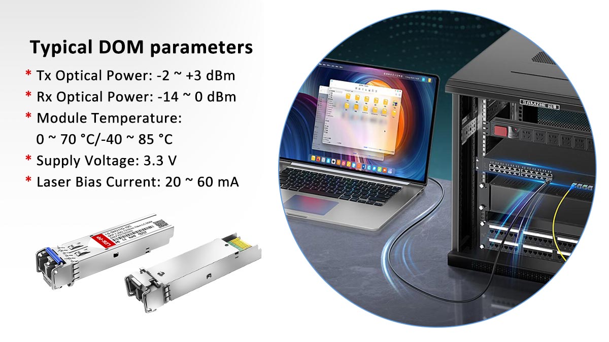
Parameter | Description |
|---|---|
TX Power | Optical output level transmitted by the module |
RX Power | Optical signal level received from the fiber |
Temperature | Operating temperature of the transceiver |
Voltage | Stability of the module’s power supply |
Among these metrics, RX optical power is often the most useful indicator when diagnosing fiber issues. If the received power is significantly lower than the expected range, it may indicate problems such as:
Contaminated fiber connectors blocking part of the optical signal
Excessive fiber distance or attenuation beyond the module’s supported range
Poor-quality or damaged connectors causing signal loss
Incorrect fiber type or mismatched optics
Regularly checking DOM values allows network engineers to detect optical degradation early and prevent unexpected link failures, especially in data center or enterprise fiber networks.
Tools Needed for Effective SFP Troubleshooting
Efficient SFP troubleshooting requires the right set of diagnostic tools. While many issues can be identified through switch commands and visual inspection, specialized tools help engineers quickly verify fiber cleanliness, optical signal levels, and hardware functionality.

SFP Diagnostics Tools:
Fiber inspection microscope
Used to examine the fiber connector end face for dust, oil, or scratches that can degrade optical signal quality.Fiber cleaning kit
Includes cleaning pens, lint-free wipes, and cleaning fluid to remove contamination from fiber connectors and adapters.Known good SFP module
A verified working transceiver that can be swapped into the device to determine whether the issue is caused by a faulty module.Optical power meter
Measures the actual optical signal strength transmitted through the fiber link, helping confirm whether power levels fall within the expected operating range.Loopback fiber cable
Used to connect the transmitter (Tx) and receiver (Rx) of the same port to verify whether the SFP module and switch port are functioning correctly.
Using the proper tools allows engineers to quickly isolate whether the problem originates from the fiber cable, the optical module, or the network device itself, significantly reducing troubleshooting time and minimizing network downtime.
Preventive Best Practices for SFP Reliability
While effective troubleshooting is important, preventing SFP-related issues in the first place is even more valuable for maintaining stable network operations. By following several preventive best practices, network administrators can significantly reduce the risk of link failures, optical signal degradation, and unexpected downtime.
Minimize SFP Failures Practices:

Always clean fiber connectors before installation
Fiber connectors should be inspected and cleaned prior to connection. Even small dust particles can cause optical signal loss or increased attenuation.Use vendor-approved or compatible modules
Deploy SFP modules that are certified or verified to work with the network equipment. Compatibility issues may cause modules to be rejected or operate unreliably.Monitor DOM metrics regularly
Regularly review Digital Optical Monitoring (DOM) data such as transmit power, receive power, and temperature to detect potential signal degradation early.Maintain proper airflow around switches
Ensure that switches and routers have adequate ventilation. Excessive heat can affect transceiver performance and shorten the lifespan of optical modules.
Implementing these preventive measures helps maintain stable optical connectivity, reduces troubleshooting frequency, and prevents unexpected network outages in enterprise or data center environments.
FAQs About SFP Troubleshooting
Below are answers to some of the most common questions engineers encounter when diagnosing SFP connectivity issues.
Q1. Why is my SFP module not detected?
An SFP module may not be detected due to compatibility restrictions, firmware limitations, or a faulty transceiver. Many enterprise switches from vendors such as Cisco, Juniper, or Brocade enforce compatibility checks to ensure that supported optics are used.
To troubleshoot this issue:
Verify the module in the device compatibility matrix
Test the port using a known working SFP module
Review system logs (for example using
show logging) to identify detection errors
Q2. Why is my SFP module marked as “Unsupported”?
An “Unsupported transceiver” message usually appears when the switch firmware does not recognize the SFP module. This can happen due to:
Vendor compatibility restrictions
Incorrect or missing EEPROM identification data in the module
Firmware or software version limitations on the switch
To resolve the issue, check the vendor compatibility list and review system logs to identify the specific reason for the rejection.
Q3. What causes SFP link flapping?
Link flapping occurs when a network interface repeatedly transitions between up and down states.
Common causes include:
Dirty or contaminated fiber connectors
Weak or unstable optical signals
Faulty fiber patch cables
Hardware defects in the SFP module
Cleaning the connectors and verifying optical power levels through DOM diagnostics often helps stabilize the link.
Q4. What should I do if the fiber link is intermittent?
If the connection works intermittently, start with the following checks:
Inspect and clean the fiber connector end faces.
Check optical transmit and receive power levels through DOM monitoring.
Perform a module swap test using a known working SFP module.
If the issue persists after these steps, collect diagnostic logs and contact the equipment vendor for further analysis.
Q5. Can third-party SFP modules work with enterprise switches?
Yes, many enterprise switches support compatible third-party SFP modules, which can provide a cost-effective alternative to original vendor optics. However, some vendors enforce compatibility checks that may generate warnings or prevent unsupported modules from operating.
Before deploying third-party optics in production environments, it is recommended to:
Verify compatibility with the specific switch model
Test modules in a controlled environment
Understand any potential impact on vendor support or warranty policies.
Conclusion: How to Diagnose and Resolve SFP Problems Efficiently
SFP troubleshooting becomes significantly easier when engineers follow a structured diagnostic workflow instead of randomly replacing components.
In most cases, common issues such as no link, module detection failure, or unstable connections can be resolved by systematically checking:
Physical installation of the SFP module
Fiber cleanliness and connector condition
Optical compatibility (fiber type, wavelength, and speed)
Digital Optical Monitoring (DOM) diagnostics
Following this step-by-step process allows network engineers to quickly isolate whether the problem originates from the transceiver, fiber cable, or switch configuration.
In addition, learning vendor-specific troubleshooting commands and continuously monitoring optical parameters—such as TX/RX power levels and temperature—helps prevent recurring failures and ensures stable, reliable fiber network performance in enterprise and data center environments.
For production networks, combining proper troubleshooting methods with preventive maintenance practices is the most effective way to reduce downtime and maintain long-term optical network reliability.
For network deployments requiring reliable optical connectivity, choosing high-quality SFP modules and compatible components is essential.
Explore professional networking components and optical solutions at LINK-PP Official Store, or contact our technical team for compatibility guidance and product specifications.


