

When engineers search for “SFP wavelength,” they are typically trying to answer a practical deployment question: Which optical wavelength should I use—850 nm, 1310 nm, or 1550 nm—and why does it matter? The answer directly affects fiber compatibility, transmission distance, link stability, and overall network reliability.
In optical transceivers, wavelength refers to the nominal center wavelength of the transmitter laser. That value determines whether the module is designed for multimode fiber (MMF) or single-mode fiber (SMF), how much attenuation the signal will experience, how dispersion behaves over distance, and whether optical amplification or DWDM systems are possible. Choosing the wrong wavelength can result in immediate link failure, unstable performance, or insufficient optical margin.
The three dominant SFP wavelength categories—850 nm, 1310 nm, and 1550 nm—are not interchangeable. Each corresponds to specific fiber types, reach classes, and application environments such as short-reach data center links, campus backbones, metropolitan aggregation, or long-haul transmission. Understanding their differences requires more than memorizing distance numbers; it involves evaluating link budget, dispersion characteristics, and interoperability constraints.
This guide provides a structured, engineering-level explanation of SFP wavelengths, including comparison tables, link-budget logic, deployment checklists, and common troubleshooting scenarios. Whether you are selecting modules for a new installation or diagnosing a wavelength mismatch, the goal is to provide technically accurate, decision-ready information aligned with real-world network design practices.
↪️ What Is SFP Wavelength?
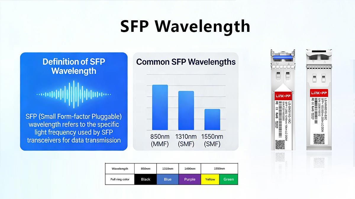
SFP wavelength refers to the nominal center wavelength of the laser transmitter inside a Small Form-factor Pluggable (SFP) optical transceiver. It defines the specific light spectrum—commonly 850 nm, 1310 nm, or 1550 nm—used to transmit data over optical fiber.
The selected wavelength determines fiber compatibility. 850 nm SFP modules are designed for multimode fiber (MMF), where modal dispersion limits transmission distance but enables cost-effective short-reach links. In contrast, 1310 nm and 1550 nm SFP modules are designed for single-mode fiber (SMF), which supports significantly longer distances due to lower attenuation and reduced dispersion effects.
Wavelength also directly correlates with reach classification. For example, 850 nm is typically used for short-reach (SR) applications within data centers, 1310 nm supports medium-reach (LR) campus or metro links, and 1550 nm is commonly deployed for extended-reach (ER/ZR) or long-haul transmission environments.
↪️ Why Wavelength Matters in Optical Transceivers
Wavelength is not just a labeling parameter—it directly determines how light propagates through fiber, how far it can travel, and how stable the link remains under real traffic conditions. In practical network design, wavelength affects attenuation, dispersion, link margin, bit error rate (BER), and even whether optical amplification is possible.
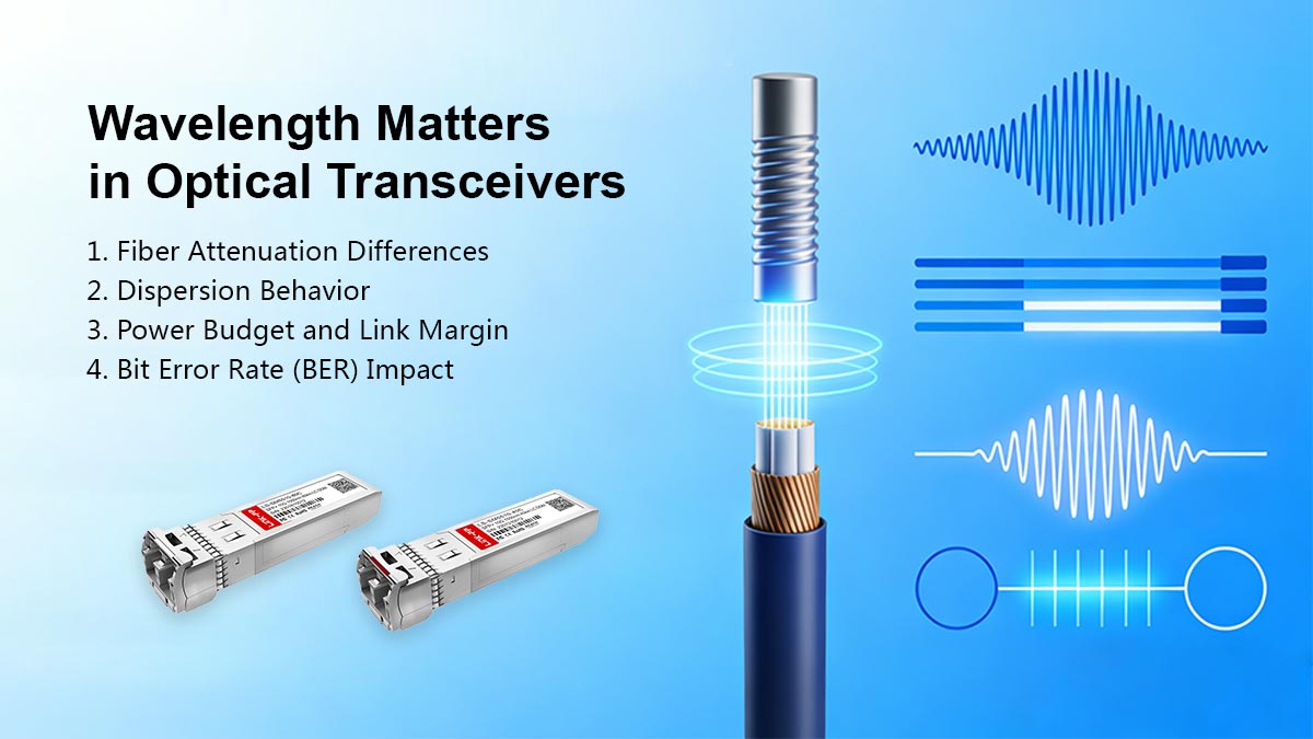
1. Fiber Attenuation Differences
Optical fiber does not attenuate all wavelengths equally. Signal loss (measured in dB/km) varies depending on the transmission window:
MMF 850nm: Higher attenuation, typically around 2–3 dB/km in multimode fiber.
SMF 1310nm: Lower attenuation, typically ~0.35 dB/km in single-mode fiber.
SMF 1550nm: Lowest attenuation window, typically ~0.20–0.25 dB/km in single-mode fiber.
Because 1550 nm experiences the lowest intrinsic fiber loss, it supports the longest transmission distances under comparable power conditions.
2. Dispersion Behavior
Dispersion causes optical pulses to spread as they travel, limiting usable bandwidth over distance.
Modal dispersion primarily affects 850 nm multimode systems, where multiple propagation paths cause pulse broadening. This is why 850 nm links are distance-limited in data center environments.
Chromatic dispersion becomes more relevant in single-mode fiber at 1310 nm and 1550 nm.
Around 1310 nm, chromatic dispersion is near zero in standard single-mode fiber.
At 1550 nm, chromatic dispersion is higher but manageable with proper system design.
Dispersion directly impacts maximum achievable reach and high-speed performance (e.g., 10G, 25G, or higher).
3. Power Budget and Link Margin
Wavelength influences link feasibility through the optical power budget. The core engineering relationship is:
Available Margin=Tx(min)−Total Link Loss−Rx(min)Since attenuation differs by wavelength, the same transmitter power can produce very different maximum distances. For example:
850 nm systems consume link budget quickly due to higher attenuation and modal dispersion.
1550 nm systems preserve more optical margin over long spans.
A mismatch between wavelength and required distance often results in insufficient margin or unstable operation.
4. Bit Error Rate (BER) Impact
As attenuation and dispersion increase, signal integrity degrades. This leads to:
Reduced optical signal-to-noise ratio (OSNR)
Eye diagram closure
Increased bit error rate (BER)
While forward error correction (FEC) can compensate for minor impairments, wavelength selection remains fundamental to achieving acceptable BER performance without excessive correction overhead.
5. Optical Amplifier Compatibility (EDFA at 1550 nm)
One of the major advantages of 1550 nm transmission is compatibility with Erbium-Doped Fiber Amplifiers (EDFA). EDFAs operate efficiently in the 1550 nm window, enabling:
Long-haul transmission
DWDM systems
Span extension without electrical regeneration
Amplification is not practical at 850 nm and is uncommon at 1310 nm, making 1550 nm the preferred wavelength for metro and long-distance backbone networks.
Engineering Summary
Wavelength determines how far a signal travels, how cleanly it arrives, and whether amplification is possible. Attenuation, dispersion, power budget, BER performance, and amplifier compatibility are all wavelength-dependent factors that must be evaluated during optical transceiver selection.
↪️ 850nm SFP (Multimode) Applications
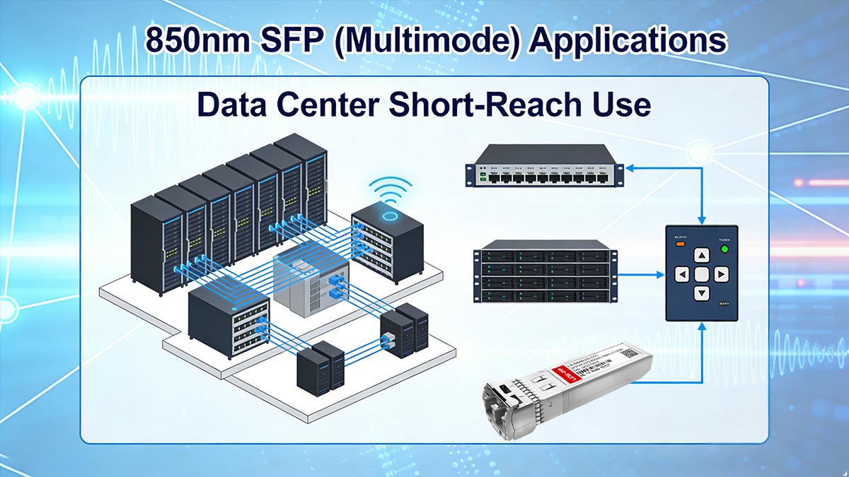
The 850nm multimode SFP transceiver is primarily designed for short-reach communication over multimode fiber (MMF). It is widely deployed in data centers and enterprise networks where link distances are limited but high port density and cost efficiency are critical.
VCSEL Technology
Most 850 nm SFP modules use VCSEL (Vertical-Cavity Surface-Emitting Laser) technology. VCSELs offer:
Low manufacturing cost
High modulation efficiency
Low power consumption
Reliable operation at short distances
Because VCSEL emission couples efficiently into multimode fiber cores (50/125 µm or 62.5/125 µm), 850 nm has become the dominant wavelength for short-reach Ethernet standards such as those defined under IEEE 802.3z and IEEE 802.3ae (SR variants).
OM3 / OM4 Fiber Compatibility
850 nm SFP modules are optimized for laser-optimized multimode fibers:
OM3 (typically supports 10G up to 300 m)
OM4 (typically supports 10G up to 400 m)
These fibers are engineered with improved modal bandwidth to reduce differential mode delay compared to older OM1/OM2 fibers. Performance strongly depends on fiber quality and installation conditions.
Typical Reach
Reach varies by Ethernet speed and fiber grade:
1G (1000BASE-SX): up to ~550 m on high-grade MMF
10G (10GBASE-SR):
~300 m on OM3
~400 m on OM4
Higher speeds (25G/40G SR variants): typically shorter distances
Modal dispersion is the primary limiting factor, not just attenuation.
Data Center Short-Reach Use
850 nm SFP multimode modules are ideal for:
Top-of-rack (ToR) to aggregation switch links
Server-to-switch interconnects
High-density data center fabrics
Short intra-building backbone connections
They offer compact form factors and support high port counts in switch environments.
Cost Advantage
Compared to single-mode 1310 nm or 1550 nm solutions:
Transceiver cost is generally lower
Multimode fiber patching is often less expensive in short runs
VCSEL production is more cost-efficient than DFB laser manufacturing
This makes 850 nm an economical solution for short-distance deployments.
Limitations
Despite its advantages, 850 nm SFP multimode has constraints:
Limited maximum distance due to modal dispersion
Not suitable for campus or metro links
No compatibility with optical amplifiers
Higher attenuation compared to single-mode transmission windows
For distances beyond a few hundred meters, 1310 nm or 1550 nm single-mode solutions are typically required.
Engineering conclusion:
850nm SFP multimode modules are optimized for short-distance, high-density, cost-sensitive environments—particularly modern data centers—but are not designed for long-reach or backbone transmission.
↪️ 1310nm SFP (Single-Mode) Applications
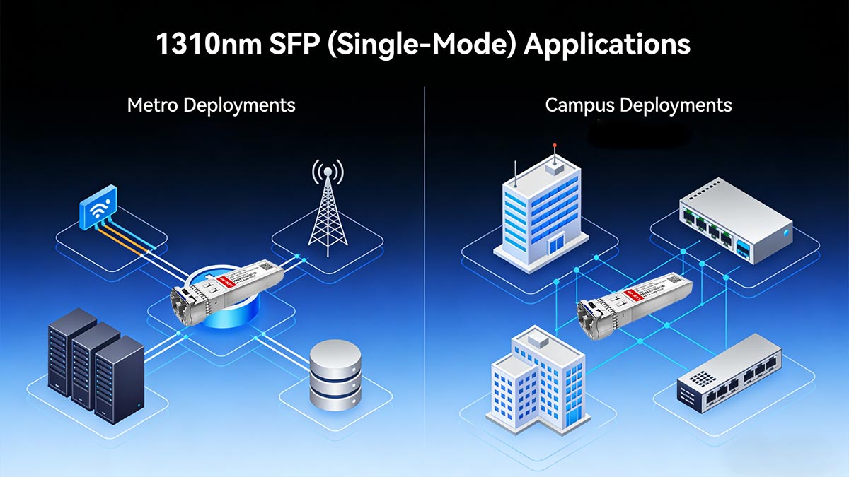
The 1310nm SFP singlemode transceiver is designed for transmission over single-mode fiber (SMF) and is widely used in campus, enterprise backbone, and metro-access networks. It offers a balanced combination of moderate attenuation, minimal modal dispersion, and practical reach for medium-distance deployments.
Single-Mode Fiber (SMF) Transmission
1310 nm SFP modules operate over standard 9/125 µm single-mode fiber. Unlike multimode systems, single-mode fiber supports only one propagation mode, which eliminates modal dispersion and enables significantly longer transmission distances.
Common Ethernet implementations at 1310 nm are defined under IEEE 802.3z (1000BASE-LX) and IEEE 802.3ae (10GBASE-LR).
Typical Reach: 10 km to 20 km
1310 nm SFP singlemode modules are typically specified for:
10 km (standard LR class)
20 km (extended reach variants, depending on optical budget)
Actual reach depends on transmitter output power, receiver sensitivity, total link loss, and connector/splice quality. With proper link budgeting, stable performance at these distances is achievable without optical amplification.
Metro and Campus Deployments
1310 nm SFP modules are commonly used for:
Inter-building campus backbone connections
Enterprise aggregation layers
Metro access rings
ISP edge-to-access node links
They provide sufficient distance capability without the complexity or cost of long-haul 1550 nm systems.
Lower Modal Dispersion
Because transmission occurs in single-mode fiber, modal dispersion is effectively eliminated. Additionally, chromatic dispersion is near its zero-dispersion point around 1310 nm in standard SMF, which helps maintain signal integrity over medium distances.
This dispersion characteristic makes 1310 nm particularly stable for 1G and 10G Ethernet speeds without requiring advanced dispersion compensation.
Moderate Attenuation
Fiber attenuation at 1310 nm is typically around 0.35 dB/km in standard single-mode fiber. While higher than the 1550 nm window, it remains low enough to support multi-kilometer links with adequate optical margin.
Because of this balance between attenuation and dispersion performance, 1310 nm is often considered the default choice for medium-distance single-mode deployments.
Engineering conclusion:
1310nm SFP singlemode modules provide a practical and reliable solution for 10–20 km transmission in campus and metro environments, offering low dispersion, manageable attenuation, and straightforward link budgeting without the need for optical amplification.
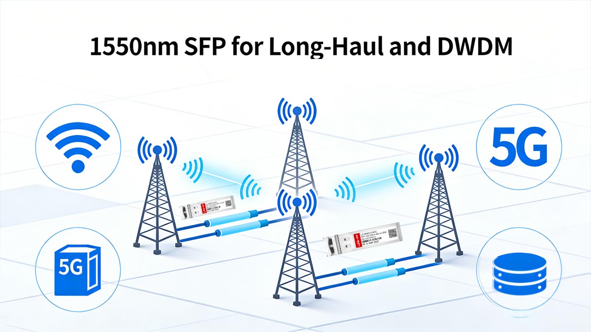
↪️ 1550nm SFP for Long-Haul and DWDM
The 1550nm SFP long distance transceiver is optimized for extended-reach applications over single-mode fiber (SMF), where low attenuation and compatibility with optical amplification are essential. It is widely deployed in metropolitan, long-haul, and DWDM networks that require maximum distance and high channel density.
Lowest Fiber Attenuation
1550 nm operates in the low-loss window of SMF, with typical attenuation around 0.20–0.25 dB/km, significantly lower than 850 nm multimode or 1310 nm single-mode systems. This property allows optical signals to travel longer distances before requiring amplification or regeneration.
Longest Reach
Because of reduced attenuation and manageable dispersion, 1550 nm SFP modules support the longest practical single-mode links without intermediate electronics. Typical applications include:
Long-haul backbone links spanning tens to hundreds of kilometers
Metro ring aggregation between distant sites
Submarine and inter-city networks (when paired with EDFAs)
Reach is limited primarily by transmitter power, receiver sensitivity, and accumulated link loss from splices, connectors, and fiber attenuation.
EDFA Compatibility
One of the major advantages of the 1550 nm wavelength is compatibility with Erbium-Doped Fiber Amplifiers (EDFAs). EDFAs efficiently amplify optical signals in the 1550 nm window without converting them to electrical signals, enabling:
Extended long-haul transmission
Dense Wavelength Division Multiplexing (DWDM) over a single fiber
Reduced need for intermediate repeaters or regeneration points
EDFA compatibility makes 1550 nm ideal for high-capacity backbone and metro networks.
DWDM Channel Grid Concept
In Dense Wavelength Division Multiplexing (DWDM) systems, multiple channels are transmitted simultaneously on a single fiber using precise 1550 nm sub-wavelengths. Key considerations include:
Channel spacing (e.g., 50 GHz, 100 GHz)
Wavelength stability and tolerance
Alignment with transceiver nominal wavelength
1550 nm SFP modules can be used in DWDM pairs when the nominal wavelength aligns with the defined channel grid.
Higher Cost Optics
1550 nm SFPs generally cost more than 850 nm multimode or 1310 nm single-mode modules due to:
Higher-precision lasers
Temperature stabilization requirements
Optical amplifier integration capability
Despite higher cost, they provide essential long-distance performance and DWDM compatibility for enterprise, metro, and carrier-grade networks.
Engineering conclusion:
1550nm SFP long-distance modules are the preferred choice for applications requiring minimal attenuation, long-reach connectivity, and EDFA/DWDM compatibility. While more expensive, their extended reach and amplifier support make them essential for high-capacity backbone and metro deployments.
↪️ How to Choose the Correct SFP Wavelength
Selecting the appropriate SFP wavelength is critical for reliable optical link performance. A systematic decision process ensures compatibility, sufficient optical margin, and stable data transmission.
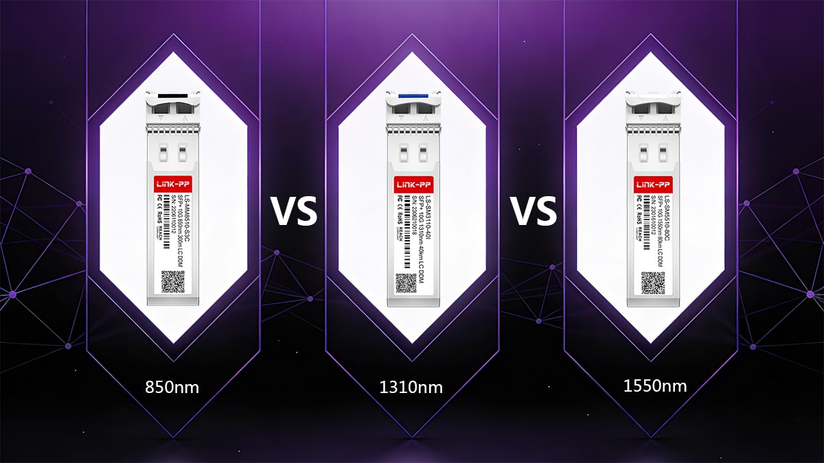
850nm vs. 1310nm vs. 1550nm (Comparison Table)
The following table provides a concise engineering comparison of the three most common SFP wavelengths, highlighting fiber compatibility, typical reach, attenuation, dispersion behavior, and typical deployment scenarios.
Parameter | 850nm | ||
|---|---|---|---|
Fiber Type | Multimode Fiber (OM3 / OM4) | Single-Mode Fiber (SMF) | Single-Mode Fiber (SMF) |
Typical Reach | 100–400 m (SR) | 10–20 km (LR) | 40–120+ km (ER/ZR with EDFA) |
Attenuation (dB/km) | ~2–3 dB/km | ~0.35 dB/km | ~0.20–0.25 dB/km |
Dispersion Type | Modal dispersion dominant | Near-zero chromatic dispersion | Chromatic dispersion increases with distance |
Use Case | Data center short-reach links | Campus or metro medium-reach | Long-haul, DWDM, backbone networks |
Amplifier Compatibility | No | Limited / uncommon | Compatible with EDFA |
Notes:
850nm is cost-effective for short distances but limited by modal dispersion.
1310nm is standard for medium-distance single-mode applications with stable performance and moderate attenuation.
1550nm enables the longest distances and DWDM channelization, but optics are higher cost.
This comparison table serves as a practical reference for engineers evaluating SFP wavelength selection based on fiber type, distance, and network application.
1. Identify Fiber Type
Determine whether the link uses multimode fiber (MMF) or single-mode fiber (SMF).
850 nm is typically used for MMF, while 1310 nm and 1550 nm are designed for SMF.
Mismatched wavelength and fiber type is the most common cause of link failure.
2. Measure Link Distance
Calculate the physical distance between transmitter and receiver.
Include patch panels, connectors, and any fiber routing changes.
Ensure distance falls within the maximum reach for the chosen wavelength (e.g., 850 nm up to 400 m on OM4, 1310 nm up to 20 km, 1550 nm up to 120+ km with amplification).
3. Calculate Link Loss
Estimate total optical loss using:
Total Loss (dB) = Fiber Loss + Connector Loss + Splice LossCompare total link loss against the transceiver’s Tx output power and receiver sensitivity to ensure sufficient margin.
Link Budget Calculation Example
A link budget determines whether an optical connection can operate reliably over a given distance. The fundamental formula for link margin is:
Available Margin (dB) = Tx(min)−Total Link Loss−Rx(min)Where:
Tx(min) = Minimum transmitter output power (dBm)
Total Link Loss = Sum of fiber, connector, and splice losses (dB)
Rx(min) = Receiver sensitivity (minimum detectable power, dBm)
Example Calculation
Assume the following 10G-SR link over OM4 multimode fiber:
Parameter | Value |
|---|---|
Tx(min) | -3 dBm |
Fiber Loss | 0.5 dB/km × 150 m = 0.075 dB |
Connector Loss | 4 connectors × 0.5 dB = 2.0 dB |
Splice Loss | 2 splices × 0.1 dB = 0.2 dB |
Rx(min) | -11 dBm |
Step 1: Calculate Total Link Loss
Total Link Loss = 0.075+2.0+0.2=2.275 dBStep 2: Calculate Available Margin
Available Margin=−3−2.275−(−11)=5.725 dBInterpretation
The available margin of 5.7 dB indicates the link has sufficient optical budget for reliable operation.
A margin > 3 dB is generally considered safe for typical short-reach 850 nm SFP multimode links.
If margin falls below the recommended level, options include shorter fiber, better connectors, higher-power SFP, or using a lower-loss fiber type.
4. Confirm Receiver Sensitivity
Verify that the receiver at the far end can detect the chosen wavelength with adequate power margin.
Ensure the power level remains within the dynamic range specified in the transceiver datasheet to avoid errors or link instability.
5. Verify Wavelength Match Both Ends
Confirm that transmitter and receiver wavelengths are compatible:
For standard SR/LR links, both ends use identical nominal wavelength.
For BiDi SFPs, Tx and Rx wavelengths must be properly paired (e.g., 1310 nm TX / 1550 nm RX on one side, reversed on the other).
Double-check EEPROM coding and manufacturer compatibility lists to prevent host rejection or err-disabled states.
Conclusion:
By following this step-by-step process—fiber type identification, distance measurement, link loss calculation, receiver sensitivity verification, and wavelength matching—engineers can confidently select the correct SFP wavelength and minimize deployment errors.
↪️ Common SFP Wavelength Mistakes and Troubleshooting
Selecting the correct SFP wavelength is critical, but engineers frequently encounter operational issues when links are misconfigured. Understanding common mistakes and their symptoms can prevent downtime and ensure stable network performance.
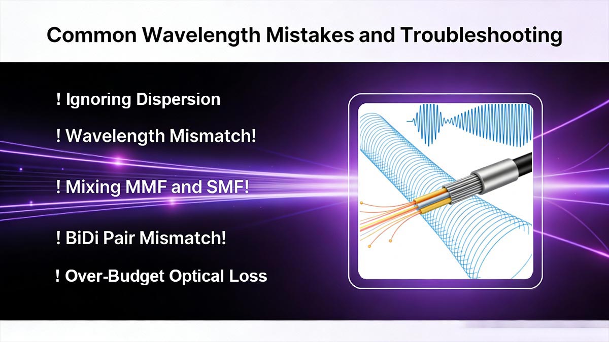
1. Wavelength Mismatch
Issue: Transmitter and receiver operate at different nominal wavelengths (e.g., 1310 nm TX to 1550 nm RX).
Symptom: No link establishment or intermittent connectivity.
Troubleshooting: Verify the nominal wavelength on both SFPs and ensure they match the fiber type and application.
2. Mixing MMF and SMF
Issue: An 850 nm multimode SFP is connected to single-mode fiber, or 1310/1550 nm single-mode SFP is used on multimode fiber.
Symptom: Link flaps, high bit error rate, or complete failure.
Troubleshooting: Confirm fiber type and replace the SFP with a module compatible with the fiber.
3. BiDi Pair Mismatch
Issue: Bidirectional (BiDi) SFP pairs have TX/RX wavelengths reversed.
Symptom: Err-disabled ports or no DOM data.
Troubleshooting: Swap the SFPs at one end to align TX and RX wavelengths correctly. Check EEPROM coding for proper BiDi pairing.
BiDi SFP Wavelength Pairing Explained
BiDi (Bidirectional) SFP modules transmit and receive signals on a single fiber using two different wavelengths. Common pairs include 1310 nm TX / 1550 nm RX and 1550 nm TX / 1310 nm RX, allowing duplex communication over one fiber instead of two.
Why Wavelengths Must Be Reversed
In a BiDi link, the transmitter on one end must match the receiver wavelength on the other end.
Example:
Site A: 1310 nm TX → 1550 nm RX
Site B: 1550 nm TX → 1310 nm RX
Reversing the pair at either end prevents the transmitted signal from reaching the correct receiver, resulting in no link or err-disabled ports.
Common Deployment Errors
Incorrect BiDi pairing: Installing two modules with the same TX wavelength on both ends.
Symptom: Link failure, no DOM readings.
Using BiDi on the wrong fiber type: MMF BiDi on SMF or vice versa.
Symptom: Intermittent connectivity or high BER.
EEPROM mismatch: Non-certified third-party BiDi modules may have incorrect vendor coding.
Symptom: Device rejection or err-disabled interface.
Engineering takeaway:
Always confirm that BiDi SFPs are installed as proper TX/RX complementary pairs and matched to the correct fiber type. Proper pairing ensures reliable single-fiber duplex operation and avoids costly troubleshooting.
4. Ignoring Dispersion
Issue: Long single-mode links exceed the dispersion budget for the chosen wavelength and data rate.
Symptom: Increased bit error rate or signal degradation over distance.
Troubleshooting: Calculate chromatic dispersion for 1310/1550 nm links. Use dispersion-compensated fiber or select a lower-speed transceiver if necessary.
5. Over-Budget Optical Loss
Issue: Total link loss exceeds the transceiver’s optical budget.
Symptom: Intermittent link failures, low optical margin, or unstable BER.
Troubleshooting: Measure connector and splice losses, reduce fiber path length if possible, or choose higher-power SFP modules.
Summary:
Proactive verification of wavelength, fiber type, link loss, and BiDi alignment prevents most SFP-related issues.
↪️ SFP Wavelength FAQ
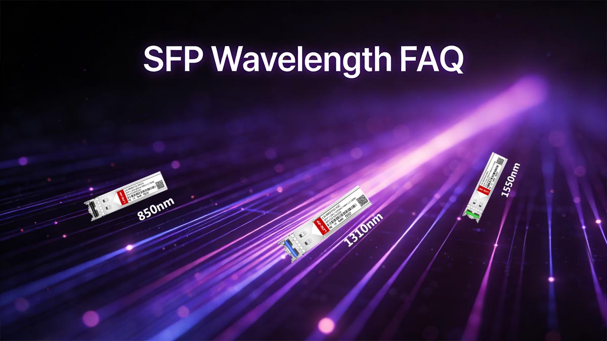
Q1: Can I use 850nm SFP on single-mode fiber?
No. 850 nm modules are designed for multimode fiber. Using them on single-mode fiber may cause high attenuation, unstable links, or complete failure.
Q2: What happens if wavelengths do not match?
The link may fail to establish or experience erratic performance. TX and RX wavelengths must correspond for proper optical reception.
Q3: Is 1550nm always better than 1310nm?
Not always. 1550 nm offers longer reach and EDFA/DWDM compatibility, but 1310 nm is sufficient for medium-distance campus or metro links with lower cost.
Q4: How do I check SFP wavelength in CLI?
Use commands like show interface transceiver or show inventory to read module type, nominal wavelength, and DOM parameters directly from the SFP.
Q5: Can I mix BiDi SFPs with standard SFPs?
No. BiDi SFPs require complementary TX/RX pairing on a single fiber. Mixing with standard SFPs can prevent link establishment.
Q6: How precise is the wavelength tolerance?
Typically ±3–10 nm. Tolerance ensures alignment with fiber and, in DWDM systems, correct channel placement.
Q7: What is the role of DOM in wavelength verification?
DOM monitors real-time Tx/Rx power, temperature, and optical margin, helping verify correct wavelength operation and detect potential link issues early.
↪️ SFP Wavelength Deployment Validation Checklist
Ensuring reliable SFP operation requires a systematic validation process. The following checklist helps engineers confirm that wavelength selection and link setup meet technical requirements:
✔ Match Fiber Type
Ensure that the SFP wavelength aligns with the installed fiber: 850 nm for MMF, 1310 nm or 1550 nm for SMF. Mismatched fiber can lead to link failure or degraded performance.✔ Match Wavelength Both Ends
Verify that the transmitter wavelength on one end corresponds to the receiver wavelength on the other. For BiDi SFPs, confirm that TX and RX wavelengths are complementary.✔ Confirm Power Budget
Calculate total link loss (fiber, connectors, splices) and ensure it does not exceed the transceiver’s optical budget. Maintain sufficient margin to account for environmental variations.✔ Verify DOM Readings
Use Digital Optical Monitoring (DOM) to check real-time transmit/receive power, optical margin, and temperature. DOM verification helps detect misaligned wavelengths or degraded fiber.✔ Maintain Firmware Consistency
Ensure that switch or router firmware is compatible with the SFP vendor and module type. Inconsistent firmware can cause err-disabled interfaces or module rejection.
Engineering summary:
Following this checklist minimizes wavelength-related deployment errors, ensures optical link reliability, and supports operational stability across both short- and long-reach networks.
Choosing the correct SFP wavelength—whether 850 nm for multimode short-reach, 1310 nm for medium-reach single-mode, or 1550 nm for long-haul and DWDM—is critical for reliable optical network performance. Understanding attenuation, dispersion, link budget, and DOM monitoring ensures that your transceivers operate optimally within their specified parameters.
Following structured deployment and validation processes, including fiber type verification, wavelength matching, power budget calculation, and firmware consistency checks, minimizes errors and maximizes link stability across both data center and long-haul networks.
For engineers seeking high-quality, standards-compliant SFP modules with precise wavelength specifications and full interoperability, explore the LINK-PP Official Store for a wide range of 850 nm, 1310 nm, and 1550 nm SFP transceivers, including modules with validated DOM support and guaranteed EEAT-compliant documentation.
Standards and Specifications
SFP transceivers operate according to well-defined industry standards, which ensure interoperability, predictable performance, and reliable monitoring. Key references include IEEE 802.3z, IEEE 802.3ae, and SFF-8472.
Wavelength Tolerance
Each SFP module has a nominal wavelength (e.g., 850 nm, 1310 nm, 1550 nm) with a specified tolerance, typically ±3–10 nm depending on the standard and data rate.
Tolerance ensures that the optical signal aligns with the fiber’s low-loss window and, in DWDM applications, with the correct channel grid.
Exceeding the tolerance can lead to reduced link margin, increased BER, or complete link failure.
DOM (Digital Optical Monitoring)
DOM, defined in SFF-8472, provides real-time monitoring of transceiver parameters:
Transmit power (Tx)
Receive power (Rx)
Module temperature
Supply voltage
Laser bias current
Engineers use DOM data to validate optical performance, confirm wavelength alignment, and detect potential degradation before it affects link reliability.
Engineering summary:
Adhering to IEEE and SFF standards ensures that SFP modules meet wavelength specifications and provide reliable DOM monitoring, enabling predictable performance, easier troubleshooting, and compatibility across devices from different vendors.


