

Selecting the correct SFP module is not simply a matter of matching connectors. In modern Ethernet networks, choosing the wrong transceiver can result in link failures, speed mismatches, compatibility errors, or unexpected distance limitations. For network engineers, system integrators, and IT buyers, understanding how to choose the right SFP module for compatibility, speed, and distance is essential to ensuring stable and scalable infrastructure.
SFP (Small Form-factor Pluggable) modules are hot-swappable optical or copper transceivers used in switches, routers, firewalls, and network interface cards. Defined under the Small Form Factor Committee specifications and widely deployed in equipment compliant with IEEE Ethernet standards, SFP modules provide flexible connectivity across access, aggregation, and data center layers.
However, not all SFP modules are interchangeable. Differences in:
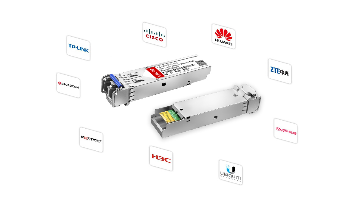
Vendor compatibility and MSA coding
Data rate (1G vs. 10G vs. 25G)
Fiber type (single-mode vs. multi-mode)
Optical wavelength (850nm, 1310nm, 1550nm)
Transmission distance (300m to 80km+)
Operating temperature (commercial vs. industrial)
can directly determine whether a link functions correctly.
This guide provides a practical, engineering-focused framework for selecting the appropriate SFP module based on measurable network parameters rather than assumptions. It is written for professionals who need accurate technical guidance—whether validating an enterprise switch deployment, upgrading to 10G or 25G infrastructure, or selecting modules for industrial Ethernet environments.
By the end of this article, you will understand:
How to verify SFP module compatibility with your switch or router
How to determine whether you need SFP, SFP+, or SFP28
How to match fiber type and wavelength correctly
How to calculate suitable transmission distance
When industrial temperature or DOM monitoring is required
The goal is straightforward: eliminate guesswork and prevent costly deployment mistakes by applying a structured, standards-based selection method.
Let’s begin with the most critical factor—compatibility.
▶ Step 1 — Verify SFP Module Compatibility (MSA and Vendor Coding)
Compatibility is the single most common cause of SFP deployment failures. Before considering speed, distance, or wavelength, you must confirm that the module will be recognized and supported by your switch or router.
In most enterprise networks, incompatibility does not result in physical damage—but it does result in ports remaining down, error logs, or warning messages such as “unsupported transceiver.” Understanding the standards and vendor policies behind SFP compatibility eliminates this risk.
What Is MSA (Multi-Source Agreement)?
MSA stands for Multi-Source Agreement. It is an industry agreement that defines the mechanical dimensions, electrical interface, and optical specifications of pluggable transceivers.
The original SFP form factor specification was defined by the Small Form Factor Committee under the SFF-8472 and related documents. Ethernet signaling standards, such as 1000BASE-SX, 10GBASE-LR, and 25GBASE-SR, are defined by the IEEE (for example, IEEE 802.3z, 802.3ae, and 802.3by).
What MSA guarantees:
Standardized physical dimensions (the module fits the port)
Defined electrical interface
Standard optical performance ranges
What MSA does NOT guarantee:
Automatic vendor recognition
Freedom from firmware restrictions
Cross-brand acceptance in all switches
In practical terms, MSA compliance ensures hardware-level interoperability, but it does not override vendor firmware controls.
Vendor-Coded vs. Generic SFP Modules
Most enterprise switch vendors implement firmware-based transceiver validation. When an SFP module is inserted, the switch reads EEPROM data stored inside the module. This data includes:
Vendor name
Part number
Serial number
Compliance codes
If the firmware detects an unsupported vendor ID, the device may:
Disable the port
Display a warning
Log a non-supported transceiver error
Vendor-coded SFP modules contain EEPROM data programmed specifically for a particular brand (e.g., Cisco-coded, Juniper-coded, etc.).
Generic (uncoded or universal) SFP modules follow MSA standards but may not contain brand-specific EEPROM programming.
From a performance standpoint, there is no inherent optical difference between a properly manufactured generic module and a vendor-coded module. The distinction lies in firmware acceptance policy.
For production networks, always verify whether your switch enforces vendor lock-in policies before purchasing modules.
Can You Mix and Match SFP Modules?
Yes—with conditions.
You can mix SFP modules from different manufacturers if all of the following are true:
Both ends comply with the same Ethernet standard (e.g., 10GBASE-LR to 10GBASE-LR).
Wavelength and distance specifications match.
Both switches accept the installed module (firmware recognition).
Optical power levels are within compatible ranges.
For example:
10GBASE-SR ↔ 10GBASE-SR over multimode fiber: valid.
10GBASE-LR ↔ 10GBASE-LR over single-mode fiber: valid.
10GBASE-SR ↔ 10GBASE-LR: not compatible.
Mixing brands is common in modern data centers, provided that modules are correctly coded and meet IEEE optical specifications.
How to Check Switch Compatibility
Before purchasing SFP modules, follow this structured validation process:
1. Check the Switch Hardware Specification
Review the official datasheet to confirm:
Supported port speed (1G / 10G / 25G)
Supported form factor (SFP / SFP+ / SFP28)
Backward compatibility (if supported)
Important:
A 1G SFP port cannot operate a 10G SFP+ module.
Some 10G SFP+ ports support 1G fallback—but not all.
2. Review the Vendor’s Transceiver Compatibility Matrix
Most major vendors publish a compatibility list that specifies approved module part numbers.
This is especially important for:
Enterprise campus switches
Carrier-grade routers
Industrial Ethernet switches
3. Confirm Firmware Version
Older firmware versions may not recognize newer module revisions. Always verify firmware compatibility.
4. Verify EEPROM Coding Requirements
If the switch enforces vendor-coded modules, ensure your supplier programs EEPROM data accordingly.
Compatibility Checklist (Quick Reference)
Before proceeding to speed or distance selection, confirm:
✔ Correct form factor (SFP / SFP+ / SFP28)
✔ Supported port speed
✔ Vendor acceptance policy
✔ Matching Ethernet standard
✔ Correct firmware version
Once compatibility is confirmed, the next critical factor is selecting the correct data rate, which directly determines whether your link operates at 1G, 10G, or 25G.
Let’s move to Step 2 — identifying the required speed.
▶ Step 2 — Identify Required SFP Data Rate (1G vs. 10G vs. 25G)
After confirming compatibility, the next decision is speed. Selecting the wrong data rate will either prevent the link from coming up or limit network performance.
SFP modules are available in multiple generations, each designed for a specific Ethernet signaling standard defined by the IEEE. The most common in enterprise and data center environments are:
1G (1000BASE-X)
10G (10GBASE-X)
25G (25GBASE-X)
Speed selection should be based on switch port capability, network architecture, and bandwidth requirements—not simply future-proof assumptions.
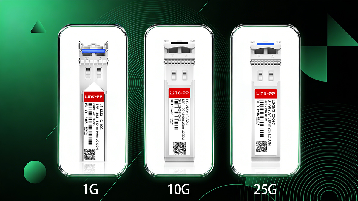
SFP (1G) vs. SFP+ (10G) vs. SFP28 (25G)
Although these modules share similar physical dimensions, they are not electrically identical and are not universally interchangeable.
Feature | |||
|---|---|---|---|
Typical Ethernet Standard | 1000BASE-SX/LX | 10GBASE-SR/LR/ER | 25GBASE-SR/LR |
Line Rate | 1.25 Gbps | 10.3125 Gbps | 25.78125 Gbps |
Typical Use Case | Access layer | Aggregation / Data center | High-density data center |
Backward Compatibility | Native 1G only | Some ports support 1G fallback | Rarely supports 10G fallback |
Power Consumption | Low | Moderate | Higher than SFP+ |
Common Deployment | Enterprise LAN | Server uplinks | Leaf-spine architectures |
Important technical note:
Although SFP, SFP+, and SFP28 modules share similar form factors, the electrical interface and signaling rates are different. A 1G SFP module cannot operate in a pure 10G-only port, and a 25G SFP28 module requires a 25G-capable port.
What Is the Difference Between 1G and 10G SFP?
The primary differences between 1G SFP and 10G SFP+ modules are:
1. Signaling Speed
This is a tenfold bandwidth increase.
2. Electrical Interface
SFP+ removes certain signal conditioning components from the module and shifts them to the host board. This allows higher speeds but requires a port specifically designed for 10G operation.
3. Application Layer
Typical deployment differences:
1G SFP: user access ports, legacy backbone links.
10G SFP+: server uplinks, switch aggregation, virtualization environments.
4. Port Compatibility
Critical rule:
A 1G SFP cannot operate in a 10G-only SFP+ port.
Some 10G SFP+ ports support 1G SFP modules, but this depends on switch design.
Always verify the hardware specification before mixing speeds.
What Is the Difference Between 10G and 25G SFP?
The difference between SFP+ (10G) and SFP28 (25G) is not merely speed scaling.
1. Line Rate
10G SFP+: 10.3125 Gbps
25G SFP28: 25.78125 Gbps
25G delivers 2.5× the bandwidth of 10G per lane.
2. Network Efficiency
25G Ethernet improves cost-per-bit efficiency in modern data centers. Instead of aggregating multiple 10G links, a single 25G link provides higher throughput with lower cable count.
3. Signal Integrity Requirements
25G operation requires tighter signal integrity and lower jitter tolerance. As a result:
25G ports are explicitly designed for SFP28 modules.
10G SFP+ modules typically do not operate in 25G-only ports unless specifically supported.
4. Deployment Context
10G: common in enterprise networks.
25G: common in hyperscale and high-density leaf-spine architectures.
How to Tell If an SFP Is 1G or 10G
You can determine the speed rating of an SFP module using the following methods:
1. Check the Label
Module labels usually include the Ethernet standard, such as:
1000BASE-SX → 1G
10GBASE-LR → 10G
25GBASE-SR → 25G
2. Check the SFP Datasheet
Look for:
Nominal bit rate
Ethernet compliance codes
Optical interface type
3. Read via CLI Command
Most managed switches allow you to query module information via CLI:
Example (varies by vendor):
show interfaces transceiver detailThe output typically lists:
Supported speed
Vendor name
Wavelength
DOM data (if supported)
4. Check the Port Type
If the port is labeled:
SFP → usually 1G
SFP+ → typically 10G
SFP28 → 25G capable
However, labeling conventions vary, so always confirm in the official hardware specification.
Is SFP Faster Than RJ45?
This question requires clarification because SFP is a form factor, while RJ45 is a connector type.
RJ45 typically refers to copper Ethernet connections such as:
1000BASE-T (1G)
10GBASE-T (10G)
SFP modules can be:
Optical (fiber-based)
Copper (RJ45 SFP modules)
Speed comparison depends on the specific standard:
1G SFP (fiber) = 1G RJ45 (copper)
10G SFP+ (fiber) = 10GBASE-T (RJ45 copper)
However, optical SFP+ often offers:
Lower latency
Lower power consumption
Longer distance capability
Copper 10GBASE-T typically consumes more power and is limited to 100 meters over Cat6A or better.
Therefore, SFP is not inherently faster than RJ45—the speed depends on the underlying Ethernet standard.
SFP Module Speed Selection Summary
Before proceeding to fiber and wavelength selection, confirm:
✔ Switch port maximum supported speed
✔ Required uplink bandwidth
✔ Future scalability requirements
✔ Backward compatibility needs
✔ Power and density considerations
Once speed is determined, the next step is selecting the correct fiber type—single-mode or multi-mode—which directly impacts distance and wavelength selection.
Let’s move to Step 3 — matching the fiber type.
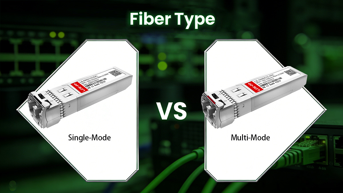
▶ Step 3 — Match the Fiber Type (Single-Mode vs. Multi-Mode)
After confirming compatibility and speed, the next critical factor in SFP module selection is fiber type. Choosing the wrong fiber type can prevent a link from establishing or significantly reduce the transmission distance. SFP modules are generally designed for either single-mode (SMF) or multi-mode fiber (MMF), and each type has specific wavelength and distance characteristics.
How to Tell If an SFP Is SM or MM
Identifying whether an SFP module is single-mode or multi-mode can be done in several ways:
Check the Label/Part Number
Most SFP module labels indicate fiber type, for example:1000BASE-SX → Typically MMF (short-range)
1000BASE-LX/LR → Typically SMF (long-range)
Consult the Datasheet
The datasheet specifies:Fiber type (SM/MM)
Supported distance
Wavelength (nm)
Visual Inspection of Connector Color (Industry Convention)
Orange or Aqua connectors → MMF
Yellow connectors → SMF
Check Wavelength
850nm → Usually MMF
1310nm or 1550nm → Usually SMF
Always verify with official specifications; color codes alone may vary by vendor.
Multi-Mode Fiber (OM1–OM5) Distance Limits
Multi-mode fiber is designed for short- to medium-range communication using multiple light modes. Distance limits depend on both the fiber type and SFP module:
Fiber Type | Core Diameter | Max Distance (1G) | Max Distance (10G) | Max Distance (25G/40G) |
|---|---|---|---|---|
OM1 | 62.5 µm | 275 m | 33 m | N/A |
OM2 | 50 µm | 550 m | 82 m | N/A |
OM3 | 50 µm, Laser-Optimized | 300 m | 300 m | 100 m |
OM4 | 50 µm, Laser-Optimized | 550 m | 400 m | 150 m |
OM5 | 50 µm, Wideband | 550 m | 400 m | 150 m |
Key Notes:
MMF is ideal for data centers, enterprise LANs, and intra-building connections.
Shorter wavelengths (850nm) are typical for MMF.
Upgrading to OM3/OM4 allows higher speeds and longer distances.
Single-Mode Fiber for Long-Distance Links
Single-mode fiber (SMF) uses a single light path, enabling long-distance, high-bandwidth transmission. Typical characteristics:
Standard | Wavelength | Max Distance | Common Use Case |
|---|---|---|---|
1000BASE-LX | 1310 nm | 10 km | Campus backbone |
10GBASE-LR | 1310 nm | 10 km | Data center uplinks |
1550 nm | 40 km | Metro networks | |
1310 nm | 10 km | High-density DC links | |
25GBASE-ER | 1550 nm | 40 km | Carrier networks |
Advantages of SMF:
Minimal modal dispersion → longer distances
Higher data rate potential
Compatible with long-haul DWDM and CWDM networks
Which Fiber Is Better for Long Distances?
Rule of Thumb:
>550 meters (10G MMF or less) → Single-mode fiber is preferred.
<300–400 meters in data centers → Multi-mode fiber is cost-effective.
Considerations:
Distance — Single-mode supports tens of kilometers; multi-mode is limited to hundreds of meters.
Cost — Multi-mode fiber and transceivers are usually cheaper.
Network Upgrade Path — SMF provides future-proofing for higher-speed links.
Optical Budget — SMF typically has lower attenuation per kilometer.
By correctly matching fiber type to your SFP module and link distance, you ensure a stable optical connection and avoid common deployment errors.
Next, we will discuss Step 4 — selecting the correct wavelength to match your fiber type and distance requirements.
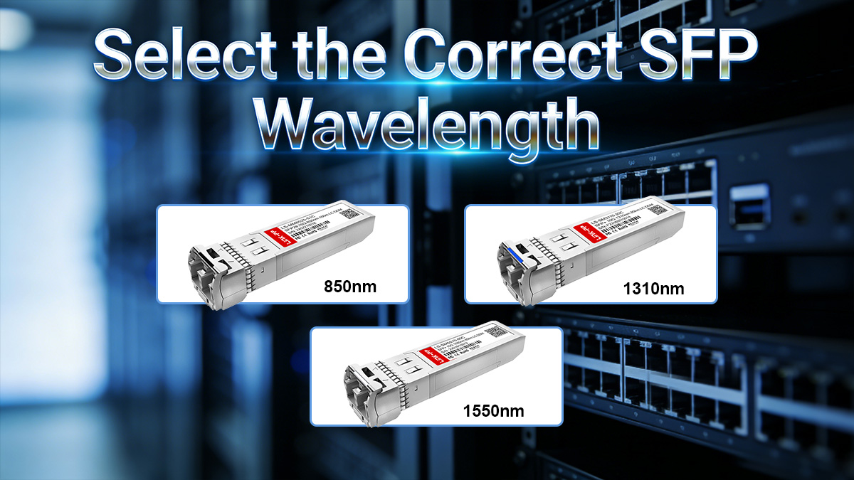
▶ Step 4 — Select the Correct SFP Wavelength (850nm, 1310nm, 1550nm)
Once compatibility, speed, and fiber type are determined, the next critical parameter is wavelength. The wavelength of an SFP module defines the light frequency used for optical transmission and directly affects distance, attenuation, and link quality. Selecting an incorrect wavelength can result in link failure or reduced performance.
Why Wavelength Matters in Fiber Networks
Wavelength selection is not arbitrary—it determines:
Transmission Distance: Certain wavelengths propagate with less loss over specific fiber types.
Modal Dispersion: Especially relevant in multi-mode fiber (MMF), where different light paths can arrive at different times.
Optical Budget: The combination of transmitter power, fiber loss, and receiver sensitivity depends on wavelength.
Compatibility: MMF SFP modules are designed for short-range 850nm links, while SMF modules operate at 1310nm or 1550nm for long distances.
In modern networks, incorrect wavelength selection is a leading cause of optical link failures.
850nm for Short-Range MMF
850nm SFP modules are typically used for:
Short-range connections (up to 550 meters depending on MMF type)
Multi-mode fiber (OM1–OM5)
High-density data center interconnects
Key considerations:
Works with both OM3 and OM4 for 10G and 25G links.
Power budget and connector quality can affect maximum achievable distance.
Generally cheaper than single-mode modules.
Example:
A 10GBASE-SR SFP module operating at 850nm over OM4 fiber can reliably reach 400 meters.
1310nm vs. 1550nm for SMF
For single-mode fiber (SMF), two primary wavelengths are used:
Wavelength | Max Distance | Typical Use Case |
|---|---|---|
1310nm | 10 km | Enterprise backbones, campus links |
1550nm | 40–80 km | Metro and carrier networks, long-haul DWDM |
Considerations:
1310nm: Lower attenuation than 850nm for SMF, cost-effective for short- to medium-range SMF links.
1550nm: Lowest attenuation and suitable for long-haul networks; often paired with optical amplification or DWDM.
Note: SMF SFP modules must match the fiber’s design wavelength to avoid excessive loss.
Common Mistakes in Wavelength Selection
Mixing MMF and SMF Wavelengths: Using a 1310nm module on MMF often fails due to higher modal dispersion.
Mismatched Link Ends: Both ends of the fiber must use SFP modules with the same wavelength and compatible optical power.
Ignoring Distance Limits: Choosing 850nm for a 10 km SMF link will not work; attenuation will prevent signal reception.
Assuming Longer Wavelength = Better: 1550nm is only advantageous for long distances; over short MMF links, 850nm is optimal.
Correct wavelength selection ensures optical performance, reduces errors, and maximizes link lifetime.
Next, we will cover Step 5 — Determine Required Transmission Distance, combining fiber type and wavelength into practical deployment guidance.
▶ Step 5 — Determine Required SFP Transmission Distance
After confirming compatibility, speed, fiber type, and wavelength, the next critical factor in SFP module selection is transmission distance. Each SFP module has a maximum supported distance determined by its optical power, the fiber type, wavelength, and link loss. Selecting a module that cannot cover the required distance will result in link failures or degraded performance.
Network planners must carefully match the module type to the physical link requirements.
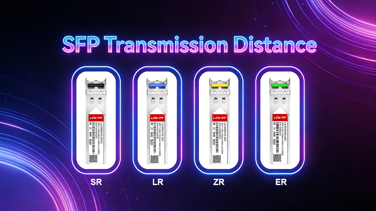
Typical Distance Mapping (SR, LR, ER, ZR)
SFP modules are often categorized based on their distance range:
Module Type | Wavelength | Fiber Type | Typical Distance | Common Use Case |
|---|---|---|---|---|
SR (Short Range) | 850nm | MMF | 0–550 m | Data center, intra-building links |
LR (Long Range) | 1310nm | SMF | 0–10 km | Campus backbones, enterprise networks |
ER (Extended Range) | 1550nm | SMF | 10–40 km | Metro networks, long-haul enterprise links |
ZR (Ultra Long Range) | 1550nm | SMF | 40–80 km | Carrier-grade networks, long-haul DWDM |
Key notes:
SR SFP modules are optimized for multi-mode fiber at 850nm; LR, ER, ZR are single-mode.
Optical attenuation, connector quality, and splicing impact achievable distances.
Always consider a safety margin for future fiber aging and network changes.
How to Choose SFP for 300m, 10km, 40km, 80km
A practical distance-based selection:
Link Distance | Recommended SFP Module | Fiber Type | Wavelength |
|---|---|---|---|
300 m | 10GBASE-SR | OM3/OM4 MMF | 850nm |
10 km | 10GBASE-LR | SMF | 1310nm |
40 km | 10GBASE-ER | SMF | 1550nm |
80 km | 10GBASE-ZR / DWDM | SMF | 1550nm |
Guidelines:
Determine actual fiber length, including patch panels and splices.
Select an SFP module that exceeds the link distance with margin.
Verify fiber type matches module (MMF or SMF).
Check wavelength compatibility with both ends of the link.
Power Budget and Link Margin Basics
The power budget is the difference between the transmitter output and the minimum receiver sensitivity. It determines how much optical loss the link can tolerate.
Formula:
Power Budget (dB) = Tx Output Power (dBm) – Rx Sensitivity (dBm)Losses in the link include:
Fiber attenuation (dB/km × length)
Connector loss (typically 0.3–0.5 dB per connector)
Splice loss (typically 0.1–0.3 dB per splice)
Contingency margin (1–3 dB recommended)
Link Margin:
Link Margin (dB) = Power Budget – Total Link LossPositive margin ensures reliable operation.
Negative margin indicates the SFP module cannot support the link distance.
Example:
Tx power = –3 dBm
Rx sensitivity = –17 dBm → Power Budget = 14 dB
Fiber loss = 8 dB, connectors = 1.5 dB, splices = 0.5 dB → Total Loss = 10 dB
Link Margin = 14 – 10 = 4 dB (sufficient for reliable operation)
Takeaway:
Always check both the distance and optical power budget when selecting SFP modules, especially for long-distance or high-speed links.
Next, we will cover Step 6 — Consider Operating Environment, which ensures your SFP modules operate reliably in commercial or industrial conditions.
▶ Step 6 — Consider Operating Environment (Commercial vs. Industrial SFP Modules)
After verifying compatibility, speed, fiber type, wavelength, and distance, it’s essential to consider the operating environment of your SFP modules. Temperature, humidity, vibration, and other environmental factors directly affect the reliability and lifespan of optical transceivers. Selecting the wrong type for your conditions can cause unexpected link failures or permanent module damage.
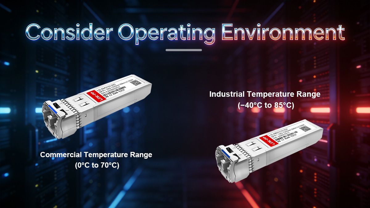
Commercial Temperature Range (0°C to 70°C)
Commercial-grade SFP modules are designed for standard office, data center, and indoor environments.
Key characteristics:
Operating temperature: 0°C to 70°C (32°F to 158°F)
Typical use cases: Enterprise switches, indoor patch panels, standard server racks
Lower cost compared to industrial modules
Limited tolerance to extreme heat, cold, or vibration
Commercial SFP modules are sufficient for most indoor installations where environmental conditions are controlled.
Industrial Temperature Range (−40°C to 85°C)
Industrial-grade SFP modules are engineered for harsh conditions, including outdoor or factory deployments.
Key characteristics:
Operating temperature: −40°C to 85°C (−40°F to 185°F)
Extended environmental tolerance for:
Extreme cold or heat
Dust, humidity, and vibration
Factory or industrial automation systems
Often include reinforced PCB and optics for higher reliability
Higher cost due to ruggedized construction
Industrial SFPs are commonly used in:
Industrial Ethernet networks
Outdoor fiber deployments
Transportation networks (railways, smart cities)
Harsh data center locations with extreme temperature swings
When to Choose Industrial SFP Modules
Choose industrial-grade SFPs if any of the following conditions apply:
Fiber is deployed in outdoor cabinets, street-side enclosures, or unconditioned spaces.
Environment experiences temperature extremes outside 0–70°C.
Applications require high reliability under vibration or shock, such as manufacturing floors or transportation systems.
Longevity and minimal maintenance are critical, especially in remote or difficult-to-access sites.
For controlled indoor environments with typical data center temperatures, commercial SFP modules are sufficient and cost-effective.
Correct environmental selection ensures your network maintains high availability and avoids unexpected downtime caused by module failure.
Next, we will discuss Step 7 — Decide If You Need DOM/DDM Monitoring, which is crucial for proactive network maintenance and troubleshooting.
▶ Step 7 — Decide If You Need DOM/DDM Monitoring
Once you have verified compatibility, speed, fiber type, wavelength, distance, and environmental requirements, the final consideration is monitoring capability. Many SFP modules include Digital Optical Monitoring (DOM) or Digital Diagnostic Monitoring (DDM), which provides real-time information about the module’s operating status. DOM is a valuable feature for network engineers who need proactive insight into link health and performance.
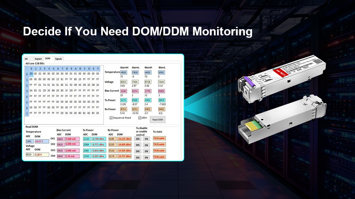
What Is Digital Optical Monitoring (DOM)?
Digital Optical Monitoring (DOM) is a standardized method for monitoring the operational parameters of an SFP module. It enables the switch or router to read module metrics via the I²C interface defined by the MSA.
Key benefits:
Real-time monitoring of optical transceivers
Early detection of potential link failures
Improved network reliability and troubleshooting efficiency
DOM does not replace compatibility checks or proper network design; it complements them by providing actionable operational data.
What Parameters DOM Tracks
DOM-capable SFP modules typically provide the following metrics:
Parameter | Description |
|---|---|
Transmit Optical Power (Tx) | Real-time output power of the laser |
Receive Optical Power (Rx) | Optical power received from the other end |
Module Temperature | Internal module temperature in °C |
Supply Voltage | Voltage level supplied to the module |
Laser Bias Current | Current driving the laser, indicating aging or degradation |
How this helps:
Sudden drops in Rx power may indicate fiber damage or dirty connectors
High temperature readings may signal insufficient cooling or environmental stress
Voltage fluctuations can indicate power supply issues
Network management systems (NMS) can log these values, trigger alarms, and generate reports to prevent downtime.
When DOM Is Required in Enterprise Networks
DOM is especially useful in environments where reliability, uptime, and preventive maintenance are critical:
Data Centers: Monitor high-density, high-speed links where failures affect multiple servers.
Carrier Networks: Track long-distance optical links to ensure service level agreements (SLAs).
Industrial Deployments: Identify early signs of stress in harsh environments.
Remote or Hard-to-Access Sites: Enables monitoring without physical inspection.
Guideline:
For small, short-range enterprise links, DOM may be optional.
For high-speed, long-distance, or mission-critical deployments, DOM is highly recommended.
Next, we will cover Frequently Asked Questions About Choosing SFP Modules, addressing common queries and capturing PAA (People Also Ask) search intent to improve SEO and AI citation potential.
▶ FAQs About Choosing SFP Modules
1. Can I use any SFP module?
No. While SFP modules follow MSA standards for form factor and electrical/optical interface, not all modules are universally compatible. Factors that affect usability include:
Vendor coding (firmware lock-in on certain switches)
Speed support (1G, 10G, 25G)
Fiber type (SMF vs MMF) and wavelength
Distance and optical budget
Always check your switch or router’s compatibility matrix and verify speed, fiber type, and environmental requirements before deployment.
2. How do I know if SFP is compatible?
Compatibility can be confirmed by:
Checking switch or router datasheets for supported SFP modules.
Confirming the form factor (SFP / SFP+ / SFP28).
Verifying vendor coding if the switch enforces it.
Matching Ethernet standard, speed, and fiber type.
Consulting firmware or software CLI commands to detect module recognition.
Proper verification prevents ports from remaining inactive due to unsupported transceivers.
3. Can you mix different SFP brands?
Yes, but with conditions:
Both modules must comply with the same Ethernet standard (e.g., 10GBASE-LR ↔ 10GBASE-LR).
Fiber type and wavelength must match.
Both ends must fall within the module’s power budget and distance range.
Vendor-coded modules may require EEPROM programming for firmware recognition.
Mixing brands is common in data centers, but always verify network documentation and test before deployment.
4. Which SFP module do I need?
Selecting the right SFP module depends on several parameters:
Compatibility: Vendor and MSA compliance
Speed: 1G (SFP), 10G (SFP+), 25G (SFP28)
Fiber Type: Single-mode (SMF) or multi-mode (MMF)
Wavelength: 850nm, 1310nm, 1550nm
Distance: SR (short), LR (long), ER/ZR (extended)
Operating Environment: Commercial (0–70°C) or Industrial (−40–85°C)
DOM/DDM Monitoring: Optional but recommended for mission-critical links
By evaluating these factors, you can determine the most suitable SFP module for your network link.
5. What is the difference between copper SFP and optical SFP?
Copper SFP (RJ45-based):
Uses twisted-pair Ethernet cable (Cat5e/Cat6/Cat6a).
Typically limited to 100 meters for 1G or 10G links.
Higher latency and power consumption for 10GBASE-T.
Lower upfront cost and easier installation in short-distance office networks.
Optical SFP (Fiber-based):
Uses fiber optic cabling (MMF or SMF).
Supports hundreds of meters to tens of kilometers.
Lower latency, longer distance, and higher bandwidth potential.
Preferred for data centers, campus networks, and carrier links.
6. Do SFP ports support both 1G and 10G?
It depends on the port type and switch capability:
SFP ports: Typically 1G only.
SFP+ ports: Primarily 10G, but many support 1G fallback.
SFP28 ports: Designed for 25G, may support 10G on certain hardware.
Always check your switch datasheet to confirm speed compatibility and fallback support.
▶ Final Recommendation — Choosing the Right SFP Module for 2026 Networks
Selecting the correct SFP module requires a structured approach that considers compatibility, speed, fiber type, wavelength, distance, environment, and monitoring capabilities. Networks in 2026 demand higher bandwidth, longer distances, and more reliability, making careful SFP selection critical for enterprise, data center, and industrial deployments.
By following the seven-step framework outlined in this guide, network engineers can:
Ensure full compatibility with switches and routers
Match module speed to network design (1G, 10G, 25G)
Choose the correct fiber type and wavelength for distance requirements
Account for operating temperature and environmental factors
Decide whether DOM/DDM monitoring is required for proactive network management
Proper planning avoids common pitfalls such as mismatched fiber type, unsupported vendor-coded modules, incorrect wavelength, or insufficient power budget.
Common SFP Selection Mistakes to Avoid
Ignoring Vendor Compatibility: Using an SFP Transceiver not recognized by the switch firmware.
Choosing the Wrong Speed: Installing a 10G SFP+ on a 1G-only port or vice versa.
Mismatched Fiber or Wavelength: Mixing single-mode and multi-mode or using the wrong wavelength.
Underestimating Distance: Failing to account for total link loss, splices, and connector attenuation.
Neglecting Environment: Using commercial-grade SFPs in industrial or outdoor deployments.
Skipping DOM/DDM Monitoring: Missing early warning signs of module degradation or link issues.
Avoiding these mistakes ensures stable, high-performance optical links that meet the demands of modern networks.
For reliable, high-quality SFP modules compatible with enterprise, data center, and industrial networks, visit the LINK-PP Official Store.


