1. Introduction
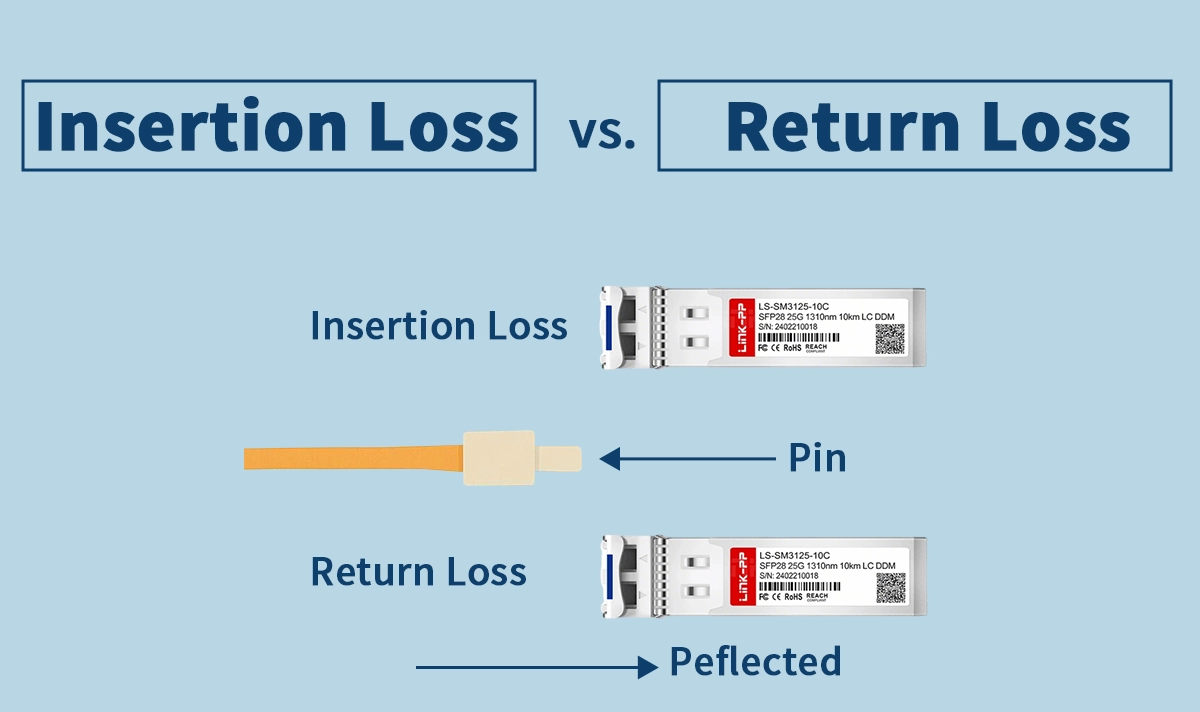
In fiber-optic networks, insertion loss (IL) and return loss (RL) are two critical metrics that every engineer must understand. While IL measures how much optical power is lost as it passes through a component, RL measures how much power is reflected back toward the transmitter. Both affect network performance but in different ways.
Choosing the right components, connectors, and transceivers depends on knowing these differences. This article compares insertion loss and return loss, explains when each matters, and provides practical guidance for deploying LINK-PP optical modules.
2. Understanding Insertion Loss
2.1 Definition
Insertion loss quantifies the reduction of optical power between the input and output of a device or fiber link.
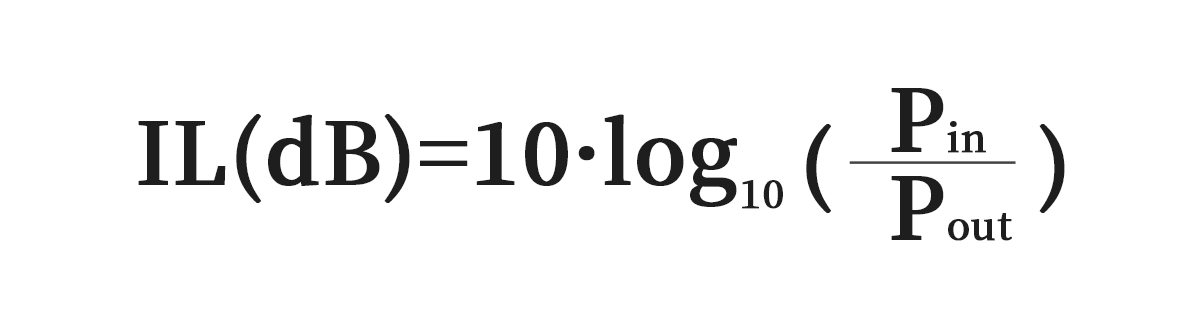
Lower IL is better; it means more light reaches the receiver.
Typical causes include connector loss, fiber attenuation, splices, and bending.
2.2 Why IL Matters
Directly reduces received power and link margin.
High IL can result in bit errors or link failure if the receiver falls below its sensitivity.
Critical for long-reach or budget-sensitive links.
Example:
A 10 km single-mode link with two connectors and a splice may have IL ≈ 2.4 dB. If the transmitter power minus IL is below receiver sensitivity, the link fails.
3 Understanding Return Loss
3.1 Definition
Return loss measures the amount of optical power reflected back toward the transmitter:
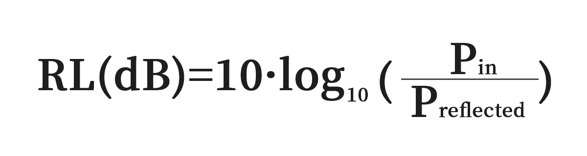
Higher RL (more dB) = less reflection = better.
RL protects the laser from back-reflected light that can destabilize the source.
3.2 Why RL Matters
Low RL (high reflections) can induce laser mode hopping, intensity noise, and increased BER.
Especially important for DWDM, analog RF-over-fiber, and sensitive long-reach transceivers.
Typical connector RL values:
PC: ~40 dB
UPC: ~50 dB
APC: ~60 dB or higher
4. Insertion Loss vs Return Loss: Key Differences
You need to understand the difference between return loss and insertion loss. Both affect your fiber optic network, but they measure different things. Return loss measures the amount of reflected signal, while insertion loss measures the forward signal loss as it passes through a component.
Feature | Insertion Loss (IL) | Return Loss (RL) |
|---|---|---|
Definition | Forward power loss | Back-reflected power |
Units | dB (smaller is better) | dB (larger is better) |
Impact | Reduces received power & margin | Affects laser stability & BER |
Measurement | OLTS, power meter | ORL meter, OTDR |
Critical For | Long links, multi-connector paths | Laser-sensitive, analog, DWDM links |
Key Insight: IL and RL are independent metrics — a component can have low IL but poor RL, and vice versa. Both must meet system requirements.
Insertion Loss Testing Steps:
Reference the power without the Device Under Test (DUT).
Insert the DUT.
Measure power loss.
Apply the IL formula.
Return Loss Testing Steps:
Inject light into the DUT.
Measure the reflected power.
Use the RL formula.
You may wonder how to test return loss in your network. The return loss testing procedure uses specialized instruments to measure reflectance and loss at each connection point. Testing return loss and insertion loss together gives you a complete picture of your network’s health. For example, a SFP28 BIDI transceiver may have an average insertion loss of about 1.8 dB and a return loss of less than -12 dB. These values show the device’s ability to maintain signal integrity over long distances. Different orl values can indicate how well your network handles reflectance and loss.
You should always monitor both return loss and insertion loss. This approach ensures you maintain high signal quality and reliable network performance.
5. Practical Scenarios
5.1 Scenario 1: Short Reach Data Center Link
IL is typically more important.
Reflection effects are minimal for robust digital receivers.
Example: Deploying LINK-PP LS-SW3110-02C in a 2 km 10G link with multiple connectors. Ensuring IL < 0.5 dB per connector preserves margin; RL > 26 dB is sufficient.
5.2 Scenario 2: Long Reach or DWDM Network
RL becomes critical. High-speed lasers (DFB/FP) are sensitive to reflections.
Example: 40 km DWDM link with APC connectors and a LINK-PP SFP28 25G module. Low reflection (RL ≥ 60 dB) ensures stable laser operation and low BER.
5.3 Scenario 3: Mixed Environment
Both IL and RL matter: IL for budget, RL for laser protection.
Engineers must measure IL via OLTS and RL via ORL meters and compare against module datasheet specifications.
6. LINK-PP Transceiver Guidance
LINK-PP modules are designed to provide consistent IL and RL performance. Examples include:
10G SFP+ LR: IL < 0.5 dB, RL ≥ 30 dB
25G SFP28 LR: Supports low-loss, low-reflection deployment for data centers
Engineering Tip: Always review the datasheet for IL and RL values before deployment, especially if multiple connectors or long distances are involved.
7. Best Practices for Network Deployment
Choose proper connector types: APC for reflection-sensitive links; UPC/PC for standard digital Ethernet.
Calculate link budget: Include all IL from connectors, splices, and fiber attenuation.
Test both metrics: OLTS for IL, ORL meter for RL.
Clean and inspect connectors: Dirt and scratches increase both IL and reflections.
Document baseline values: Useful for troubleshooting and maintenance.
8. FAQ
Q1: Can a module have low IL but poor RL?
A: Yes. A component may transmit light efficiently (low IL) but reflect back too much (poor RL), affecting laser stability.
Q2: Which metric is more important?
A: It depends on the application. Short-reach digital links prioritize IL, while laser-sensitive or long-reach networks prioritize RL.
Q3: How often should I test IL and RL?
A: At installation and after any major maintenance. High-criticality links may require periodic retesting.
9. Conclusion
Understanding both insertion loss and return loss is essential for designing, deploying, and maintaining high-performance optical networks. IL affects received power and link margin, while RL protects laser stability and reduces BER.
For engineers deploying LINK-PP optical modules, checking both IL and RL ensures reliable, high-speed links with predictable performance. By combining proper design, measurement, and maintenance, operators can achieve optimal network efficiency and longevity.


