
◆ Introduction
When discussing optical transceivers and fiber networks, engineers often focus on speed, wavelength, or reach. Yet another critical parameter—Return Loss (RL)—is sometimes overlooked, even though it can directly affect the stability of the light source and the overall performance of the network.
Return loss measures how much optical power is reflected back toward the transmitter due to imperfections at connectors, splices, or interfaces. In modern networks running at 10G, 100G, or even 800G speeds, poor RL can increase bit errors, reduce system reliability, and shorten component lifespan.
In this article, we explain what return loss is, why it matters, typical industry standards, and how LINK-PP optical modules are designed to achieve high return loss performance for demanding applications.
◆ Key Takeaways
Optical return loss (ORL) measures how much light reflects back in fiber optic systems. Higher ORL values indicate better transmission quality.
Regular testing of return loss is essential for maintaining network reliability. Use specialized instruments like OTDR and OCWR to check for issues.
To minimize return loss, clean connectors before use, use APC connectors, and follow best practices for fiber termination and maintenance.
◆ What is Return Loss?
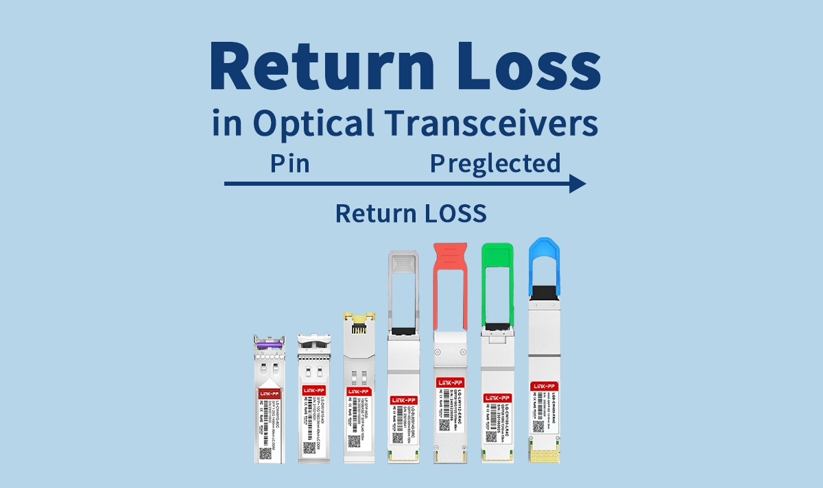
Return Loss (RL) describes the ratio of the incident optical power launched into a system compared to the power reflected back toward the source.
Definition:
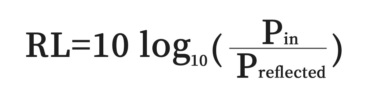
RL = 10 × log₁₀ (Pin / Preflected)Units: Decibels (dB)
Interpretation: A higher RL value indicates less reflected power and therefore better performance.
For example:
RL = 20 dB → 1% of power reflected
RL = 40 dB → 0.01% of power reflected
RL = 60 dB → almost negligible reflection
◆ Why Does Optical Return Loss Matter?
1. Laser Stability
Reflected optical power can re-enter the transmitter’s laser cavity, causing mode hopping, intensity noise, or frequency instability. This reduces signal integrity, especially in high-speed systems.
2. Bit Error Rate (BER)
Reflections introduce optical noise and jitter. At higher data rates (25G, 100G, or above), even small reflections can lead to significant BER increases.
3. System Reliability
Long-term exposure of lasers to reflected power accelerates aging, shortening the life of the optical transceiver.
4. Network Design Flexibility
By minimizing reflections, operators can use longer links, more connectors, or more complex passive optical components without performance degradation.
◆ Typical Return Loss Standards
Return loss requirements vary depending on the type of fiber connector and network application.
PC (Physical Contact) connectors: RL ≥ 40 dB
UPC (Ultra Physical Contact) connectors: RL ≥ 50 dB
APC (Angled Physical Contact) connectors: RL ≥ 60 dB
For optical transceivers:
Most IEEE and MSA standards specify RL ≥ 26 dB at the optical port.
In practice, high-performance modules achieve RL ≥ 30 dB or higher.
◆ Return Loss vs. Reflectance
While related, RL is often confused with reflectance.
Reflectance = ratio of reflected power to incident power (expressed as a negative dB value).
Return Loss = positive dB value, calculated as 10 log(Pin/Pref).
In short:
High return loss (e.g., 60 dB) = low reflectance (e.g., −60 dB).
◆ Causes of Poor Return Loss
Connector Surface Imperfections: Scratches, dirt, or poor polishing.
Air Gaps: Even tiny separations between connectors cause Fresnel reflections.
Mismatched Interfaces: Using PC with APC connectors leads to significant reflections.
Fiber Breaks or Bends: Physical issues in the fiber path reflect light back.
Low-quality Transceivers: Poor internal optical design may not sufficiently control reflections.
◆ Measuring Return Loss
You measure optical return loss using specialized instruments. Testing helps you verify the quality of your fiber optic connections and identify any issues with reflectance or loss.
Here are some common tools for testing return loss in optical fiber:
Instrument | Description |
|---|---|
OCWR (Optical Continuous Wave Reflectometer) | Measures reflectance or optical return loss of connectors. Used mainly for connector testing. |
OTDR (Optical Time Domain Reflectometer) | Uses backscattering to locate faults, optimize splices, and measure loss based on the backscatter coefficient and fiber loss. |
You should perform regular testing to ensure your network meets industry standards for return loss. For singlemode connectors, you want a minimum return loss of 55 dB, as recommended by IEC 61753-1. Multimode connectors should reach at least 35 dB. Adhering to these standards helps you avoid signal degradation and maintain high transmission quality.
As fiber optic technology evolves, innovations like ceramic ferrules improve alignment and reduce insertion loss. These advancements make it easier for you to manage optical return loss in glass fiber networks. LINK-PP optical transceiver products incorporate these technologies, giving you reliable performance and excellent ORL.
Note: Testing return loss in optical fiber is essential for maintaining network reliability. Always use calibrated instruments and follow best practices for accurate results.
◆ Best Practices to Improve Return Loss
Use APC connectors in sensitive DWDM, CATV, and high-speed applications.
Clean connectors properly with lint-free wipes and isopropyl alcohol.
Inspect and test with Optical Return Loss Meters (ORL meters).
Choose high-quality transceivers designed with reflection suppression.
◆ LINK-PP Optical Transceivers and Return Loss
LINK-PP engineers understand that return loss is not just a specification but a key factor in network stability. Our optical modules are designed to meet or exceed industry RL standards.
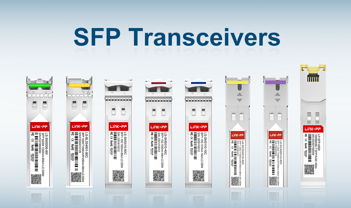
Example Products
10G SFP+ LR 1310nm – Ensures RL ≥ 30 dB for stable long-haul links up to 10 km.
25G SFP28 LR – High RL performance, ideal for data center interconnects.
100G QSFP28 CWDM4 – RL ≥ 30 dB, supporting demanding cloud and telecom deployments.
By maintaining strict quality control and advanced optical design, LINK-PP modules provide consistent performance even in environments where multiple connectors and splices are present.
◆ Conclusion
Return loss is one of the most important yet often misunderstood parameters in optical networks. High RL values ensure stable transmitters, low BER, and long component life.
By selecting optical modules with proven return loss performance, such as those from LINK-PP, network operators can build reliable, scalable infrastructures ready for next-generation data rates.
If you are planning a new deployment or upgrading existing links, consider the role of return loss carefully—and trust LINK-PP optical modules to keep your network stable and efficient.
◆ See Also
Understanding Optical Transceiver Failures: Key Problems And Solutions
An In-Depth Guide To Optical Transceiver Technology
Tips For Maintaining Consistent Performance Of Optical Transceivers
The Mechanism Behind Data Transmission In Optical Transceivers
Essential Certifications That Guarantee Optical Transceiver Quality


