

A SFP Bidirectional Transceiver (BiDi) is a small form-factor pluggable optical module that enables full-duplex data transmission over a single strand of single-mode fiber (SMF) by using two different wavelengths—one for transmit (Tx) and one for receive (Rx). Unlike conventional duplex SFP modules that require two fibers (one Tx and one Rx), a BiDi SFP integrates an internal wavelength division multiplexer (WDM) to separate and combine optical signals within the same fiber core.
This architecture allows network operators to effectively double fiber utilization without installing additional fiber infrastructure. As a result, BiDi SFP modules are widely deployed in fiber-constrained environments such as enterprise campus links, FTTx access networks, and metro edge connections.
BiDi SFPs are commonly available in standard Ethernet data rates such as 1G (1000BASE-BX) and 10G (10GBASE-BX), with typical reach options including 10 km, 20 km, and 40 km over single-mode fiber. Longer distances may be supported depending on optical budget and wavelength selection. Because transmission occurs over a single fiber using asymmetric wavelength pairs (for example, 1310 nm/1490 nm or 1270 nm/1330 nm), correct wavelength pairing between link endpoints is mandatory for proper operation.
From a standards perspective, BiDi SFP modules conform to the mechanical and electrical specifications defined by the Small Form Factor Multi-Source Agreement (SFP MSA) and typically support digital optical monitoring (DOM) as defined in SFF-8472. Ethernet optical parameters—such as launch power, receiver sensitivity, and dispersion limits—are aligned with relevant clauses in IEEE 802.3, depending on the specific data rate and reach class.
Understanding how Bidirectional SFP transceivers work—and how to validate wavelength pairing, compatibility, and optical power margins—is essential before deployment. Improper pairing, firmware incompatibility, or inadequate link budget calculation are among the most common causes of link failure in single-fiber optical systems.
This technical guide provides a structured, engineering-focused explanation of BiDi Bidirectional SFP principles, wavelength pairing strategies, compatibility considerations, link budget calculations, and deployment best practices.
⏩ What is a BiDi (SFP Bidirectional Transceiver)?
A BiDi (SFP Bidirectional Transceiver) is a pluggable optical module that enables full-duplex data transmission over a single strand of single-mode fiber (SMF) by using two different wavelengths—one for transmit (Tx) and one for receive (Rx). It achieves this by integrating an internal wavelength division multiplexer (WDM) that combines outgoing light and separates incoming light within the same fiber core.
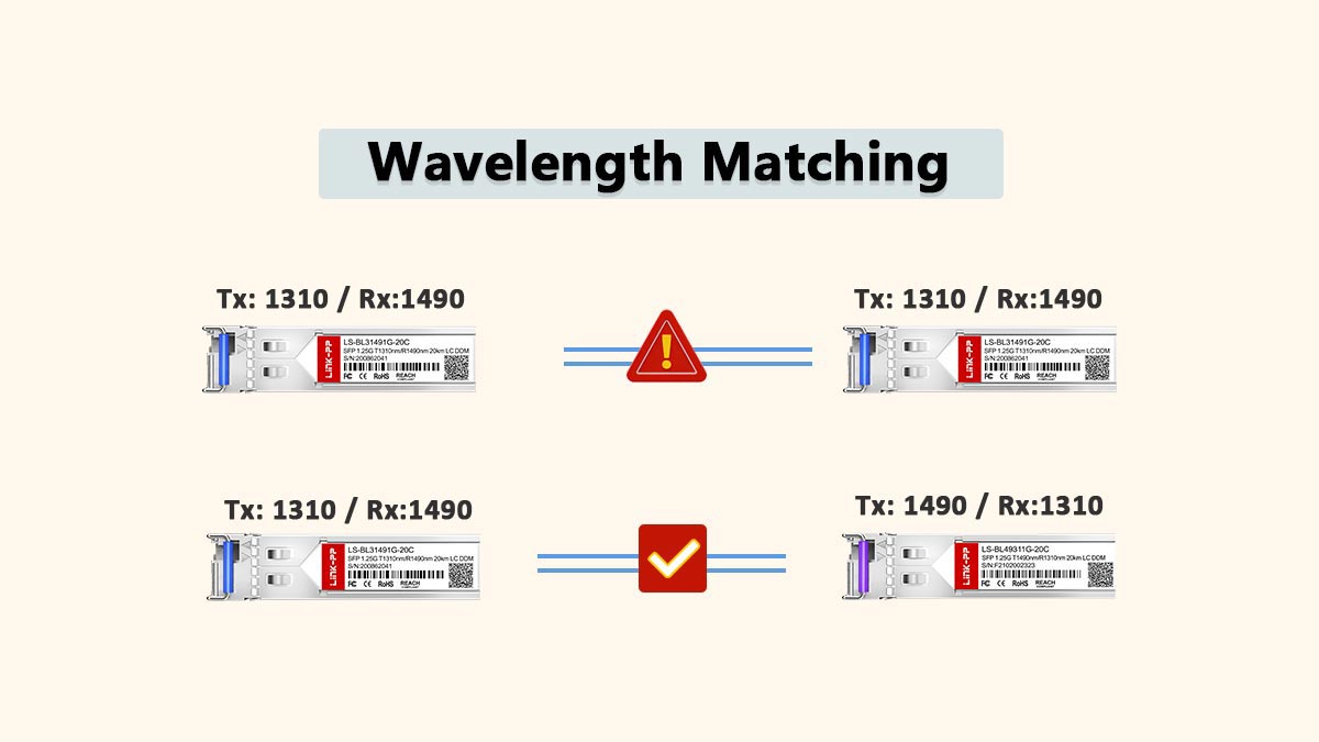
In a conventional duplex SFP deployment, two fibers are required—one dedicated to Tx and one to Rx. A BiDi SFP eliminates this requirement by assigning asymmetric wavelengths at each end of the link. For example, one module may transmit at 1310 nm and receive at 1490 nm, while its paired module transmits at 1490 nm and receives at 1310 nm. This complementary wavelength pairing is essential for proper operation.
Why BiDi SFPs Are Useful
The primary advantage of a BiDi SFP is single-fiber duplexing. By reducing fiber usage by 50% per link, it provides measurable benefits in fiber-sparse or cost-sensitive environments:
Fiber-constrained networks: Ideal for campus backbones, legacy buildings, and brownfield upgrades where spare fibers are limited.
Access and FTTx deployments: Efficient use of existing fiber infrastructure without additional cabling.
Cost optimization: Lower cabling and termination costs compared to deploying new fiber pairs.
Infrastructure scalability: Enables network expansion without modifying physical fiber plant.
BiDi SFP modules are commonly available in 1G and 10G data rates, with typical reach options such as 10 km, 20 km, and 40 km over single-mode fiber. Their mechanical and electrical characteristics conform to the Small Form Factor Multi-Source Agreement, while optical performance aligns with relevant clauses of IEEE 802.3 for the supported Ethernet variant.
In summary, a Bidirectional SFP is a wavelength-engineered optical transceiver designed to maximize fiber utilization while maintaining standard Ethernet performance over a single fiber strand.
⏩ How Bidirectional SFP Work: WDM and Laser Principles
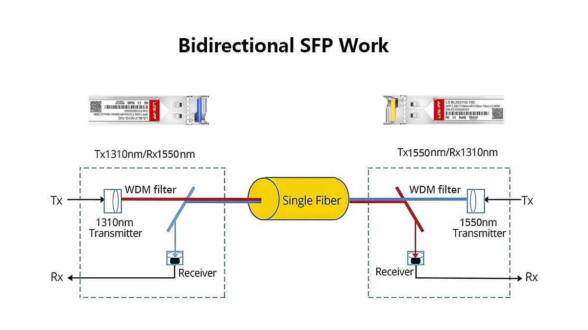
A Bidirectional SFP operates by transmitting and receiving optical signals on two different wavelengths over a single fiber, using an internal wavelength division multiplexing (WDM) filter to separate and combine light paths. This allows full-duplex Ethernet communication without requiring a second fiber strand.
WDM Optical Principle
Inside a Bidirectional SFP module, a miniature WDM coupler (optical filter) performs two functions:
Combining (multiplexing) the transmitted wavelength onto the fiber.
Separating (demultiplexing) the incoming wavelength from the same fiber.
The WDM filter is wavelength-selective. It reflects one wavelength toward the transmitter/receiver path while allowing the other wavelength to pass. This optical isolation ensures that the outgoing signal does not interfere with the incoming signal, even though both share the same fiber core.
This is fundamentally different from passive fiber splitting. BiDi modules rely on precise wavelength filtering, not time-division or power splitting.
Dual-Wavelength Transmission
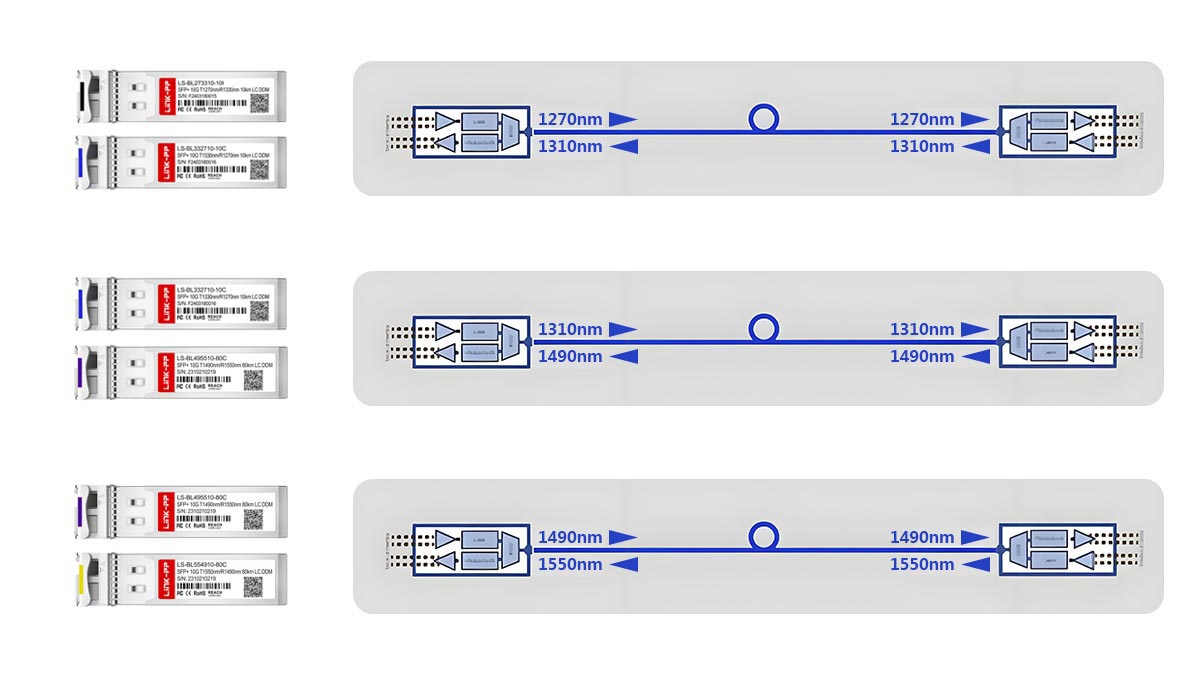
Each BiDi link requires a complementary wavelength pair. Common examples include:
1310 nm / 1490 nm
1270 nm / 1330 nm
1310 nm / 1550 nm
At one end of the link:
Tx = λ1
Rx = λ2
At the opposite end:
Tx = λ2
Rx = λ1
The transmit wavelength of one module must exactly match the receive wavelength of the module at the other end. Even if two modules share the same nominal distance rating (e.g., 10 km), mismatched wavelength pairing will prevent link establishment.
Because wavelength tolerances and launch power vary by vendor and reach class, engineers must always verify the exact wavelength specification in the SFP module datasheet before deployment.
Laser and Receiver Architecture
The optical source used in a BiDi SFP depends on the data rate and reach:
DFB (Distributed Feedback) lasers are typically used for 10 km and longer single-mode BiDi modules due to their narrow spectral width and stable wavelength performance.
FP (Fabry–Perot) lasers may be used in some short-reach 1G implementations.
VCSEL lasers are generally not used in long-reach single-mode BiDi modules; they are more common in short-range multimode optics (e.g., 850 nm applications).
On the receive side, the module includes a photodiode matched to the incoming wavelength band, along with a transimpedance amplifier (TIA) and limiting amplifier to recover the electrical signal.
Internal Tx/Rx Mapping Logic
Electrically, a BiDi SFP behaves like a standard duplex SFP:
The host device sends electrical transmit data (TX+ / TX−) to the module.
The module converts it into optical output at its assigned Tx wavelength.
Incoming optical data at the complementary wavelength is converted back into electrical RX+ / RX− signals for the host.
From the switch or router perspective, there is no logical difference between a BiDi SFP and a duplex SFP. The single-fiber behavior is entirely managed within the optical domain of the module.
Mechanically and electrically, BiDi SFP modules conform to the specifications defined in the Small Form Factor Multi-Source Agreement, while digital optical monitoring (if supported) follows SFF-8472.
In summary, a Bidirectional SFP module uses wavelength-selective filtering and precision laser control to enable two-direction Ethernet transmission over one fiber strand—without compromising full-duplex operation or Ethernet compliance.
⏩ BiDi SFP Wavelength Pairing and Types
Correct wavelength pairing is the most critical requirement in a Bidirectional SFP deployment. A BiDi link works only when the transmit wavelength (Tx) of one module matches the receive wavelength (Rx) of the module at the opposite end—and vice versa.
The Pairing Concept Explained
In a BiDi link:
End A:
Tx = λ1
Rx = λ2
End B:
Tx = λ2
Rx = λ1
This complementary configuration ensures that the optical signal transmitted from End A is received by End B at the correct wavelength, and the return traffic follows the opposite wavelength path.
If both ends use identical Tx wavelengths (for example, both transmitting at 1310 nm), the link will not establish because each receiver is tuned for a different wavelength band. BiDi modules are therefore always deployed in matched pairs, not as identical standalone units.
Common BiDi Wavelength Pairs
While exact values depend on vendor design and reach class, common single-mode BiDi SFP wavelength combinations include:
1310 nm / 1490 nm (widely used in 1G and some 10G variants)
1270 nm / 1330 nm (common in 10G BiDi deployments)
1310 nm / 1550 nm (used in certain longer-reach implementations)
For example:
Module Type A: Tx 1310 nm / Rx 1490 nm
Module Type B: Tx 1490 nm / Rx 1310 nm
These two modules must be installed at opposite ends of the same fiber.
It is important to note that wavelength designations are nominal center wavelengths. Actual laser emission has a specified tolerance (e.g., ±10 nm depending on design and data rate). Engineers should verify the exact wavelength range and spectral characteristics in the module datasheet.
Why Nominal Wavelength and Tolerance Matter
Even if two modules are labeled “1310 nm,” differences in center wavelength range, spectral width, or receiver passband may prevent interoperability. This becomes particularly important in:
Mixed-vendor environments
Long-reach (20 km / 40 km) deployments
Dense access or metro applications
For this reason, always confirm:
Nominal Tx wavelength
Wavelength tolerance range
Supported complementary pair
Receiver wavelength acceptance band
These parameters are defined according to relevant Ethernet optical specifications in IEEE 802.3 for the applicable data rate.
EEPROM Wavelength Identification
BiDi SFP modules store wavelength and identification information in their EEPROM memory map, defined by the Small Form Factor Multi-Source Agreement and digital monitoring extensions in SFF-8472.
Key EEPROM fields typically include:
Vendor name and part number
Vendor OUI
Nominal wavelength value
DOM capability flag
Network devices can read this information using CLI commands such as:
Verifying EEPROM-reported wavelength values before installation reduces the risk of incorrect pairing—especially in environments where multiple BiDi wavelength sets are stocked.
Engineering Best Practice
Always deploy Bidirectional modules in verified complementary pairs.
Physically label wavelength direction (e.g., “1310-TX”) to avoid confusion.
Confirm EEPROM wavelength values before installation.
Do not assume identical reach rating equals compatibility.
In BiDi deployments, wavelength pairing is not optional—it is the fundamental mechanism that enables single-fiber full-duplex operation.
⏩ Advantages and Limitations of Bidirectional Modules
SFP Bidirectional Transceivers provide a practical solution for maximizing fiber utilization, but their benefits come with specific engineering considerations. Understanding both advantages and constraints is essential before deployment.
Advantages of BiDi SFP Modules
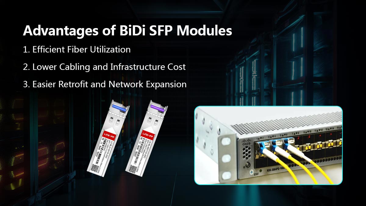
1. Efficient Fiber Utilization
The most significant advantage of a SFP Bidirectional Transceiver is that it enables full-duplex communication over a single strand of single-mode fiber. Compared to traditional duplex SFP optics that require two fibers per link, BiDi modules reduce fiber consumption by 50%.
This is particularly valuable in:
Fiber-constrained buildings
Legacy infrastructure with limited spare fibers
Access and aggregation layers
Campus or metro environments where new fiber installation is costly
2. Lower Cabling and Infrastructure Cost
Because only one fiber strand is required:
Fewer fiber cores are needed in backbone trunks
Patch panel density is reduced
Fewer termination points are required
While the unit price of a BiDi module may be slightly higher than a standard duplex SFP, the overall infrastructure cost is often lower when fiber installation, trenching, and splicing are considered.
3. Easier Retrofit and Network Expansion
BiDi SFP modules are especially useful in brownfield upgrades. Instead of pulling new duplex fiber, operators can:
Reuse existing single fibers
Increase link capacity without modifying physical infrastructure
Expand network services without major construction
Because Bidirectional modules follow the mechanical and electrical specifications of the MSA, they are physically interchangeable with standard SFP ports.
Limitations and Engineering Considerations
1. Wavelength Pairing Risk
Unlike standard duplex optics, BiDi modules must be deployed in complementary wavelength pairs. Incorrect pairing (e.g., installing identical Tx wavelengths at both ends) will prevent link establishment.
In environments where multiple wavelength combinations are stocked, misdeployment is a common operational risk. Proper labeling and inventory control are required.
2. Slightly Higher Module Cost
Bidirectional SFP modules integrate internal WDM filtering components and often use precision laser sources (commonly DFB lasers for longer reach). As a result, the module cost can be marginally higher than equivalent duplex SFP optics.
However, this cost difference is typically offset by fiber infrastructure savings.
3. Firmware and Compatibility Dependencies
Some network vendors enforce optical module validation through EEPROM checks. If the module identification fields do not match expected vendor profiles, the device may:
Generate warnings
Disable the interface
Limit DOM functionality
Compatibility depends on how the host device interprets EEPROM fields defined by the SFF-8472 and SFP MSA specifications. Third-party BiDi modules must be correctly coded for the target platform.
4. Reduced Margin in Poor Fiber Conditions
Because BiDi communication relies on precise wavelength filtering over a single fiber:
High attenuation
Excessive connector loss
Poor splice quality
Fiber aging or contamination
can reduce optical margin more noticeably than in short duplex links. While the optical budget is calculated the same way as standard SFP links, engineers must carefully validate link loss before deployment.
Practical Assessment
Bidirectional Transceivers are highly effective when:
Fiber availability is limited
Infrastructure cost reduction is a priority
Proper wavelength pairing procedures are followed
They require disciplined deployment practices—particularly regarding wavelength matching, firmware compatibility, and link budget verification—but when properly implemented, they deliver reliable and standards-compliant Ethernet performance over a single fiber strand.
⏩ Compatibility & EEPROM Coding for BiDi SFPs
Compatibility is one of the most important operational considerations when deploying a Bidirectional SFP. Although BiDi modules follow the mechanical and electrical definitions of the Small Form Factor MSA, host devices may enforce firmware-level validation based on EEPROM identification data.
EEPROM Memory Fields That Identify a BiDi Module
Each SFP module contains a serial EEPROM that stores standardized identification and diagnostic information. The memory map structure is defined by the SFP MSA, with digital diagnostics specified in SFF-8472.
Key EEPROM Fields in a SFP Bidirectional Transceiver
EEPROM Field | Technical Purpose | Why It Matters in BiDi Deployment |
|---|---|---|
Vendor Name | Manufacturer identifier string | Used by host devices to validate supported optics |
Vendor OUI (Organizationally Unique Identifier) | IEEE-assigned company identifier | Some platforms verify OUI for firmware acceptance |
Vendor Part Number (PN) | Specific optic model identifier | Determines reach, wavelength pair, and coding profile |
Serial Number | Unique manufacturing identifier | Enables traceability and lifecycle tracking |
Nominal Wavelength | Center Tx wavelength (e.g., 1310 nm, 1490 nm, 1550 nm) | Critical for correct complementary pairing |
Supported Data Rate | Rated signaling speed (1G, 10G, etc.) | Must match host interface capability |
DOM Capability Flag | Indicates Digital Optical Monitoring support | Enables real-time Tx/Rx power, temperature, voltage readings |
Transceiver Compliance Codes | Ethernet standard compliance identifiers | Confirms alignment with IEEE Ethernet specifications |
For BiDi modules, the nominal wavelength field is critical, as it identifies whether the module is the “A” or “B” side of a complementary pair (e.g., 1310-TX vs 1490-TX variant).
Vendor Locking and Firmware Enforcement
Some switch and router vendors implement firmware-level checks that validate EEPROM contents before enabling a port. Depending on platform and firmware version, the device may:
Accept the module without restriction
Generate a non-certified warning
Disable the port entirely
Restrict DOM monitoring access
Vendor OUI and part number fields are commonly used in this validation process. In certain environments, unsupported third-party modules may trigger system log messages or interface shutdown.
Compatibility behavior varies by vendor and software release. Therefore, always verify:
Approved optics list (if published)
Firmware version compatibility
Whether third-party optics are supported or configurable
Considerations for Third-Party BiDi Modules
When using third-party or compatible BiDi optics:
Ensure EEPROM fields are properly coded for the target platform
Confirm wavelength specification matches the required complementary pair
Validate DOM functionality is accessible
Test link stability under real traffic conditions
Even when a module is physically recognized, incorrect coding may affect monitoring visibility or generate system warnings.
Testing Bidirectional SFP Compatibility: Step-by-Step
A structured validation process reduces deployment risk. The following engineer-verified workflow is recommended.
Step 1 — Verify Compatibility List
Before installation:
Check the switch/router optics compatibility documentation
Confirm supported data rate (1G, 10G, etc.)
Confirm required BiDi wavelength pair
This step prevents unnecessary troubleshooting later.
Step 2 — Insert Module and Read EEPROM
After inserting the module, verify it is detected correctly.
Common CLI commands:
show interface transceiver
show inventory
show logging
Confirm:
Correct vendor identification
Correct part number
Nominal wavelength displayed
No error or “unsupported” messages in logs
If the module is not recognized, check firmware compatibility.
Step 3 — Verify DOM (Digital Optical Monitoring)
If the module supports DOM per SFF-8472, verify:
Tx optical power
Rx optical power
Module temperature
Supply voltage
Recommended engineering checks:
Tx power within vendor-specified range
Rx power above receiver sensitivity threshold
Rx power below overload limit
Temperature within operational range (commonly 0–70°C for commercial grade)
Example guideline (values vary by model):
Rx sensitivity: approx. −14 dBm (example for 10 km 1G class)
Rx overload: approx. −3 dBm
Always consult the specific datasheet for accurate thresholds.
Step 4 — Confirm Wavelength Pairing
Ensure that:
End A Tx wavelength matches End B Rx wavelength
End B Tx wavelength matches End A Rx wavelength
If the link does not come up but modules are recognized, wavelength mismatch is a common cause.
Step 5 — Confirm Link Establishment
Check interface status:
show interface statusVerify:
Link is up
No excessive error counters
No flapping events in logs
Step 6 — Perform Traffic and Stability Test
After link establishment:
Pass real traffic through the link
Monitor error counters (CRC, frame errors)
Observe DOM Rx power stability over time
Sustained optical power fluctuation may indicate marginal fiber quality or excessive connector loss.
Tips:
Always validate EEPROM information before production deployment
Confirm complementary wavelength pairing
Verify DOM readings against datasheet thresholds
Test under traffic load, not just link-up state
Document baseline Tx/Rx values for future troubleshooting
Proper compatibility validation ensures that a BiDi SFP operates reliably within defined optical and firmware constraints, minimizing operational risk in single-fiber deployments.
⏩ SFP Bidirectional Transceiver Deployment Checklist & Troubleshooting
Successful deployment of a Bidirectional SFP Module depends on disciplined validation. Because BiDi optics rely on complementary wavelength pairing and host acceptance logic, small configuration errors can prevent link establishment even when hardware is functional.
Below is a structured deployment checklist followed by common troubleshooting guidance.
Deployment Best Practices & Checklist
1. Confirm Fiber Type and Physical Condition
Verify the link uses single-mode fiber (SMF) only.
Confirm fiber grade (OS1 / OS2) is appropriate for the target reach (10 km / 20 km / 40 km).
Inspect connectors and clean LC interfaces before insertion.
Measure fiber length if uncertain.
Bidirectional modules designed for SMF should never be deployed over multimode fiber.
2. Verify Complementary Wavelength Pair
Before installation:
Confirm End A Tx wavelength matches End B Rx wavelength.
Confirm End B Tx wavelength matches End A Rx wavelength.
Physically label modules (e.g., “1310-TX” and “1490-TX”) to prevent mixing.
Incorrect wavelength pairing is the most common cause of link failure in BiDi deployments.
3. Validate EEPROM Identification
After inserting the module:
Confirm correct vendor and part number
Verify nominal wavelength
Confirm data rate compliance
Check DOM capability flag
EEPROM structure follows the SFF Multi-Source Agreement and digital diagnostics are defined in SFF-8472.
CLI examples:
show interface transceiver
show inventory
show logging
No “unsupported” or “invalid transceiver” messages should appear.
4. Calculate and Verify Link Budget
Before production activation:
Available Margin (dB) = Tx Output − Total Link Loss − Rx Sensitivity
Confirm:
Margin ≥ 3 dB (recommended engineering buffer)
Fiber attenuation aligns with wavelength used
Connector and splice losses are included
Never rely solely on nominal reach rating.
5. Verify DOM Values
Check:
Tx optical power within specification
Rx optical power above sensitivity threshold
Rx optical power below overload threshold
Stable readings over time
Record baseline DOM values (Tx, Rx, temperature, voltage) for future troubleshooting comparison.
6. Confirm Firmware Compatibility
Verify switch/router firmware version
Check vendor optics compatibility list
Confirm third-party modules are accepted
Some platforms may disable ports if EEPROM vendor fields do not match expected values.
7. Labeling and Spare Strategy
Operational best practice:
Label fiber strands and ports clearly
Label module wavelength direction
Keep spare complementary BiDi pairs in inventory
Store pairs together to avoid mixing A/B sides
Poor labeling often leads to repeated wavelength pairing errors.
Troubleshooting Common BiDi Issues
Below are typical field scenarios with direct engineering responses.
Q1: The link does not come up. What is the first thing to check?
Most common cause: wrong wavelength pair.
Action:
Verify Tx/Rx pairing at both ends
Swap one module with its complementary version if mismatched
Confirm EEPROM wavelength value via CLI
Q2: The interface shows “err-disabled” or “unsupported transceiver.”
Likely cause: firmware rejection due to EEPROM vendor check.
Action:
Check system logs (
show logging)Confirm optics compatibility documentation
Update firmware if applicable
Use correctly coded module for the platform
Q3: Rx power is too high and link becomes unstable.
Cause: receiver overload (short fiber distance with long-reach module).
Action:
Verify DOM Rx reading
Compare against receiver overload specification
Install an inline optical attenuator if required
Receiver overload is common when deploying 20 km or 40 km optics over very short fiber spans.
Q4: DOM information is not visible.
Possible causes:
Module does not support digital diagnostics
I²C communication issue
Firmware limitation
Action:
Confirm DOM support per SFF-8472
Reseat module
Check platform support
Q5: Link comes up but errors increase under load.
Likely causes:
Marginal optical budget
Dirty connectors
Excessive splice loss
Fiber aging
Action:
Recheck link budget
Clean connectors
Measure actual attenuation
Compare live DOM values with baseline records
Notes:
BiDi deployment success depends on five pillars:
Correct fiber type
Correct wavelength pairing
Valid EEPROM recognition
Sufficient optical margin
Firmware acceptance
When these are verified systematically, BiDi SFP modules provide stable and standards-compliant single-fiber Ethernet connectivity with predictable performance.
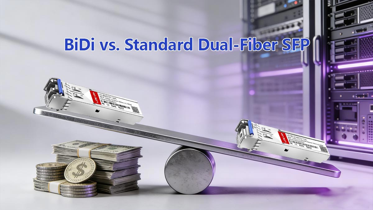
⏩ BiDi vs. Standard Dual-Fiber SFP: Cost & Operational Tradeoffs
Choosing between a single-fiber SFP (BiDi) and a standard dual-fiber SFP (Tx on one strand, Rx on another) is not purely a technical decision—it involves capital cost, operational risk, scalability, and lifecycle management considerations.
Below is a structured comparison for engineering and procurement evaluation.
1. Capital Expenditure (CapEx)
Fiber Infrastructure Cost
BiDi Advantage (Fiber-Constrained Environments)
Uses one fiber strand instead of two
Doubles usable capacity on existing fiber plant
Reduces cost in leased fiber or dark fiber environments
Avoids new trenching or fiber installation
In fiber-scarce environments (FTTx, metro edge, legacy campus), the savings from avoiding new fiber deployment often outweigh the slightly higher optic cost.
Transceiver Cost
Standard Dual-Fiber SFP Advantage (Module Cost)
Typically lower per-unit optic cost
Broader market availability
Simpler inventory management (no A/B pairing)
BiDi modules are usually priced slightly higher due to:
Integrated WDM filter
Complementary wavelength design
Lower production volume compared to standard 1310 nm duplex optics
2. Operational Expenditure (OpEx)
Installation & Field Operations
BiDi Considerations
Requires strict wavelength pairing (A ↔ B)
Higher risk of installation error
Requires careful labeling and inventory discipline
Dual-Fiber Simplicity
No wavelength pairing concerns
Reduced risk of mismatch
Faster swap and replacement process
Operational complexity is typically higher with BiDi unless procedures are standardized.
Inventory & Spare Management
Bidirectional optics must be stocked in complementary pairs.
Operational best practice requires:
Equal stock of each wavelength variant
Clear A/B labeling
Spare pairing policy
Dual-fiber optics simplify inventory because modules are identical at both ends.
3. Scalability & Lifecycle Planning
Fiber Scalability
BiDi significantly improves scalability where:
Fiber count is fixed
Fiber expansion is expensive or impossible
Existing conduit is saturated
In these environments, BiDi effectively doubles logical link capacity without new infrastructure.
Long-Term Network Evolution
Standard duplex optics offer:
Broader compatibility ecosystem
Wider support across vendors
Simpler migration paths to higher speeds
BiDi deployment must consider:
Future wavelength planning
Mixed environment management
Compatibility validation for upgrades
4. Diagnostics & Monitoring Considerations
Both BiDi and duplex SFP modules can support Digital Optical Monitoring (DOM) per SFF-8472.
However, operational differences include:
BiDi
Single fiber makes fault isolation slightly more complex
Cannot isolate physical strand issues (Tx and Rx share the same fiber)
Rx overload scenarios are more common in short-reach deployments
Dual-Fiber
Easier physical isolation of transmit vs receive path
More intuitive troubleshooting
From a diagnostics perspective, duplex optics are operationally simpler.
5. Risk Profile
Factor | BiDi | Dual-Fiber |
|---|---|---|
Fiber efficiency | High | Standard |
Module cost | Slightly higher | Lower |
Installation risk | Higher (pairing errors) | Low |
Inventory complexity | Moderate | Low |
Scalability in fiber-scarce sites | Excellent | Limited |
Troubleshooting simplicity | Moderate | High |
When to Choose BiDi
Bidirectional SFP is typically preferred when:
Fiber is limited or expensive
Retrofitting legacy single-fiber infrastructure
Expanding FTTx or metro access networks
Avoiding civil construction costs
When to Choose Standard Dual-Fiber SFP
Dual-fiber optics are often better when:
Fiber availability is abundant
Operational simplicity is priority
Large-scale data center deployments require uniform modules
Minimizing installation errors is critical
Engineering Conclusion
BiDi optics optimize fiber utilization efficiency, while dual-fiber optics optimize operational simplicity and standardization.
The correct choice depends on infrastructure constraints, operational maturity, and long-term network scaling strategy—not just initial transceiver pricing.
⏩ Final SFP Bidirectional Transceiver Recommendations & Deployment Guidance
A SFP Bidirectional Transceiver deployment can deliver significant fiber efficiency gains—but only when implemented with disciplined engineering validation. Below is a concise summary of field-proven recommendations.
Engineering Recommendations Summary
Validate the fundamentals before activation:
Confirm single-mode fiber (OS1 / OS2) compatibility
Verify complementary wavelength pairing (A ↔ B)
Check EEPROM fields (vendor, wavelength, data rate)
Confirm host firmware acceptance
Calculate optical link budget with ≥3 dB margin
Record baseline DOM values (Tx, Rx, temperature)
Never rely solely on nominal reach (10 km / 20 km / 40 km). Optical budget and pairing accuracy determine real-world stability.
Firmware & Wavelength Matching Reminders
BiDi reliability depends heavily on two operational controls:
A. Wavelength Discipline
End A Tx wavelength must match End B Rx
Modules must be deployed as complementary pairs
Always confirm nominal wavelength and tolerance via EEPROM readout
Wavelength mismatch remains the most common deployment failure cause.
B. Firmware & Vendor Coding
Verify switch/router firmware version
Confirm module compliance with Small Form Factor Multi-Source Agreement
Ensure DOM support per SFF-8472
Check vendor OUI and part number compatibility
Some platforms enforce strict EEPROM validation and may reject unsupported third-party optics.
Operational Best Practices
For production-grade networks:
Label fibers and ports clearly
Store complementary modules together
Maintain balanced spare inventory (both wavelength variants)
Log baseline DOM readings after installation
Periodically review Rx power against overload thresholds
These practices reduce troubleshooting time and prevent accidental wavelength mismatches during maintenance windows.
Deployment Strategy Recommendation
Choose BiDi when:
Fiber resources are constrained
Infrastructure retrofit is required
Metro, campus, or FTTx expansion must avoid new fiber construction
Choose dual-fiber optics when:
Fiber availability is abundant
Operational simplicity outweighs fiber savings
Standardized inventory management is a priority
A properly engineered BiDi deployment delivers long-term infrastructure efficiency without sacrificing performance.
Ready to Deploy SFP Bidirectional Transceiver?
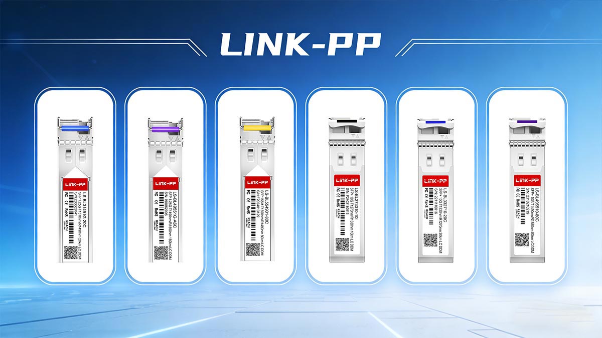
If you require fully tested, standards-compliant BiDi SFP modules with verified EEPROM coding and compatibility validation, explore the official product portfolio at: LINK-PP Official Store
Ensure your deployment starts with properly paired optics, validated firmware compatibility, and documented optical performance specifications.


