
In the intricate world of optical communications, where data travels at the speed of light as photons, a crucial electronic component works silently to translate this light-based information into the electrical signals our digital world understands. This component is the Transimpedance Amplifier (TIA). Often called the "first stage" of an optical receiver, the TIA's performance fundamentally dictates the sensitivity, bandwidth, and overall reliability of systems ranging from high-speed data center interconnects to fiber-to-the-home networks. Understanding "what is TIA in optics" is fundamental for anyone involved in photonics, optical networking, or high-speed electronics.
➣ What Exactly is a Transimpedance Amplifier (TIA)?
At its core, a Transimpedance Amplifier (TIA) is a specialized current-to-voltage converter. Its primary function is remarkably specific yet vital:
Receive Tiny Current: Accept an extremely small, fluctuating electrical current signal generated by a photodetector (like a PIN photodiode or Avalanche Photodiode (APD)) when struck by modulated light pulses.
Convert to Usable Voltage: Amplify this weak current signal and convert it into a robust, proportional output voltage signal large enough for further processing by subsequent stages (like a limiting amplifier or clock and data recovery circuit).
Maintain Fidelity: Perform this conversion with minimal added noise, maximum speed, and high linearity to preserve the integrity of the original optical data.
Essentially, the TIA bridges the gap between the optical domain (photons) and the electrical domain (voltage waveforms).
Key Mathematical Relationship:
The defining characteristic of a TIA is its Transimpedance Gain (Z_T), measured in Ohms (Ω) or Volts per Ampere (V/A).
V_out = I_in * Z_T
V_out = Output Voltage
I_in = Input Current (from the photodiode)
Z_T = Transimpedance Gain
A TIA with a gain of 1,000 V/A (or 1 kΩ) will produce a 1 mV output voltage for a 1 µA input photocurrent.
➣ Why TIAs are Non-Negotiable in Optical Systems
Photodiodes generate current, not voltage, proportional to the incident light power. This current is incredibly small, especially in high-speed or long-haul systems where received optical power can be very low (down to microwatts or less). Directly measuring such minute currents at GHz speeds with sufficient signal-to-noise ratio (SNR) is impractical. The TIA solves this critical problem:
Amplification: Boosts the weak signal to usable levels.
Low Noise: Adds minimal inherent noise, crucial for detecting weak signals.
High Bandwidth: Processes signals at the multi-GHz speeds required by modern optical links (e.g., 10G, 25G, 100G, 400G, 800G).
Impedance Matching: Provides a low input impedance, essential for maximizing the bandwidth of the photodiode itself, which has significant capacitance.
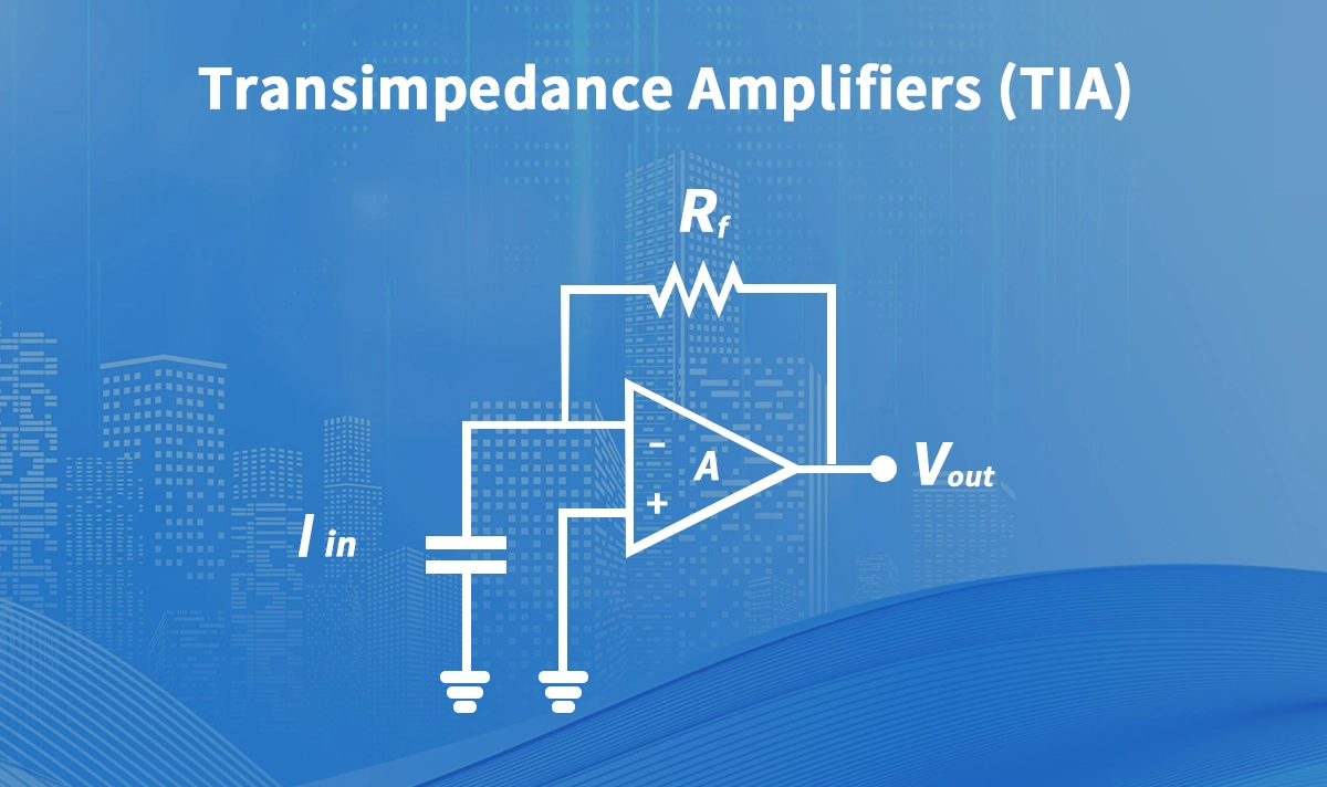
➣ Anatomy & Core Functionality: How a TIA Works
The most common and fundamental TIA topology is based on an inverting voltage operational amplifier (op-amp) with a feedback resistor (Rf) connecting the output back to the inverting input, where the photodiode is connected (usually in photovoltaic mode, cathode to the input).
Photodiode Current: Modulated light hits the photodiode, generating a proportional current
I_pd.Virtual Ground: The op-amp's high gain tries to keep the voltage at its inverting input (
V-) equal to the non-inverting input (V+), often grounded. This creates a "virtual ground" atV-.Feedback Path: The photocurrent
I_pdhas essentially only one path: through the feedback resistorRf.Voltage Generation: The current
I_pdflowing throughRfgenerates a voltage dropV_out = -I_pd * Rf(the negative sign indicates inversion). The op-amp's output adjusts to make this happen.Gain Setting: The transimpedance gain
Z_Tis primarily set byRf(Z_T ≈ Rffor an ideal op-amp).
Critical Design Elements & Trade-offs:
Feedback Resistor (Rf):
Larger Rf = Higher Gain = Better sensitivity for weak signals.
Smaller Rf = Potentially Wider Bandwidth (reduces time constant with photodiode capacitance).
Op-Amp Specifications: Requires very high gain-bandwidth product, ultra-low input noise (both voltage and current noise), low input capacitance, and high slew rate.
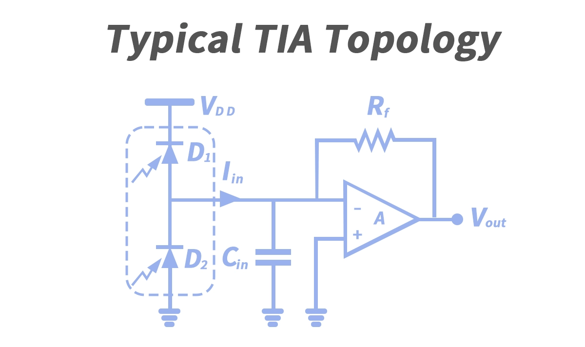
Stability: The interaction between the photodiode capacitance (
C_pd), the op-amp's input capacitance, andRfcreates a pole. Careful design (often involving a feedback capacitorCfin parallel withRf) is essential to prevent oscillation and ensure stability.Cflimits bandwidth but stabilizes the circuit.Noise Optimization: Balancing the thermal noise of
Rf(proportional to sqrt(Rf)) and the op-amp's input voltage/current noise is critical for achieving the lowest possible Total Input-Referred Noise (IRN). Lower IRN means better receiver sensitivity.
➣ Key Performance Parameters of an Optical TIA
Choosing or designing a TIA requires careful consideration of these interdependent specifications:
Parameter | Symbol/Unit | Importance | Typical Values/Considerations |
|---|---|---|---|
Transimpedance Gain | Z_T (Ω, V/A, dBΩ) | Determines output voltage level for a given input current. | Ranges from <100 Ω (high-speed) to >10 kΩ (sensitive, lower speed). Trade-off with bandwidth. |
Bandwidth | BW (Hz) | Maximum signal frequency the TIA can amplify without significant attenuation. | Must exceed the data rate (e.g., ~0.7 x Data Rate for NRZ). Critical for high-speed TIAs. |
Input-Referred Noise (IRN) | IRN (pA/√Hz) | Crucial for sensitivity! Noise "seen" at the input. Lower = better. | Dominated by |
Input Overload Current | I_ovl (mA peak or avg) | Maximum input current before distortion/saturation. | Protects the TIA and ensures linear operation under high optical power. |
Slew Rate | SR (V/ns) | Maximum rate of change of output voltage. Important for large signal swings. | Limits performance for large output signals or non-return-to-zero (NRZ) data with long runs. |
Power Consumption | P_diss (mW) | Critical for power-sensitive applications (e.g., pluggable modules). | Lower power TIAs enable energy-efficient SFP modules and dense deployments. |
Supply Voltage | Vdd (V) | Compatibility with system power rails. | Lower voltages (e.g., 3.3V, 1.8V) are common for modern, low-power designs. |
➣ Where TIAs Shine: Critical Applications in Optical Networking
TIAs are ubiquitous wherever optical signals are converted back to electrical signals:
Optical Receivers in Communication Links:
Datacom: SFP modules, SFP+, QSFP+, QSFP28, QSFP-DD, OSFP modules for data centers, enterprise networks. LINK-PP offers high-performance SFP optical modules like the SFP-10G-LR and SFP-10G-SR, incorporating ultra-low noise TIAs optimized for 25G and 50G PAM4 per lane applications.
Telecom: OLTs (Optical Line Terminals) in FTTH (Fiber-to-the-Home) / PON (Passive Optical Network - GPON, XGS-PON), line cards in routers and switches, long-haul/ultra-long-haul DWDM systems.
Optical Sensing: LIDAR (Light Detection and Ranging), fiber optic sensors (strain, temperature, pressure), biomedical imaging.
Test & Measurement Equipment: Optical power meters, lightwave signal analyzers, bit error rate testers (BERTs).
➣ TIA Integration in SFP Modules: A Closer Look
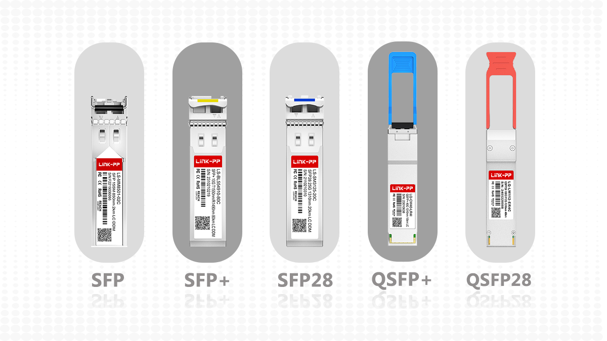
SFP modules (Small Form-factor Pluggable) and their faster variants (SFP+, QSFP28, etc.) are the workhorses of data center and enterprise optical connectivity. The TIA is a core component within the receiver side (Rx) of these modules:
Photodiode: Converts incoming optical signal to electrical current.
TIA: Converts the photodiode's weak current signal into a proportional voltage signal. Optimized for the module's specific data rate (e.g., 10G, 25G, 50G PAM4, 100G) and reach (SR, LR, ER, ZR).
Limiting Amplifier (LA) / Post Amplifier: Takes the TIA's analog output and amplifies it further to a consistent digital voltage level (e.g., CMOS or CML levels), often providing signal conditioning like peaking.
Clock and Data Recovery (CDR): (In higher-speed modules) Extracts a clean clock signal and retimes the data to reduce jitter.
Laser Driver & Laser Diode (Transmit Side): Handles the electrical-to-optical conversion for transmitting data.
Choosing the right TIA is paramount for SFP module performance: It directly impacts critical module specifications like receiver sensitivity, overload tolerance, power consumption, and bit error rate (BER). Leading manufacturers like LINK-PP meticulously select or co-design TIAs to ensure their SFP+ transceivers, QSFP28 modules, and next-generation 800G OSFP solutions meet stringent industry standards (MSA) and deliver reliable, high-performance connectivity.
➣ Design Challenges and Advancements in TIA Technology
Designing high-performance TIAs, especially for multi-gigabit rates and low power, involves overcoming significant hurdles:
Bandwidth vs. Gain vs. Noise Trade-off: This is the fundamental TIA design triangle. Increasing gain often reduces bandwidth or increases noise. Achieving high gain, wide bandwidth, and low noise simultaneously requires advanced circuit techniques (e.g., regulated cascode input stages, inductive peaking, multi-stage topologies).
Photodiode Capacitance (
C_pd): This capacitance, combined with the input resistance (effectivelyRffor gain), forms a low-pass filter limiting bandwidth (BW ≈ 1/(2πRf C_pd)). Large-area photodiodes (needed for coupling efficiency or high power handling) have higher capacitance, making high-speed design harder.Stability: As bandwidth increases, maintaining stability becomes more challenging. Precise modeling and compensation (using
Cf) are essential.Power Consumption: Demands for lower power in data centers drive TIA designs towards higher efficiency architectures and lower supply voltages.
Packaging & Parasitics: At GHz speeds, package inductance and capacitance significantly impact performance. Co-design of the TIA IC, photodiode, and package is crucial. LINK-PP's expertise in module integration ensures optimal RF performance.
Process Technology: Advanced semiconductor processes (SiGe, InP, deep-submicron CMOS) enable higher speeds, lower noise, and lower power consumption.
Recent Advancements:
Integrated TIAs with PDs: Monolithic integration of the photodiode and TIA on the same chip/die minimizes parasitics, improving bandwidth and noise.
Differential TIAs: Offer better common-mode noise rejection and are essential for PAM4 signaling.
TIAs with Integrated CDRs: Higher levels of integration for compactness and reduced power in modules.
Advanced BiCMOS/SiGe/InP Processes: Pushing bandwidth beyond 100 GHz per lane.
➣ Conclusion: The Indispensable Bridge in the Optical Path
The Transimpedance Amplifier (TIA) is far more than just a simple amplifier; it is the critical first stage that determines how effectively an optical receiver can translate faint pulses of light into robust, usable electrical data. Its performance in terms of gain, bandwidth, noise, and linearity sets the baseline for the sensitivity and data rate capabilities of the entire optical link, whether in a massive data center backbone, a metropolitan network, or an FTTx deployment. As data rates continue their relentless climb towards 1.6T and beyond, demanding innovations like coherent optics and advanced modulation formats (e.g., PAM4), the role of the TIA becomes even more challenging and vital.
Understanding "what is TIA in optics" provides foundational knowledge for anyone specifying, designing, or troubleshooting optical communication systems or their core components, such as the ubiquitous SFP module. The relentless pursuit of lower noise, higher bandwidth, and lower power TIAs remains a key driver of progress in optical networking.
Ready to Optimize Your Optical Systems?
Choosing the right TIA technology is critical for achieving peak performance in your optical links. Whether you're designing next-generation 400G/800G transceivers or specifying reliable SFP+ modules for your network upgrade, understanding TIA specifications is key.


