As 40 GbE networks continue to serve cloud platforms, hyperscale data centers, and high-density switching environments, the electrical interface between a host ASIC and a pluggable module becomes as important as the optical components themselves. One such interface, often referenced in 40 Gigabit QSFP+ datasheets, is XLPPI—the 40 Gigabit Parallel Physical Interface defined within the IEEE Ethernet architecture.
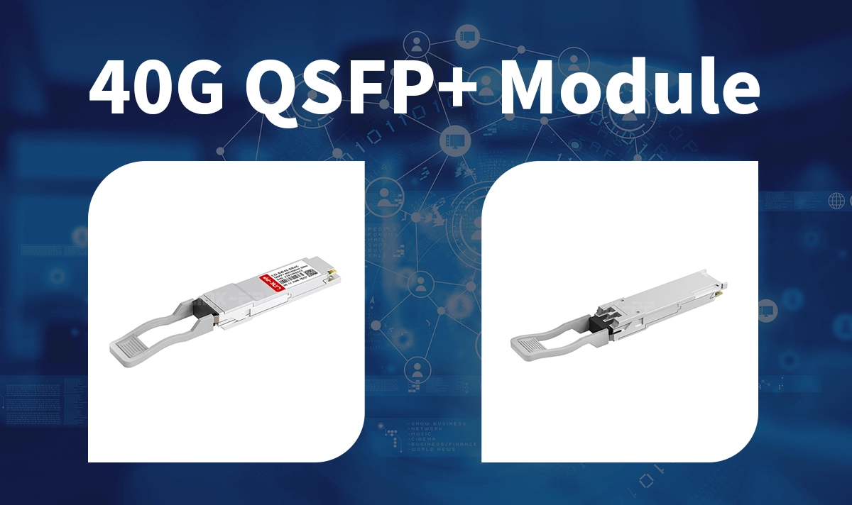
This article provides a clear, practical explanation of XLPPI and illustrates how it functions inside LINK-PP’s LQ-SW40-SR4C 40G QSFP+ SWDM transceiver, a widely used module for short-reach 40 Gbps MMF applications.
Key Takeaways
The XLPPI electrical interface uses four parallel channels to connect 40G QSFP+ modules to network hardware, enabling high-speed data transmission.
Understanding the XLPPI channel architecture helps in planning network layout and effectively troubleshooting signal issues.
XLPPI supports both fiber and copper modules, providing flexibility and compatibility for network design.
Maintaining signal stability is crucial to avoiding transmission errors; adhere to jitter and eye diagram requirements to ensure reliable performance.
When designing your data center, ensure your hardware supports XLPPI to enhance network scalability and make it future-proof.
✅ XLPPI Electrical Interface Overview

1. What Is XLPPI?
XLPPI (40G Parallel Physical Interface) is a four-lane electrical interface defined in the IEEE 802.3ba standards family for 40 Gb/s Ethernet. It establishes how a 40G PHY on the host side electrically communicates with a QSFP+ module.
2. Key characteristics of XLPPI
4 electrical lanes, each running at ~10.3125 Gb/s
CML differential signaling, optimized for high-speed PCB environments
Low-jitter requirements, with defined transmitter/receiver eye mask templates
Intended for chip-to-module links, not chip-to-chip interconnects
Forms part of the nPPI (n-lane Parallel Physical Interface) family defined by IEEE for pluggable optics
XLPPI allows a 40G link to be broken into manageable 10G-class lanes, reducing signal-integrity complexity while remaining interoperable across different module vendors.
3. Signal Rate and Channel Mapping
You need to know how the XLPPI electrical interface handles signal rates and channel mapping. Each lane operates at a fixed rate of about 10.3125 Gb/s. The interface splits your 40 Gbps data stream into four equal parts. This division keeps your signals synchronized and reduces the risk of errors.
The mapping process is straightforward. Your switch sends four electrical signals to the transceiver. Inside the module, each signal gets converted into a different optical wavelength. The module combines these wavelengths and sends them over a single fiber. At the other end, another module separates the signals and delivers them back as four electrical lanes.
Here is a table that shows how the four-lane structure works in practice:
Step | Description |
|---|---|
1 | The transceiver receives four electrical 10G lanes from your switch. |
2 | Each lane converts to a specific optical wavelength. |
3 | The module combines the four wavelengths onto one fiber. |
4 | The combined signal travels over the fiber cable. |
5 | Another module receives the signal. |
6 | The module separates the wavelengths. |
7 | Each wavelength converts back to an electrical lane for your switch. |
You benefit from this mapping because it supports high bandwidth and keeps your network flexible. The XLPPI electrical interface makes it possible for you to use both optical and copper modules in your 40 Gigabit ethernet setup.

✅ How XLPPI Operates Inside the LINK-PP LQ-SW40-SR4C QSFP+ Module
The LINK-PP LQ-SW40-SR4C is a 40G QSFP+ transceiver designed for short-reach multi-mode fiber using SWDM technology. The module incorporates:
4×10G electrical input/output lanes (XLPPI)
4 multiplexed wavelengths in the optical domain (SWDM4)
Duplex LC interface rather than MPO
Here’s how XLPPI integrates into the module’s internal data path:
▷ Host-to-Module Electrical Signaling
The switch or NIC ASIC sends four synchronized 10G data streams through the QSFP+ cage. These lanes comply with IEEE XLPPI electrical specifications, including amplitude, jitter tolerance, and AC-coupled differential signaling.
▷ Electrical-to-Optical Conversion
Inside the LQ-SW40-SR4C, the four XLPPI lanes feed a high-speed driver/gearbox and VCSEL array. The module combines the electrical data into four SWDM wavelengths, enabling 40 Gb/s over duplex multimode fiber.
▷ Reverse Process for Reception
On the RX side, the photodiodes demultiplex the incoming wavelengths, convert optical power into four 10G electrical lanes, and output them back to the host via the XLPPI interface.
▷ Why this matters
The use of XLPPI ensures the module remains interoperable with industry-standard 40G switches, avoiding proprietary interfaces and allowing predictable signal margins on high-speed PCB traces.
✅ Why 40G QSFP+ Uses XLPPI Instead of a Single High-Speed Lane
Designing a single-lane 40 Gb/s electrical interface would require significantly more complex SERDES, tighter jitter budgets, and expensive materials. XLPPI solves these challenges by:
Reducing per-lane signal rate to ~10 Gb/s, simplifying PCB routing
Lowering power consumption compared to high-speed serial PHYs
Allowing predictable performance over the host-to-module connector
Enabling hardware reusability, since many systems re-use 10G-class SERDES
This makes XLPPI ideal for compact, hot-pluggable modules like QSFP+.
✅ Benefits of XLPPI for System Designers and Integrators
1. Electrical Reliability
Four 10G lanes are far easier to maintain with acceptable eye-margin and crosstalk control than a single ultra-high-speed lane.
2. Module Interoperability
Because XLPPI is standardized, modules like the LINK-PP LQ-SW40-SR4C plug seamlessly into major switch platforms from Cisco, Arista, Juniper, and others.
3. Lower Design Costs
ASIC vendors can implement well-understood 10G-class SERDES, reducing development risk.
4. Scalability
XLPPI aligns with breakout applications (e.g., 40G-to-4×10G fan-out), commonly used in ToR switches.
✅ Comparing XLPPI to Other Interfaces
XLAUI and CPPI Differences
You may wonder how XLPPI compares to other electrical interfaces in high-speed networking. XLPPI, XLAUI, and CPPI each serve a specific role in Ethernet systems. You can see their differences more clearly when you look at their architecture and application.
XLPPI works as a chip-to-module interface. You use it mainly in 40G QSFP+ modules. It connects your switch or ASIC directly to the transceiver using four parallel lanes.
XLAUI acts as a chip-to-chip interface. You find it inside switches or routers, linking different chips together. It also uses four lanes, but you do not use it for direct module connections.
CPPI serves as a chip-to-module interface for 100G Ethernet. You use it in 100G modules, and it supports ten parallel lanes instead of four.
You can compare these interfaces in the table below:
Interface | Lane Count | Main Use Case | Connection Type |
|---|---|---|---|
XLPPI | 4 | Chip-to-module | |
XLAUI | 4 | Internal chip links | Chip-to-chip |
CPPI | 10 | Chip-to-module |
Note: XLPPI and CPPI are designed for chip-to-module connections, while XLAUI is for chip-to-chip links inside network equipment.
✅ Applications Enabled by XLPPI QSFP+ Modules
Spine/leaf architectures requiring 40G aggregation
TOR switches connecting to virtualization clusters
Campus backbone links using multimode fiber
40G-to-4×10G breakout cabling for legacy equipment integration
The LINK-PP LQ-SW40-SR4C is especially suited for short-range 40G SR-class deployments that need LC connectors but still depend on standardized 4×10G electrical signaling.
✅ Conclusion
The XLPPI electrical interface is a foundational technology for 40G QSFP+ transceivers. By dividing 40 Gb/s into four manageable 10G electrical lanes, it delivers a robust, interoperable, and standards-compliant link between host ASICs and pluggable optics.
In modules like the LINK-PP LQ-SW40-SR4C, XLPPI enables efficient electrical-to-optical conversion for SWDM-based 40G Ethernet, making the interface essential for modern data-center and enterprise networks seeking high density, low power, and reliable performance.
✅ FAQ
Q1. What does XLPPI stand for?
XLPPI means "40 Gigabit Parallel Physical Interface." You use it to connect your network switch or ASIC to a QSFP+ module. The interface uses four lanes for fast data transfer.
Q2. What makes XLPPI important for 40G QSFP+ modules?
You rely on XLPPI to ensure your module and host device work together. The standard supports high-speed data, easy upgrades, and flexible network design. You get reliable performance in dense environments.
Q3. What is the lane structure in XLPPI?
You see four parallel lanes in XLPPI. Each lane carries about 10.3125 gigabits per second. This structure lets you reach a total speed of 40 gigabits per second.
Tip: Understanding lane structure helps you troubleshoot signal issues.
Q4. What should you check for XLPPI compatibility?
You should confirm your switch, server, or router supports XLPPI. Look for modules that list XLPPI in their specifications. This step helps you avoid connection problems.
Q5. What is the difference between XLPPI and CPPI?
You use XLPPI for 40G modules with four lanes. CPPI works with 100G modules and uses ten lanes. Both connect chips to modules, but they support different speeds.
Interface | Lane Count | Speed |
|---|---|---|
XLPPI | 4 | 40Gbps |
CPPI | 10 | 100Gbps |
✅ See Also
Exploring The LINK-PP 10G SFP+ LS-SM5510-80C Transceiver
A Deep Dive Into LINK-PP LS-DW2810-40I 10G Transceiver
QSFP-DD Optical Transceivers Enabling High-Speed Connections


