

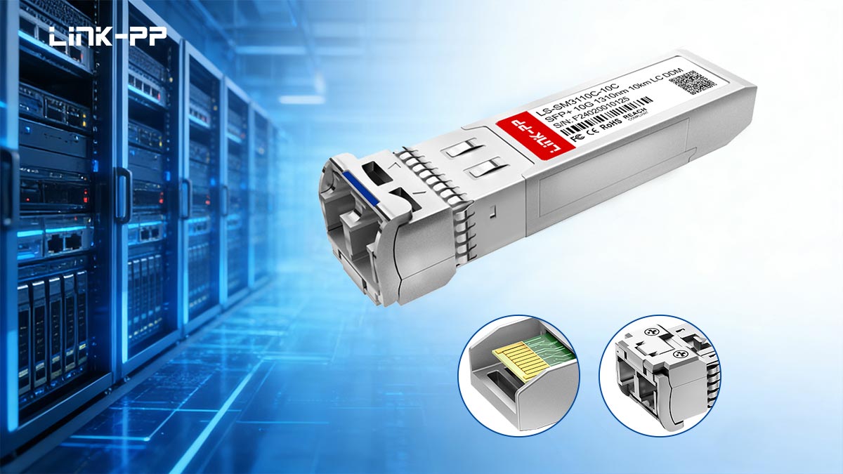
An LR SFP (10GBASE-LR) module is a single-mode optical transceiver that typically operates at ~1310 nm and provides reliable 10 Gb/s links up to 10 km over standard single-mode fiber (9/125 µm), used for campus backbones, inter-building links, and metro data-center interconnects.
LR matters because many real-world networks—such as campus backbones, inter-building connections, and short metro data center interconnects—exceed multimode limits but do not require extended-reach optics. This guide covers 10GBASE-LR technical specifications, link-budget calculation, vendor compatibility considerations, procurement checklists, deployment validation steps, and practical resources for reliable implementation.
🔹 What Is an LR SFP Module and Why It Matters
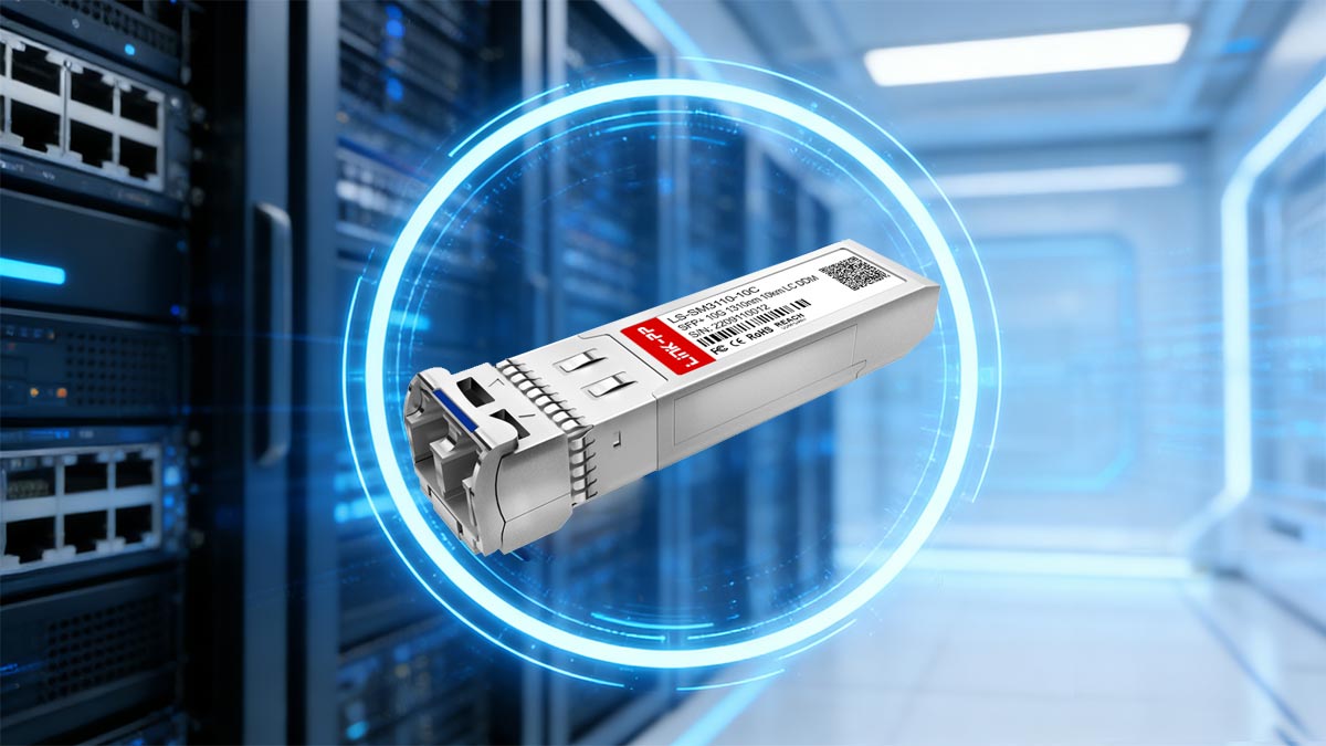
An LR SFP module implements the 10GBASE-LR physical layer defined in IEEE 802.3ae, using single-mode optics around ~1310 nm to support point-to-point 10 Gb/s Ethernet links up to 10 km over standard single-mode fiber (SMF). It is the industry-standard solution for building-to-building connections, campus backbone networks, and medium-reach aggregation links.
Under the 10GBASE-LR specification, the optical interface is designed for operation over 9/125 µm single-mode fiber, providing sufficient optical budget to maintain reliable transmission across typical campus or metro distances without amplification. Most LR SFP modules comply with the mechanical and electrical interface defined by SFF-8472 for Digital Optical Monitoring (DOM/DDM), enabling real-time reporting of transmit power, receive power, module temperature, supply voltage, and laser bias current.
Compared with short-reach SR optics (850 nm over multimode fiber), LR modules are optimized for lower fiber attenuation and longer spans. At ~1310 nm, typical fiber attenuation is significantly lower than multimode 850 nm systems, allowing links up to 10 km under standard link-budget assumptions as defined in IEEE performance parameters.
Key Characteristics of LR SFP Modules
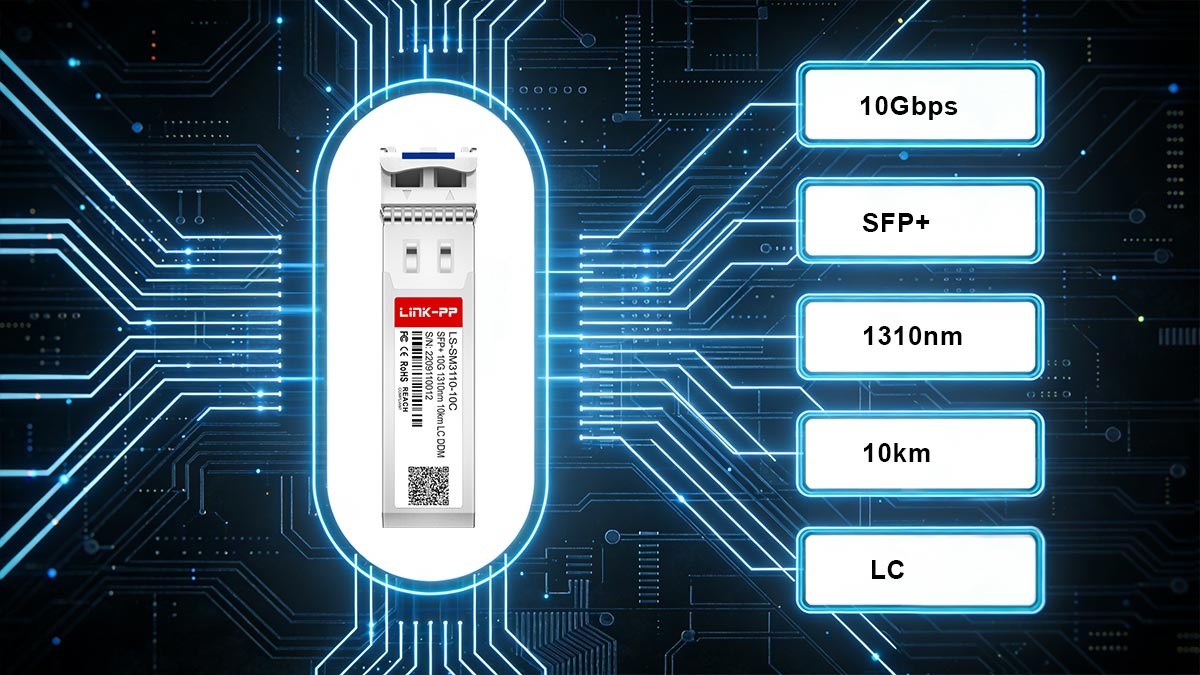
~1310 nm DFB transmitter or equivalent laser source
Typically uses a distributed feedback (DFB) laser optimized for single-mode transmission stability and spectral precision at 1310 nm.Single-mode fiber (9/125 µm) required
Designed specifically for SMF (OS1/OS2); operation over multimode fiber is not recommended without mode conditioning and is outside standard specification intent.Typical reach: up to 10 km (link-budget dependent)
Maximum distance assumes compliant fiber attenuation, connector loss limits, and adequate system margin per IEEE 802.3ae optical budget requirements.Moderate power consumption (~1.0–1.5 W typical)
Power draw varies by vendor and implementation but generally remains lower than extended-reach (ER) optics.Supports DOM/DDM per SFF-8472
Provides digital monitoring of Tx optical power, Rx optical power, module temperature, supply voltage, and laser bias current for operational diagnostics and predictive maintenance.
Why LR SFP Modules Matter in Real Networks
In modern network design, distance directly determines optical architecture. While short-reach (SR) optics dominate intra-rack and intra-row deployments, many enterprise and service-provider environments require reliable connectivity beyond a few hundred meters. This is where LR becomes critical.
Campus Backbones
Universities, hospitals, industrial parks, and corporate campuses often span multiple buildings separated by several kilometers. LR modules provide a cost-efficient and standards-based solution for inter-building backbone links up to 10 km, eliminating the need for higher-cost extended-reach optics.
Metro / Regional Aggregation (Short DCI)
For metro-area data center interconnects or regional aggregation links within 10 km, LR optics provide a stable single-mode solution without requiring amplification or dispersion compensation. In these scenarios, LR offers a balanced combination of optical budget, power efficiency, and cost control.
Enterprise Core & Distribution Layers
In three-tier or spine-leaf enterprise architectures, distribution-to-core links frequently exceed multimode limits. LR SFP modules allow organizations to standardize on single-mode fiber for medium-distance infrastructure while maintaining IEEE compliance and interoperability.
In short:
SR (850 nm, MMF) solves short data-hall links.
LR (~1310 nm, SMF) solves building-to-building and campus distances up to 10 km.
ER/ZR (~1550 nm, SMF) are reserved for longer metro or carrier-grade applications.
LR occupies the practical middle ground — technically robust, commercially accessible, and widely supported across switch vendors.
🔹 LR SFP Technical Specification Matrix
Below is a consolidated reference matrix for 10GBASE-LR SFP+ modules, aligned with the optical interface defined in IEEE 802.3ae and digital monitoring requirements in SFF-8472.
⚠️ Engineering note: Exact Tx/Rx optical values vary by vendor and module revision. Always verify against the specific manufacturer datasheet before performing final link-budget validation.
10GBASE-LR Specification Matrix
Parameter | Typical Value / Range |
|---|---|
Standard | 10GBASE-LR (IEEE 802.3ae) |
Wavelength | ~1310 nm |
Fiber | Single-mode fiber (9/125 µm, OS1/OS2) |
Tx Output Power (min) | Typically ~ -8 dBm to -3 dBm (vendor dependent) |
Rx Sensitivity | Typically ~ -14 dBm to -17 dBm (vendor dependent) |
Optical Budget (typical) | ~6–9 dB (module dependent) |
Maximum Reach | Up to 10 km |
Connector | Duplex LC |
Digital Monitoring (DOM/DDM) | Yes (per SFF-8472) |
Typical Power Consumption | ~1.0–1.5 W |
LR SFP Module Key Parameters Interpretation
Wavelength (~1310 nm)
SFP LR modules operate in the 1310 nm transmission window, where chromatic dispersion is minimal and fiber attenuation is lower than multimode systems at 850 nm. This enables reliable medium-distance transmission without dispersion compensation.
Transmit Power & Receiver Sensitivity
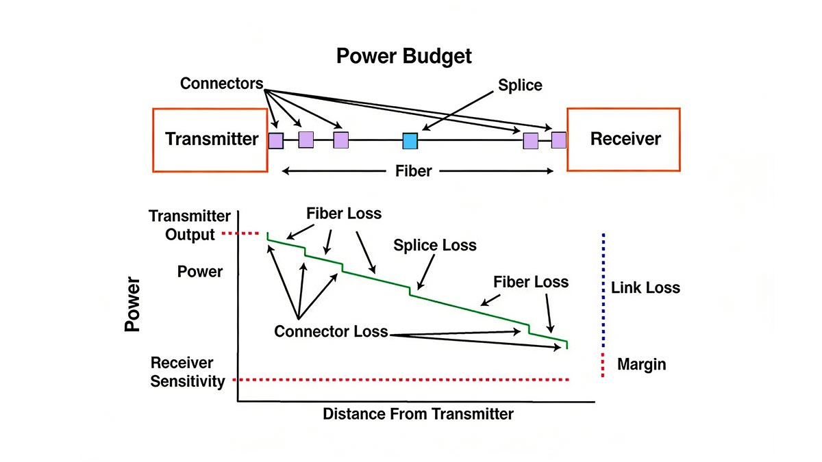
The effective link budget equals:
Minimum Tx Power – Maximum Receiver Sensitivity
For example, if a module specifies:
Tx (min): -8 dBm
Rx sensitivity: -14.4 dBm
The nominal budget is ~6.4 dB.
This must cover:
Fiber attenuation (~0.4 dB/km typical at 1310 nm for OS2)
Connector loss (~0.2–0.5 dB per mated pair)
Splice loss (if present)
Engineering safety margin (recommended ≥ 2 dB)
Maximum Reach (10 km)
The 10 km rating assumes compliant fiber, clean connectors, and IEEE-defined insertion loss limits. Real-world deployments should always validate actual span loss rather than relying solely on distance.
Power Consumption (~1.0–1.5 W)
LR modules draw more power than short-reach SR optics but significantly less than ER (40 km) optics. In high-density switches (32–48 ports), aggregate thermal load must be considered.
DOM/DDM Support
Per SFF-8472, LR modules typically support:
Tx optical power
Rx optical power
Module temperature
Supply voltage
Laser bias current
DOM readings are critical for commissioning validation and long-term predictive maintenance.
Procurement & Design Reminder for 10GBASE-LR
Optical transmit and receive specifications are not universal constants. Different manufacturers may provide slightly different output power windows, receiver thresholds, and internal safety margins while remaining IEEE-compliant.
Before deployment:
Obtain the exact vendor datasheet.
Perform a real link-loss calculation.
Confirm that worst-case Tx (min) still exceeds worst-case Rx (max) plus total path loss and safety margin.
Validate DOM thresholds after installation.
For mission-critical campus or metro links, formal link-budget verification should be treated as mandatory—not optional.
This specification matrix serves as an engineering reference baseline. Final deployment decisions should always be grounded in vendor-certified performance data and validated optical measurements.
🔹 LR vs. Other Fibre Classes (SR / ER / ZR)
LR occupies the medium-reach tier (~10 km) in 10G Ethernet optics; ER and ZR extend significantly farther with higher optical output power and cost, while SR is optimized for short-reach multimode links inside data halls.
In 10-Gigabit Ethernet defined under IEEE 802.3ae, optical variants are segmented primarily by wavelength, fiber type, and optical budget. Understanding these distinctions is critical for correct infrastructure design and cost control.
How They Differ Technically
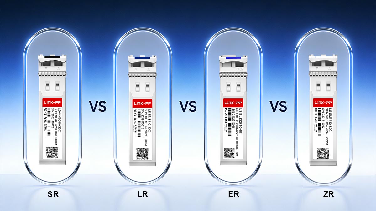
SR (10GBASE-SR)
Operates at ~850 nm
Designed for multimode fiber (OM3/OM4)
Typical reach: 300–400 m (up to ~550 m on OM4 under ideal conditions)
Lowest power consumption and lowest cost per port
Primary use: intra-rack, row-level, and data center switching
LR (10GBASE-LR)
Operates at ~1310 nm
Requires 9/125 µm single-mode fiber (OS1/OS2)
Reach: up to 10 km
Moderate optical output and power draw (~1–1.5 W typical)
Primary use: building-to-building, campus backbone, aggregation links
ER (10GBASE-ER)
Operates at ~1550 nm
Single-mode fiber
Reach: up to 40 km
Higher transmit power and tighter receiver thresholds
Higher module power consumption (~1.5–2.5 W typical)
Used for metro spans and longer regional links
ZR (10GBASE-ZR)
Not formally standardized by IEEE; vendor-defined extended reach
Typically 70–80 km
Higher optical budget and cost
Often used in carrier or long-haul applications
May require dispersion considerations and tighter link validation
ZR implementations are typically Multi-Source Agreement (MSA)-based rather than IEEE-defined, meaning interoperability should be verified carefully at both optical and firmware levels.
SR, LR and ER Quick Comparison Table
Parameter | SR | LR | ER |
|---|---|---|---|
Typical Reach | Up to ~300–550 m | Up to 10 km | Up to 40 km |
Fiber Type | Multimode (OM3/OM4) | Single-mode (OS1/OS2) | Single-mode (OS2) |
Typical Use Case | In-rack / data hall | Campus / building backbone | Metro / regional span |
Relative Cost | Lowest | Moderate | Higher |
Typical Power | ~0.7–1.0 W | ~1.0–1.5 W | ~1.5–2.5 W |
ZR modules typically exceed ER in reach (70–80 km) and cost, with higher optical output levels.
SR / LR / ER / ZR Selection Tips
From a design standpoint:
Choose SR when multimode fiber is already deployed and distance remains within data center limits.
Choose LR when distance exceeds multimode capability but remains within 10 km — this is the most common enterprise single-mode tier.
Choose ER/ZR only when the required span exceeds 10 km and fiber attenuation plus connector loss demand a higher optical budget.
LR is widely considered the default single-mode 10G standard, balancing reach, interoperability, power efficiency, and cost without the complexity of extended-reach optics.
In structured campus and metro environments, LR typically delivers the most favorable total cost of ownership while remaining fully compliant with IEEE 10G Ethernet optical specifications.
🔹 Typical LR SFP Module Deployment Scenarios (Use Cases)
LR SFP modules are typically deployed for campus backbones, inter-building fiber links, and short data center interconnect (DCI) spans up to 10 km, where single-mode transmission is required but extended-reach optics are unnecessary.
The 10GBASE-LR specification defined under IEEE 802.3ae positions LR as the practical medium-distance tier within 10G Ethernet architectures. In real-world network design, LR often represents the default single-mode optical solution for structured enterprise and metro environments.
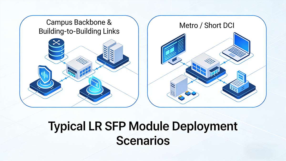
Campus Backbone & Building-to-Building Links
In enterprise campuses, universities, hospitals, and industrial parks, distances between buildings commonly range from several hundred meters to multiple kilometers. These spans exceed the practical limits of multimode SR optics and require single-mode fiber (9/125 µm, typically OS2 for outdoor or long indoor runs).
Typical infrastructure characteristics include:
Underground or aerial single-mode trunk cables
Fusion splices in handholes or intermediate distribution frames
LC duplex patch panels in main distribution frames (MDF) and intermediate distribution frames (IDF)
Cross-connect architectures for core-to-distribution aggregation
At ~1310 nm, fiber attenuation on OS2 is typically around 0.35–0.4 dB/km, allowing LR module (with a nominal 6–9 dB optical budget depending on vendor implementation) to support up to 10 km when connector and splice losses are properly controlled.
In these environments, LR offers:
Standards-based interoperability
Moderate power consumption compared to ER optics
Sufficient optical margin for structured campus pathways
Compatibility with common LC patching ecosystems
For most campus backbone designs within 10 km, LR is both technically adequate and economically optimized.
Metro / Short DCI Where LR Is Sufficient
In metro-area networks and certain data center interconnect (DCI) scenarios, facilities may be located several kilometers apart but still within 10 km fiber distance. When the span remains inside IEEE-defined LR optical budget limits, SFP 10G LR can be used directly without:
Optical amplification
Dispersion compensation modules
Coherent transport systems
This makes LR suitable for:
Enterprise-to-colocation connectivity within a metro zone
Short regional aggregation links
Secondary data center redundancy links
However, when span length exceeds 10 km—or when total insertion loss exceeds LR’s optical budget—designers must consider:
SFP 10G ER (40 km)
Vendor-specific ZR optics (~70–80 km)
Or dedicated DWDM transport platforms
Using LR beyond its designed optical envelope risks unstable links, marginal receive power, and reduced reliability under temperature variation.
10GBASE-LR Deployment Guidance
Before selecting LR for campus or metro use:
Measure or calculate total fiber attenuation (distance × dB/km).
Add connector and splice losses.
Include a safety margin (≥ 2 dB recommended).
Confirm worst-case transmit minimum exceeds worst-case receiver sensitivity plus total path loss.
When deployed within specification limits, LR SFP modules provide a highly stable and standards-compliant solution for medium-distance 10G Ethernet infrastructure.
🔹 LR SFP Module Link-Budget and Practical Planning
LR link validation requires confirming that minimum transmit power minus total optical path loss remains greater than receiver sensitivity plus engineering margin. For 10G-LR defined in IEEE 802.3ae, proper link-budget calculation is mandatory for stable operation up to 10 km over single-mode fiber.
How to Calculate Link Budget (Step-by-Step)
Use worst-case values from the SFP module datasheet (not typical values).
Step 1 — Identify optical specs
Tx (minimum output power, dBm)
Rx sensitivity (maximum receive threshold, dBm)
Step 2 — Calculate total optical loss
Fiber attenuation (dB/km × distance)
Connector insertion loss (dB per mated pair)
Splice loss (dB per splice)
Step 3 — Add engineering safety margin
Recommended: 2–3 dB
Step 4 — Validate inequality
Tx(min) − Total Loss ≥ Rx(sensitivity) + Margin
If the inequality is satisfied under worst-case conditions, the link is compliant.
Typical Loss Items & 8km Worked Example
1️⃣ Fiber Attenuation
For OS2 single-mode fiber at ~1310 nm:
Typical attenuation: 0.35–0.4 dB/km
For 8 km:
0.4 dB/km × 8 km = 3.2 dB2️⃣ Connector Loss
Typical LC duplex insertion loss:
0.2–0.5 dB per mated pair
Assume:
4 mated pairs (patch panel → distribution → core → remote end)
0.3 dB each
0.3 × 4 = 1.2 dB3️⃣ Splice Loss
Typical fusion splice loss:
~0.05–0.1 dB per splice
Assume:
6 splices
0.1 dB each
0.1 × 6 = 0.6 dB4️⃣ Subtotal Path Loss
Fiber:      3.2 dB
Connectors: 1.2 dB
Splices:    0.6 dB
--------------------
Subtotal:   5.0 dB
5️⃣ Add Contingency Margin
Recommended: 2–3 dB
Assume 2.5 dB:
Total Design Loss = 5.0 + 2.5 = 7.5 dB6️⃣ Validate Against Module Specs
Assume typical vendor worst-case values:
Tx(min): −8 dBm
Rx sensitivity: −14.4 dBm
Available optical budget:
−8 − (−14.4) = 6.4 dBRequired budget (from calculation):
7.5 dB⚠️ In this example, 6.4 dB < 7.5 dB, meaning the link may be marginal.
Engineering response options:
Reduce connector count
Improve insertion loss quality
Shorten span
Select higher-output LR variant
Consider ER optics if margin cannot be recovered
This demonstrates why relying solely on “10 km rated” is unsafe without full loss accounting.
DOM / Monitoring Thresholds in Production
Most LR SFP+ modules support Digital Optical Monitoring per SFF-8472. In production environments, the following parameters should be continuously monitored:
Key DOM Metrics
Tx optical power (dBm)
Rx optical power (dBm)
Module temperature
Supply voltage
Laser bias current
Recommended Operational Practices
Establish baseline Tx/Rx readings at commissioning.
Track long-term degradation trends.
Alert if Rx power approaches sensitivity threshold + margin.
Investigate sudden optical drops (possible dirty connectors or fiber stress).
Monitor temperature excursions in high-density chassis.
A common operational best practice is to trigger warnings if:
Measured Rx ≤ (Specified Sensitivity + 1 dB)This early-warning approach prevents unexpected link flaps.
LR Link-Budget Planning Summary
LR SFP modules provide up to 10 km reach over single-mode fiber, but distance alone does not guarantee compliance. Proper deployment requires:
Worst-case optical specification review
Full path-loss accounting
Conservative safety margin
Ongoing DOM-based validation
In structured campus and metro networks, disciplined link-budget planning is the difference between stable backbone performance and intermittent optical failures.
🔹 10GBASE-LR Compatibility & Vendor Considerations
Although 10GBASE-LR optics are standards-based under IEEE 802.3ae, many switch vendors enforce transceiver identification and firmware validation. Compatibility should always be verified before bulk procurement to avoid operational or support issues.
10GBASE-LR defines the optical interface (1310 nm, SMF, 10 km), but platform interoperability is not determined by optics alone. Vendors often implement EEPROM validation, digital diagnostics checks, and firmware-level restrictions that affect whether a module is accepted, flagged, or blocked.
Cisco / Arista / Juniper / HPE Compatibility Notes
Major vendors maintain official compatibility matrices and may apply platform-specific validation mechanisms:
Cisco Systems
Arista Networks
Hewlett Packard Enterprise
Practical procurement guidance:
Check the official compatibility matrix
Each vendor publishes supported transceiver part numbers per switch model and firmware version.Verify firmware caveats
Some platforms:Require specific minimum OS versions
Log warnings for non-OEM optics
Restrict DOM readings on unsupported modules
Understand reserved OEM features
Certain advanced capabilities (e.g., alarm thresholds, telemetry integration, power tuning) may be validated only for vendor-certified optics.Avoid cross-generation assumptions
A module supported on one switch family may not be supported on a newer hardware revision without firmware updates.
Even when optics are IEEE-compliant, switch software ultimately determines acceptance behavior.
EEPROM Coding and Vendor-Specific Flags
LR SFP+ modules contain EEPROM memory defined under SFF-8472 and electrical interface parameters under SFF-8431.
The EEPROM stores:
Vendor name
Vendor OUI
Part number
Serial number
Supported data rate
DOM capability flags
Alarm thresholds
Switches read these EEPROM fields during module initialization. Vendor-specific coding may include:
Approved OUI identifiers
Platform-validated part numbers
Checksum validation fields
Feature enablement flags
If the EEPROM does not match expected identifiers, platforms may:
Log “unsupported transceiver” warnings
Disable DOM access
Reduce port functionality
Block link activation (in rare strict-enforcement cases)
This is why “generic IEEE-compliant” does not always equal “operationally accepted.”
Risks of Unverified Third-Party LR Modules
Third-party optics can provide cost advantages, but risks increase when compatibility is not validated.
1. Unsupported Transceiver Messages
Switch CLI may display warnings such as:
Unsupported transceiver detectedWhile links may still pass traffic, this can:
Trigger NOC alerts
Cause compliance concerns
Complicate troubleshooting workflows
2. DOM Inaccuracies
If EEPROM calibration or alarm thresholds are not aligned with platform expectations:
Rx power readings may be offset
Alarm triggers may be unreliable
Temperature reporting may be inaccurate
This undermines predictive maintenance practices.
3. Firmware & Upgrade Sensitivity
After firmware upgrades:
Previously working third-party modules may be flagged
Compatibility checks may tighten
Support cases may require OEM optics for reproduction
4. Warranty & Support Implications
Some vendors may:
Require OEM optics during TAC troubleshooting
Request module removal during escalation
Decline root-cause confirmation if non-certified optics are present
Policies vary by vendor and service agreement.
Engineering & Procurement Practice for LR SFP Modules
Before large LR deployments:
Confirm IEEE optical compliance (10GBASE-LR).
Verify switch model + firmware compatibility.
Request coding confirmation from third-party suppliers.
Validate DOM readings in a pilot environment.
Maintain documented compatibility records.
LR optics are standards-based at the physical layer, but platform validation occurs at the firmware and EEPROM identification level. Procurement teams should treat compatibility verification as a mandatory pre-deployment step—not a post-installation troubleshooting activity.
🔹 Pricing, Supplier Selection & Deployment Validation for 10GBASE-LR
10GBASE-LR optics are typically priced higher than SR because they use single-mode laser technology and must meet tighter optical power specifications defined in IEEE 802.3ae. When procuring LR modules, total cost must consider component class (DFB vs. higher-grade optics), EEPROM coding, minimum order quantities (MOQ), and validation requirements—not just unit price.

Typical Price Ranges & Cost Drivers
LR SFP+ modules generally cost more than SR due to the following technical factors:
● Laser Type
Most LR modules use 1310 nm DFB (Distributed Feedback) lasers
DFB lasers are more complex and costly than VCSELs used in SR
Higher-stability bins or extended-temperature variants increase cost further.
● Optical Performance Binning
Modules must meet defined transmit power and receiver sensitivity ranges. Vendors may:
Bin lasers for tighter output ranges
Calibrate DOM thresholds
Conduct extended burn-in testing
Stricter qualification → higher cost.
● EEPROM Coding
Vendor-specific EEPROM programming under SFF-8472 and SFF-8431 may include:
Custom OUI
Platform-validated part numbers
Alarm threshold tuning
Custom coding batches often require MOQ commitments.
● Small-Volume Premiums
Low-quantity orders may incur:
Setup fees
Programming charges
Longer test queues
High-volume data center deployments benefit from scale pricing.
LR SFP Lead Time, MOQ, and Stock vs. Custom Coding
Procurement teams should clarify:
Stock modules
Pre-coded for major vendors
Shorter lead time
Limited customization
Custom-coded modules
Platform-specific EEPROM fields
May require 1–3 week production windows
MOQ may apply
For critical campus or metro deployments, maintaining buffer inventory is recommended to mitigate supply chain variability.
10GBASE-LR Modules Supplier Credibility Checklist
Before approving an LR supplier, verify:
ISO 9001 or equivalent quality certification
Optical test reports (Tx/Rx power validation)
Burn-in procedures (typically 24–72 hours)
DOM calibration documentation
Lot traceability and serial tracking
Clear RMA policy
For backbone applications, request:
Eye diagram test reports
BER test evidence
Environmental stress screening data
Optical compliance without process discipline increases long-term risk.
Implementation Best Practices & Validation Checklist
LR modules should always be validated in a lab environment before mass rollout. Production networks require optical instrumentation, DOM monitoring baselines, and proper documentation to prevent intermittent failures and troubleshooting delays.
Interoperability Testing (What to Test)
Before field deployment:
♦ Link Establishment
Confirm immediate link-up behavior
Verify auto-negotiation and FEC settings (if applicable)
♦ DOM Validation
Compare measured optical power vs datasheet range
Confirm alarm thresholds align with expectations
♦ BER Testing
Run sustained traffic under load
Confirm error-free operation (no CRC growth)
♦ Thermal Stability
Test under elevated ambient conditions
Monitor temperature drift and bias current stability
Interoperability should be verified across firmware versions if large-scale deployment is planned.
Optical Power Verification (How to Measure)
Even when DOM is available, direct measurement is recommended.
Required Tools
Calibrated optical power meter
Known-good reference patch cord
Procedure
Measure Tx output directly.
Measure received power at far end.
Compare measured loss with calculated link budget.
Validation formula reminder:
Tx(min) − Total Loss ≥ Rx(sensitivity) + Margin
Any discrepancy between expected and measured values should be investigated before production rollout.
Labeling, Asset Management & Inventory Control
Operational stability depends on documentation:
Label fiber pairs with distance and route ID
Record installed module serial numbers
Document firmware version at installation
Maintain compatibility matrix records
Inventory best practice:
Separate SR and LR stock clearly
Track coding type per batch
Maintain minimum safety stock for backbone optics
Structured asset tracking reduces MTTR during incident response.
LR vs. Alternatives — Decision Flow
When selecting optics, use the following engineering decision tree:
Step 1 — Distance
≤300 m over MMF → SR
≤10 km over SMF → LR
10–40 km → ER
40 km → ZR or coherent transport
Step 2 — Fiber Availability
Existing multimode → SR may be more economical
Only single-mode available → LR preferred
Step 3 — Budget Constraints
Short links + tight budget → DAC/AOC or SR
Medium reach backbone → LR balances cost and reach
Long metro spans → ER/ZR justified
Step 4 — Future Proofing
Expect campus expansion? Choose SMF + LR
Planning >10 km growth? Evaluate ER early
10GBASE-LR modules provide a balanced solution for campus and metro-scale networks. However, successful deployment depends on:
Careful supplier selection
Verified compatibility coding
Proper lab validation
Accurate link-budget measurement
Structured asset documentation
In backbone environments, procurement discipline and validation rigor are as important as optical specifications themselves.
🔹 LR SFP FAQs
Below are concise, standards-aligned answers to common 10GBASE-LR deployment and procurement questions. Technical references are based on IEEE 802.3ae and relevant SFP+ MSA specifications.
Q1: What distance does 10GBASE-LR support?
10GBASE-LR supports up to 10 km over single-mode fiber (SMF) at ~1310 nm, assuming compliant optical budget and proper link design.
Q2: Can 10GBASE-LR run over OM3/OM4 multimode fiber?
No. LR is designed for single-mode fiber (9/125 µm); multimode fiber causes severe modal dispersion and is not supported for standard LR operation.
Q3: What is the difference between LR and ER?
LR supports up to 10 km at 1310 nm, while ER supports up to 40 km with higher transmit power and tighter receiver specifications; ER optics are typically more expensive and power-hungry.
Q4: Do LR modules require special connectors?
Most LR SFP+ modules use duplex LC connectors; no special connector is required, but fiber must be single-mode (OS2 recommended).
Q5: Are third-party LR modules safe to use?
Yes, if properly coded and validated for the target platform; however, some switch vendors enforce EEPROM identification and may log warnings or restrict support.
Q6: What DOM metrics should I monitor?
Monitor Tx optical power, Rx optical power, module temperature, laser bias current, and supply voltage, as defined under SFF-8472.
Q7: How do you calculate link budget for LR?
Use the inequality:
Tx(min) − total path loss ≥ Rx(sensitivity) + engineering margin (2–3 dB recommended).
Include fiber attenuation, connector loss, splice loss, and contingency margin.
Q8: Can LR operate over dark fiber with high splice count?
Yes, provided total insertion loss remains within optical budget; excessive splices increase attenuation and may require margin reassessment or ER optics.
Q9: Does LR require forward error correction (FEC)?
Standard 10GBASE-LR per IEEE 802.3ae does not mandate FEC, but some platforms may support optional FEC modes depending on hardware design.
Q10: What happens if received power is too high?
If Rx optical power exceeds the maximum receiver threshold, the module may experience overload; optical attenuators can be used to bring levels within specification.
🔹 Final Recommendation for LR SFP Module Deployment & Procurement
The LR SFP module is the default single-mode optical choice for distances up to 10 km under IEEE 802.3ae. Before purchasing, always validate link budget calculations and confirm switch vendor compatibility to ensure stable long-term operation.
For campus backbones, inter-building links, and short metro spans, LR provides the optimal balance of reach, power consumption, and cost. However, deployment success depends on three engineering controls:
Verified optical loss calculation (Tx(min) − total loss ≥ Rx sensitivity + margin)
Platform firmware compatibility confirmation
Supplier quality validation (DOM calibration, burn-in, traceability)
Failure in any of these areas is more likely to cause instability than the optics standard itself.
Request a compatibility check or bulk quote for LR SFP modules — LINK-PP Official Store.
If you are planning a rollout, migration, or large-scale backbone upgrade, submit your switch model and firmware version to verify EEPROM coding and optical compliance before placing bulk orders.
SR Optics Resources, Datasheets & Tools
For engineering validation and procurement planning, consult the following resources:
📄 Standards & Technical References
IEEE 802.3ae — 10GBASE-LR optical specifications
SFF-8472 — Digital Optical Monitoring (DOM/DDM)
SFF-8431 — SFP+ electrical interface
📘 Vendor Datasheets
Review official datasheets for:
Tx minimum output power
Receiver sensitivity
Maximum receive power
Power consumption
Temperature range
Always use worst-case values for link-budget design.
🔎 Compatibility Matrix
Before procurement:
Confirm switch model + firmware version
Verify supported transceiver SKU
Check for firmware caveats or enforcement policies
Maintaining a documented compatibility matrix reduces troubleshooting time and avoids unsupported-transceiver warnings.
🧮 Downloadable Tools & Guides
LR vs SR/ER selection guide
Link-budget calculation worksheet (PDF)
Deployment validation checklist
Optical power verification quick reference
📝 Request Compatibility Check
Submit:
Switch vendor & model
Firmware version
Target distance
Fiber type (OS2, splice count, connector count)
Engineering validation prior to purchase minimizes deployment risk and accelerates rollout.
Note
The LR SFP module remains the industry standard for 10 km single-mode Ethernet connectivity. When selected with proper link budgeting, validated coding, and disciplined supplier screening, it delivers predictable backbone performance with minimal operational overhead.


