


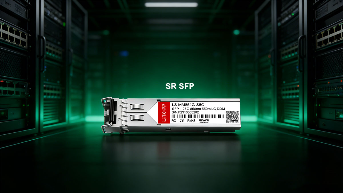
An SR (Short-Range) SFP/SFP+ module is a multimode optical transceiver designed for short-distance Ethernet links, typically operating at 850 nm over MMF. It is widely deployed in enterprise networks and data centers to provide cost-efficient, high-speed connectivity between switches, servers, and patch panels.
In modern high-density environments, SR optics remain the default choice for links inside racks, rows, and aggregation layers where distances generally fall within tens to hundreds of meters. Compared with single-mode alternatives, SR modules offer lower optical cost, simpler fiber infrastructure (OM3/OM4), and high port density—making them a practical baseline for 10G access and leaf-spine architectures.
This guide explains the key technical specifications, standards compliance, and real-world compatibility considerations for SR SFP/SFP+ modules, and provides a structured selection methodology to help engineers, purchasers, and network designers choose the correct optic for their deployment.
⏩ What Is an SR SFP Module?
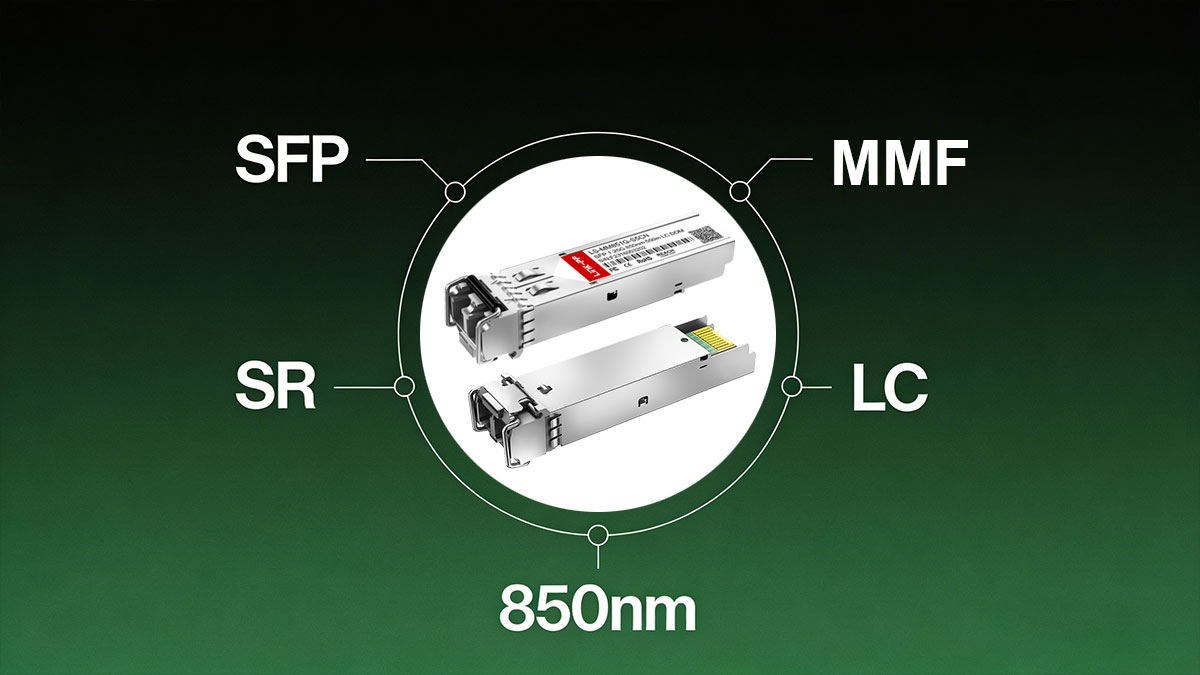
An SR SFP (Short-Reach Small Form-Factor Pluggable) module is an optical transceiver designed for short-distance Ethernet transmission over multimode fiber, typically operating at 850 nm using a VCSEL laser, and widely deployed in enterprise and data-center links for high-speed, cost-efficient connectivity.
Key Characteristics of SR SFP Module
● Multimode Fiber Operation
SR SFP modules are engineered for MMF (OM2/OM3/OM4) infrastructure, enabling simplified cabling within racks, rows, and equipment rooms where multimode fiber is already standardized.
● Short-Reach Transmission Distance
Typical reach depends on the Ethernet standard and fiber grade—for example, up to ~300 m on OM3 and up to ~400–550 m on OM4 for common SR variants such as 10GBASE-SR—making them ideal for intra-data-center connectivity.
● 850 nm VCSEL Optical Technology
Most SR modules use Vertical-Cavity Surface-Emitting Laser (VCSEL) sources at 850 nm, which provide stable performance, lower manufacturing cost, and efficient coupling into multimode fiber.
● Low Power Consumption
Compared with long-reach single-mode optics, SR SFP modules typically operate with lower optical output power and reduced electrical consumption, supporting high-density switch deployments.
● Cost-Efficient for High-Volume Deployment
Because multimode infrastructure and VCSEL components are economical at scale, SR SFP modules are widely selected for large-scale enterprise and hyperscale data-center environments where many short links are required.
⏩ SR SFP Technical Specifications
Core Optical Parameters of SR Modules
Short-reach (SR) SFP/SFP+ optical modules are designed for high-speed transmission over multimode fiber using an 850 nm VCSEL light source. Typical deployments use OM2, OM3, or OM4 MMF, with achievable distances varying by fiber grade and data rate.
Wavelength: Approximately 850 nm, typically generated by a VCSEL laser.
Fiber Type: Multimode fiber (OM2 / OM3 / OM4) commonly used in data-center interconnects.
Typical Reach:
Up to 300 m over OM3/OM4 for 10GBASE-SR deployments.
Up to ~550 m maximum reach is often cited for lower-speed multimode SR implementations (e.g., Gigabit SX class).
These distance variations depend on modal bandwidth, connector loss, and link budget design.
Standard Compliance of Short-reach Optical Modules
SR SFP modules typically comply with widely adopted Ethernet and management standards:
IEEE 802.3 Ethernet Families
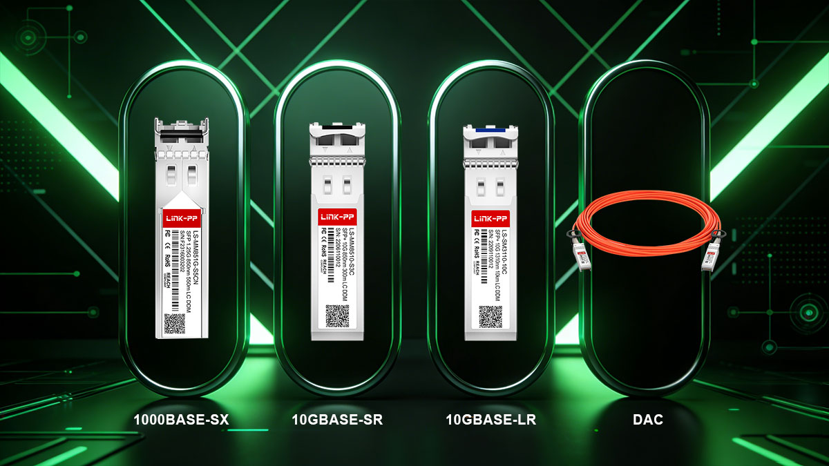
1000BASE-SX for Gigabit multimode links
10GBASE-SR for 10-Gigabit short-reach data-center interconnects
SFF-8472 Digital Diagnostics Monitoring (DOM)
Enables real-time monitoring of Tx/Rx optical power, temperature, voltage, and laser bias for predictive maintenance and link validation.
Most commercially available SR modules are also MSA-compliant for interoperability across switch and NIC vendors.
SR SFP Module Specification Table
Standard | Wavelength | Fiber Type | Typical Reach | Connector | Typical Power Consumption |
|---|---|---|---|---|---|
1000BASE-SX (SFP) | ~850 nm | OM2 / OM3 MMF | Up to ~550 m (fiber-dependent) | Duplex LC | ~0.5 W (typical class devices) |
10GBASE-SR (SFP+) | ~850 nm | OM3 / OM4 MMF | ~300 m (OM3), up to ~400 m (OM4 in optimized links) | Duplex LC | Low-power design, commonly around sub-1 W class |
⏩ Common SR SFP Module Variants on the Market
To avoid a purely encyclopedic page and better serve engineers and procurement teams, this section outlines the most common Short-Reach (SR) SFP/SFP+ variants, their typical reach and use cases, and how they compare with “Long-Range” alternatives.
1. 1000BASE-SX SFP
Typical Reach
Depending on multimode fiber grade, 1000BASE-SX can support up to approximately:
~220 m on older OM1/OM2 fiber
~550 m on OM3/OM4 fiber under ideal conditions
Typical Use
Short-distance Gigabit Ethernet links within the same equipment room
Server uplinks, switch interconnects, and access layer links in enterprise networks
A cost-effective choice where 1G bandwidth remains sufficient and existing multimode infrastructure is in place
Notes for Procurement and Deployment
SX optics are usually lower cost than their 10G counterparts
Ensure fiber grade supports the intended reach before purchase
2. 10GBASE-SR SFP+
Typical Reach
Designed for 10 Gigabit Ethernet over multimode fiber
Approximate reach:
~300 m over OM3
~400 m (or more) over OM4 multimode fiber
Typical Use
Data center Top-of-Rack (ToR) switch uplinks
Leaf-spine interconnect fabrics
Short intra-row or intra-pod optical links where high-speed connectivity is required but distance is limited
Why It’s Widely Adopted
Balances performance, cost, and ease of deployment
Low power consumption compared to longer-reach optics
Works well with DOM/DDM for active monitoring and maintenance
3. SR vs. LR Quick Comparison
This comparison helps align module choice with deployment needs and budget:
Feature | SR (Short-Reach) | LR (Long-Range) |
|---|---|---|
Medium | Multimode Fiber (MMF) | Single-Mode Fiber (SMF) |
Typical Reach | ~300–400 m | Up to ~10 km |
Wavelength | ~850 nm | ~1310 nm |
Cost Profile | Lower cost, lower power | Higher cost, higher power |
Typical Use Cases | In-rack / short data hall links | Campus / building backbone |
MMF (Multimode) is optimized for short distance, higher numerical aperture fiber types (OM2/OM3/OM4), providing cost efficiencies for short-reach links.
SMF (Single-Mode) supports larger distances with a smaller core and higher optical budget, at increased transceiver cost.
Distance
SR modules are purpose-built for short distances inside data halls or within campus clusters.
LR modules are designed for distances beyond MMF limits, such as inter-building links.
Cost Profile
SR optics and multimode cabling are generally more economical than LR optics and single-mode fiber when distance requirements permit.
LR optics typically consume more power and have a larger optical budget, increasing both component and operational costs.
4. SR SFP vs. Other Short-Reach Options
★ SR vs. DAC
When comparing SR SFP modules to DAC (Direct Attach Copper) cables, the primary difference lies in the medium used and the deployment environment. SR SFP modules, which use multimode fiber, are ideal for environments where longer distances (up to 300-400 meters) and fiber infrastructure are available. On the other hand, DAC cables, typically copper-based, are best for short-distance, cost-effective connections, often in high-density racks where the cable length is usually under 10 meters. DAC is also typically less expensive than SR SFP modules, but SR SFPs provide higher flexibility, scalability, and better overall performance when extended distances or fiber optic infrastructure are required.
Key Differences:
Distance: SR SFP supports distances up to 300-400 meters, while DAC typically covers up to 10 meters.
Cost: DAC is generally cheaper due to its copper construction.
Power Consumption: DAC cables have lower power consumption than SR SFP modules, making them better suited for very short links.
Use Case:
SR SFP: Preferred for fiber-optic installations that require longer reach within data centers or campuses.
DAC: Ideal for high-density, short-distance applications in rack-to-rack or within the same cabinet.
★ SR vs. AOC
Active Optical Cables (AOCs) are an alternative to SR SFP modules, particularly when fiber-optic performance and cabling flexibility are necessary. Unlike SR SFPs, which are separate transceiver modules that require external fiber cables, AOCs integrate both the transceiver and fiber cables into a single, flexible unit. This makes AOCs easier to manage, reducing the complexity of cable management in large-scale deployments. AOCs can also achieve greater distances compared to DACs, typically ranging from 10 meters to several hundred meters, similar to SR SFPs.
Key Differences:
Distance: AOCs can support distances up to several hundred meters, similar to SR SFPs, and typically longer than DAC cables.
Cost: AOCs are usually more expensive than DAC but can offer a more straightforward and flexible deployment solution, especially for high-speed applications.
Power Consumption: AOCs may consume slightly more power than DAC cables but typically less than separate SR SFP modules and fiber cables.
Use Case:
SR SFP: Ideal for fiber-optic deployments that require robust, long-term scalability and flexibility in data centers or campus networks.
AOC: Best for high-speed, high-bandwidth applications in environments where reduced cable clutter and ease of management are top priorities.
⏩ Fiber and Cabling Requirements for SR SFP Modules
Reliable performance from SR (Short-Reach) SFP/SFP+ optics depends heavily on selecting the correct multimode fiber grade, connector type, and maintaining adequate optical margin. This section summarizes the practical cabling requirements that directly affect link stability and achievable distance.
▶ Multimode Fiber Grades (OM2 / OM3 / OM4)
Distance Differences
Different multimode fiber (MMF) classes support different maximum distances for SR optics due to modal bandwidth limitations:
OM2 (50/125 µm)
Typically supports shorter SR links (e.g., ~82 m for 10GBASE-SR)
Often found in legacy enterprise installations
OM3 (Laser-Optimized MMF)
Commonly supports up to 300 m at 10 Gbps
Widely deployed in modern data centers
OM4 (Enhanced Laser-Optimized MMF)
Typically supports 400 m or more at 10 Gbps
Preferred for higher performance and future scalability
Bandwidth Capability
OM3 and OM4 fibers are optimized for 850 nm VCSEL transmission, offering higher effective modal bandwidth than OM2.
Higher bandwidth MMF reduces modal dispersion, enabling longer reach and improved signal integrity at 10 Gbps and beyond.
Engineering Guidance
For new deployments, OM4 is generally recommended where longer intra-data-hall links or future speed upgrades are expected.
Existing OM2 infrastructure should be validated carefully, as it may limit achievable distance or stability at 10 Gbps.
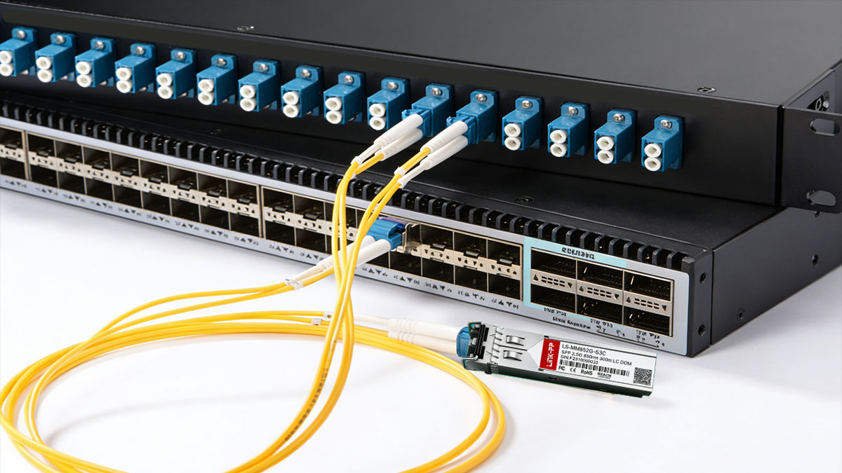
▶ Connector Types
LC Duplex
Most SR SFP and SFP+ modules use a duplex LC optical connector.
The LC interface provides:
Compact form factor suitable for high port density switches
Separate transmit (Tx) and receive (Rx) fibers
Low insertion loss when properly terminated
Deployment Notes
Ensure polarity (A-B) is correct during patching.
Use high-quality factory-terminated patch cords for consistent performance.
Regular inspection and cleaning of LC ferrules is essential to prevent optical loss and reflection issues.
▶ Link Budget Considerations
Proper link budget planning ensures that total channel loss does not exceed the optical power margin supported by the SR transceiver.
Typical Insertion Loss
Common contributors include:
Fiber attenuation (multimode fiber at 850 nm typically exhibits low loss over short distances)
Connector loss (each LC mated pair commonly introduces measurable insertion loss)
Patch panels or cross-connects
In short-reach data center environments, the cumulative channel loss is usually modest but must still be verified during design.
Margin Planning
Maintain a reserve optical margin to accommodate aging, temperature variation, and future adds/moves/changes.
Avoid designing links at the absolute maximum supported distance.
Validate actual link loss during commissioning using power meter or OTDR testing when possible.
Best Practice
A conservative design approach—high-grade MMF, minimal connector count, and verified cleanliness—significantly reduces packet errors, DOM alarms, and long-term maintenance overhead for SR SFP deployments.
⏩ SR-SFP Compatibility with Major Switch Vendors
Interoperability is one of the most important procurement and deployment considerations for SR SFP/SFP+ modules. While the optical standard (e.g., 1000BASE-SX or 10GBASE-SR) defines signaling, each switch vendor may implement validation checks that affect whether a third-party transceiver is accepted and fully supported.
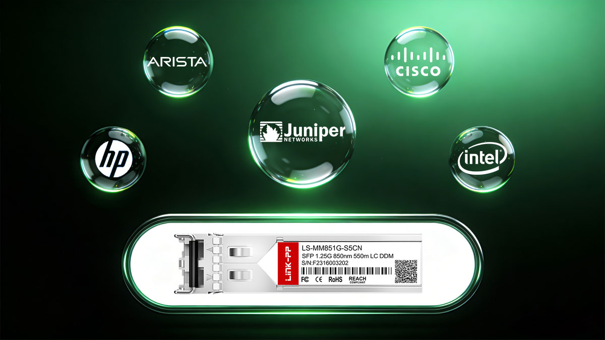
Cisco, Arista, Juniper, HPE Support
Most enterprise and data center platforms from Cisco, Arista, Juniper, and HPE support standards-compliant SR optics, but the level of acceptance for third-party modules varies:
Cisco
Many platforms validate the module identity through EEPROM fields.
Some systems allow third-party optics but may display warnings or limit official TAC support.
Certain operating modes or commands can permit operation with non-OEM coded modules.
Arista
Generally more tolerant of standards-compliant third-party transceivers.
Often operates normally if the module EEPROM is properly coded for Arista compatibility.
Juniper
Typically supports both OEM and qualified third-party optics.
May generate log notifications if the module is not vendor-coded.
HPE (Aruba Networking)
Many enterprise switches accept qualified compatible optics.
Warranty and support policies may recommend approved or tested modules.
Procurement Insight
Verify the exact switch model and OS version before purchase.
Check the vendor’s transceiver compatibility matrix to avoid deployment delays.
SFP Modules EEPROM Coding and Qualification
Each SFP/SFP+ module contains an onboard EEPROM (per SFF-8472/SFF-8431 structures) that stores identification and capability data, including:
Vendor name and OUI
Part number and revision
Supported data rates
DOM/DDM capability flags
Why Coding Matters
Switch firmware reads these fields during initialization.
Vendor-specific coding ensures the module is recognized as an approved optic.
Professionally qualified third-party suppliers often provide multi-vendor programmable coding matched to the target platform.
Best Practice
Request compatibility coding at the time of order (e.g., Cisco-coded, Arista-coded).
Maintain consistent coding across large deployments to simplify inventory and troubleshooting.
Avoiding “Unsupported Transceiver” Errors
“Unsupported transceiver” or similar alarms typically occur when the switch detects a non-approved EEPROM profile.
Common Causes
Incorrect or generic EEPROM coding
Firmware policies that enforce vendor validation
Mixed optics from different sources with inconsistent identifiers
Mitigation Steps
Confirm the required coding before installation.
Test a sample module in the target switch prior to bulk rollout.
Keep firmware versions documented—some updates tighten validation behavior.
Work with suppliers that provide pre-shipment compatibility verification and RMA support.
Operational Recommendation
In large-scale deployments, performing a short interoperability validation (lab test + DOM reading verification + link stability check) significantly reduces the risk of field failures or procurement delays.
⏩ Typical Deployment Scenarios of SR SFP Modules
SR SFP modules are optimized for short-range multimode links, making them essential in modern enterprise networks and data centers. They combine low power consumption, cost efficiency, and compact form factor, ideal for high-density deployments where distances rarely exceed a few hundred meters. The following are the most common deployment scenarios for SR SFP and SFP+ modules.
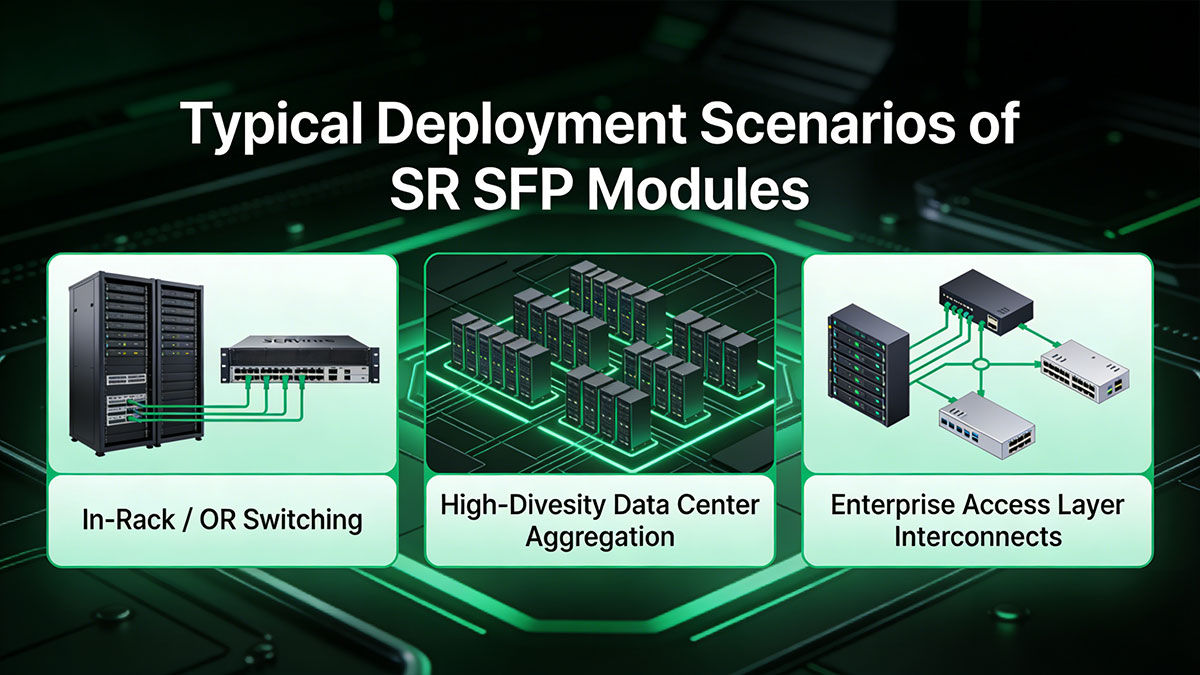
1. In-Rack / ToR Switching
Use Case: Short connections between servers and Top-of-Rack (ToR) switches within a single rack.
Typical Distance: <100 m
Fiber Type: OM3 / OM4 multimode fiber
Advantages:
Minimal insertion loss and latency
Cost-effective for high-port-count racks
Seamless integration with existing MMF infrastructure
Notes: Often used in 1G or 10G links, SR modules efficiently handle high-throughput traffic in dense rack deployments.
2. High-Density Data Center Aggregation
Use Case: Aggregating multiple ToR or leaf switches into spine switches within the same data hall.
Typical Distance: 100–300 m
Fiber Type: OM3 / OM4 multimode fiber
Advantages:
Supports high-port-count aggregation
Maintains low latency for east–west traffic
Efficient power consumption for high-density environments
Notes: SR SFP+ modules are preferred when cost-sensitive aggregation is required without the need for single-mode links.
3. Enterprise Access Layer Interconnects
Use Case: Connecting access switches to distribution or core layers in campus networks.
Typical Distance: 300–400 m (depending on fiber grade)
Fiber Type: OM3 / OM4 multimode fiber
Advantages:
Supports typical campus backbone distances
Low operational cost for short-range enterprise links
Easy to deploy and maintain
Notes: SR optics provide a reliable solution for enterprise interconnects where single-mode fiber deployment is unnecessary.
SR SFP Module Deployment Scenarios Table
Deployment Scenario | Environment | Typical Distance | Recommended Module | Reasoning / Advantages |
|---|---|---|---|---|
In-Rack / ToR Switching | Short connections within the same rack | <100 m | Low cost, minimal power, ideal for high-density racks and top-of-rack links | |
High-Density Data Center Aggregation | Multiple racks connected within a data hall | 100–300 m | 10GBASE-SR SFP+ | Supports multimode fiber, cost-efficient, commonly used for spine/leaf aggregation |
Enterprise Access Layer Interconnects | Building-to-building or short campus links | 300–550 m | 10GBASE-SR SFP+ or 1000BASE-SX SFP | Compatible with OM3/OM4 MMF, maintains link margin, flexible deployment in enterprise networks |
⏩ SR SFP Module Power and Thermal Profile
SR SFP modules are designed for low-power, short-distance multimode applications, making them ideal for high-density data center deployments. Understanding their power consumption and thermal characteristics is critical for ensuring network reliability and proper chassis cooling.
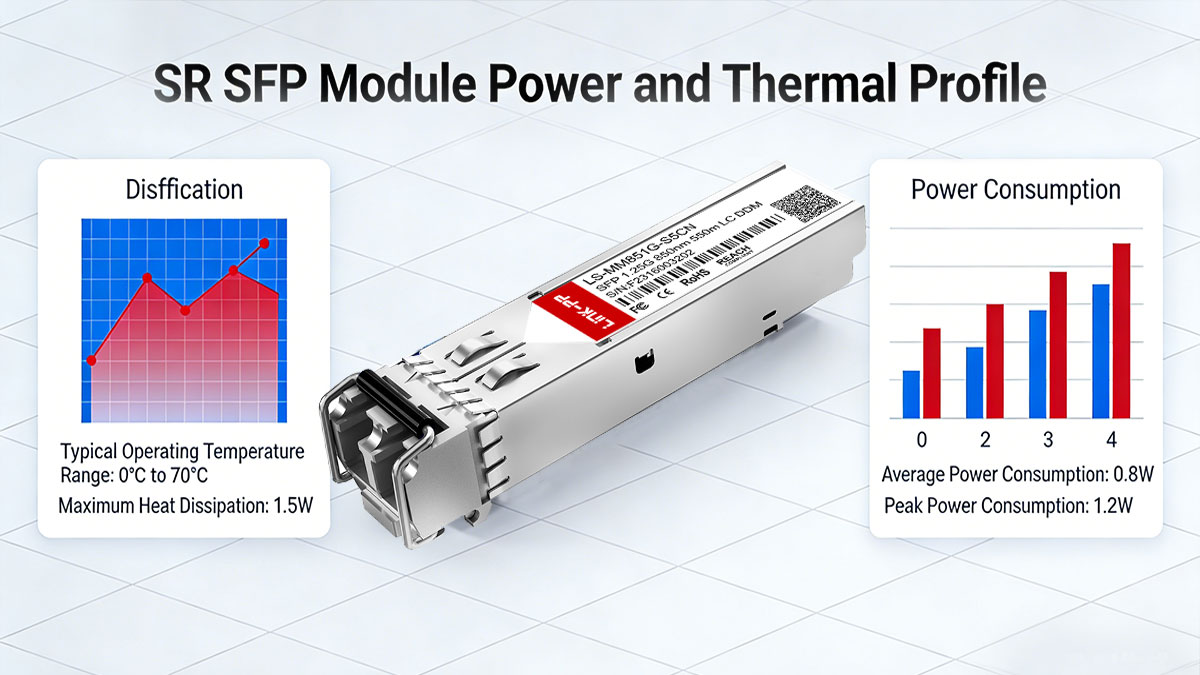
Typical Power Consumption Range
Module Type | Typical Power Consumption | Notes |
|---|---|---|
1000BASE-SX SFP | 0.8–1.0 W | Standard Gigabit short-range multimode transceiver |
10GBASE-SR SFP+ | 1.0–1.5 W | High-volume deployment in ToR and aggregation links |
Power varies slightly by manufacturer and DDM/DOM support.
Lower power helps reduce total cooling requirements and operating costs.
High-Density Switch Implications
When deploying dozens or hundreds of SR SFP/SFP+ modules in a single chassis, cumulative power draw can affect switch thermal profiles.
Ensure proper airflow (front-to-back or back-to-front) according to switch specifications.
DOM monitoring can help track module temperature and detect hotspots early, preventing throttling or link failures.
Planning for per-slot and total chassis power is essential when scaling high-density racks with multiple SR SFP modules.
⏩ How to Select the Right SR SFP Module
Selecting the optimal SR SFP module requires balancing distance requirements, fiber type, vendor compatibility, and power/thermal considerations. Following a structured checklist ensures reliable deployment and simplifies procurement decisions.
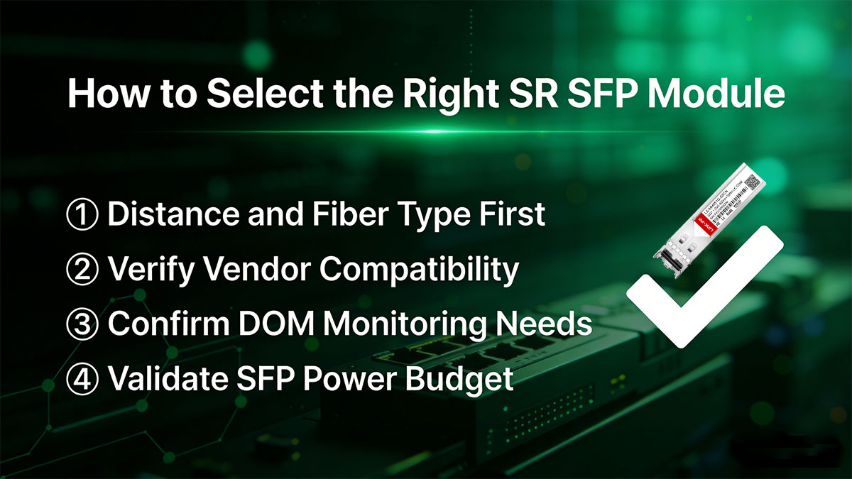
① Distance and Fiber Type First
Determine the required link distance: typical SR SFP ranges up to 300 m on OM3 and 400 m on OM4 multimode fiber.
Choose fiber grade (OM2/OM3/OM4) to match the planned distance and bandwidth requirements.
For shorter links (<100 m), lower-grade fiber or passive DAC alternatives may be sufficient.
② Verify Vendor Compatibility
Confirm module support for your switch vendor: Cisco, Arista, Juniper, HPE, etc.
Check EEPROM coding and qualification to avoid “unsupported transceiver” errors.
Prefer modules with multi-vendor validation if your network mixes brands.
③ Confirm DOM Monitoring Needs
Determine whether DOM/DDM support is required for real-time monitoring of optical power, temperature, and laser bias current.
Essential in high-density data centers to prevent undetected link degradation.
Modules without DOM may be sufficient for short, low-criticality links.
④ Validate SFPs Power Budget
Check per-port power consumption (typically 0.8–1.5 W) and ensure the chassis or switch has adequate thermal headroom.
High-density deployments require planning cumulative power and airflow.
Consider low-power variants for energy efficiency and reduced cooling costs.
⑤ SR SFP Module Decision Checklist Table
Selection Factor | Recommendation / Threshold | Notes / Considerations |
|---|---|---|
Link Distance | ≤ 300 m on OM3, ≤ 400 m on OM4 | Verify actual fiber grade and deployment distance; allow margin for patch cords |
Fiber Type | OM2 / OM3 / OM4 multimode | OM3/OM4 preferred for high-bandwidth ToR / aggregation links |
Vendor Compatibility | Cisco, Arista, Juniper, HPE verified | Check EEPROM coding to avoid “unsupported transceiver” errors; multi-vendor support recommended |
DOM / DDM Support | Required for monitoring-critical links | Provides real-time Tx/Rx power, temperature, and laser bias current; optional for short, non-critical links |
Power Consumption | Typical 0.8–1.5 W per port | Confirm switch/chassis thermal headroom; consider low-power options for dense racks |
Deployment Scenario | Data center ToR, aggregation, campus links | Choose based on link distance, fiber type, and monitoring needs |
Cost / Procurement Notes | SR SFP usually high-volume, low cost | OEM vs compatible modules, stock availability, and lead time affect procurement decisions |
⏩ SR SFP Module FAQs
Q1: What does SR mean in SFP?
A: SR stands for Short-Range. SR SFP modules are designed for multimode fiber links, typically operating at 850 nm using VCSEL lasers for short-distance data transmission.
Q2: What distance does SR support?
A: SR modules typically support distances up to ~300 meters on OM3 and ~400 meters on OM4 multimode fiber, depending on the standard (1000BASE-SX or 10GBASE-SR).
Q3: Can SR run over single-mode fiber?
A: No. SR SFPs are optimized for multimode fiber (MMF). Using them over single-mode fiber (SMF) may cause signal loss and performance issues.
Q4: Is SR cheaper than LR?
A: Yes. SR modules generally have lower cost per link than LR (Long-Range) modules, mainly because multimode fiber transceivers require less precise optics and lower power consumption.
Q5: Are third-party SR modules reliable?
A: High-quality third-party SR modules can be reliable if they comply with IEEE standards and include proper EEPROM coding for vendor compatibility. However, always verify supplier credentials and test before mass deployment.
Q6: Do SR modules support DOM?
A: Yes. Most SR SFP and SFP+ modules support DOM (Digital Optical Monitoring), allowing real-time monitoring of optical power, temperature, and supply voltage.
Q7: Can SR and DAC coexist on the same switch?
A: Yes. Many switches allow simultaneous use of SR SFPs and DAC cables. Ensure that port configuration, speed, and lane mapping are compatible to avoid link errors.
⏩ Implementation Best Practices and SR Modules Further Resources
Interoperability Testing
Perform cross-vendor testing to ensure SR SFP module work reliably with your switches, DACs, or AOCs. Validate link stability under load and check for unsupported transceiver messages.
Optical Power Verification
Measure Tx/Rx power and link margin to confirm compliance with IEEE 802.3 standards. Ensure insertion loss and distance do not exceed the SR module’s specifications.
Labeling and Asset Management
Use clear labeling for each module, fiber, and patch panel port. Maintain an inventory record for easier maintenance, replacement, and network troubleshooting.
Further Resources and Compatibility Tools
Datasheets: Detailed specifications for each SR SFP variant.
Compatibility Matrix: Cross-check vendor switches and module support.
SR/LR Selection Guide: Quick reference for choosing appropriate optics.
Request Compatibility Check: Submit module and switch info for verification by vendor support or product experts.
💡 Explore and purchase verified SR SFP modules at the LINK-PP Official Store for reliable, high-performance short-reach connectivity.


