


In today’s high-speed Ethernet environment, maintaining signal integrity is no longer optional—it’s a design requirement. Whether you’re developing industrial networking hardware, medical diagnostic devices, or telecom-grade switches, one physical-layer metric must not be overlooked: Insertion Loss.
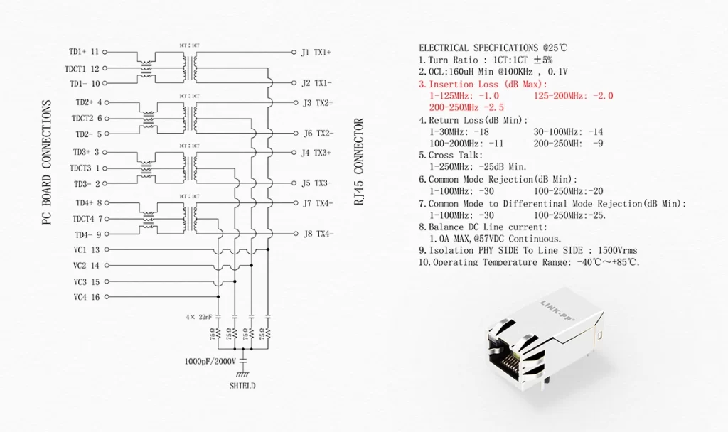
For RJ45 MagJack connectors—RJ45 jacks with integrated magnetics—insertion loss directly affects how effectively data travels across the link. Understanding this parameter is essential for engineers striving for standards compliance and long-term system stability.
Key Takeaways
Insertion Loss = signal loss through the connector, measured in dB.
Lower is better:Less than -1.0 dB is ideal for Gigabit speeds.
Matters for signal integrity, Ethernet stability, IEEE compliance.
Influenced by: transformer design, plating, shielding, PCB layout.
LINK-PP RJ45 connectors tested across 1G / 2.5G / 5G speeds with reliable IL performance.
Ideal for: medical devices, industrial networks, telecom systems.
Engineered for performance: LINK-PP offers RoHS-compliant, low-loss, high-reliability MagJack solutions.
✅ Fast delivery & in-stock inventory available.
Insertion Loss Testing
What Is Insertion Loss?
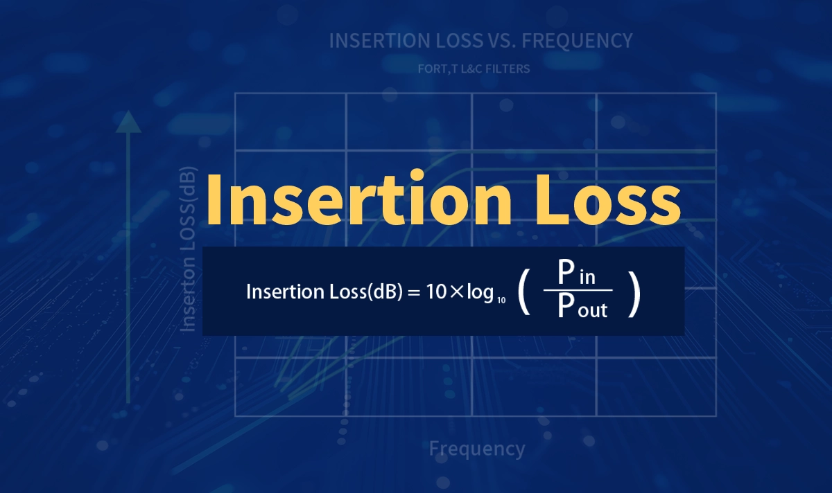
Insertion Loss (IL) is defined as the attenuation of signal power caused by inserting a component (like an RJ45 connector) into a signal path. It is expressed in decibels (dB) and increases with frequency.
A lower insertion loss value indicates better performance.
Ideal connectors should maintain minimal signal degradation across the full operating bandwidth.
📐 Equation:

Where:
PinP_{in}Pin = input signal power
PoutP_{out}Pout = output signal power after passing through the RJ45 Magnetic connector
Why IL Matters in Ethernet Applications
As Ethernet speeds scale from 10/100 Mbps to 2.5G, 5G, and even 10G, Magjacks must perform consistently across wider frequency spectrums. Poor insertion loss can cause:
Higher bit error rates (BER)
Packet loss or retransmissions
Reduced cable reach
Inability to pass IEEE 802.3 compliance tests
Insertion loss is especially critical in applications like:
Medical devices (patient monitors, imaging systems)
Industrial controllers
Telecom routers & switches
PoE+ powered devices (e.g. security cameras, access points)
What Affects Insertion Loss in RJ45 MagJacks?
Impact on Insertion Loss | |
|---|---|
Internal transformer design | Impacts core losses and impedance control |
Pin layout and PCB routing | Longer paths = higher resistive and dielectric losses |
Contact plating | High-quality gold minimizes resistance at contact points |
Shielding structure | Affects EMI rejection and signal containment |
Core material in magnetics | Determines performance at high frequencies |
LINK-PP RJ45 Connector Insertion Loss Comparison
Model | Ethernet Speed | Insertion Loss | Frequency Range |
|---|---|---|---|
10/100BASE-TX | -1.0 dB Max | 1–65 MHz | |
1000BASE-T | -1.0 dB Max | 1–100 MHz | |
2.5GBASE-T | -0.5 dB Max (1–50 MHz), -1.0 dB Max (50–125 MHz) | 1–125 MHz | |
5GBASE-T | -1.0 dB Max (1–125 MHz), -2.0 dB Max (125–200 MHz), -2.5 dB (200–250 MHz) | 1–250 MHz |
Design Recommendations for Engineers
To minimize insertion loss in your Ethernet designs:
Choose connectors with consistent IL performance across your operating frequency
Follow recommended PCB layout guidelines (avoid long trace routing from the jack)
Use matched impedance and shielded connectors to reduce reflection and common-mode noise
Select suppliers with complete test data across frequency ranges and compliance history
💡 LINK-PP provides detailed insertion loss test reports, RoHS certificates, and IEEE 802.3 compliance for every production batch.
Insertion Loss Testing
How to Test Insertion Loss
Technicians use several steps and tools for insertion loss testing in copper networks. The process starts with selecting a cable tester that meets industry standards. Devices like the Fluke Networks DSX CableAnalyzer series can automatically test each cable pair across all required frequencies. The testing procedure involves connecting the tester to both ends of the cable, running the test, and reviewing results for attenuation or insertion loss, connector return loss, and other parameters. The insertion loss formula for copper uses voltage measurements:
IL = -20 log10 (Vt/Vr)
This formula helps measure attenuation by comparing the voltage at the transmitter and receiver ends. Regular testing ensures cables meet standards and helps identify faults that cause attenuation or insertion loss.
Testing Methods for Copper
Copper cable testing uses different tester types. Verification testers check basic connections, qualification testers assess if cables support certain technologies, and certification testers verify compliance with ISO and TIA standards. Certification testers, such as the DSX CableAnalyzer, provide detailed diagnostics for attenuation, insertion loss, and connector return loss. These testers measure attenuation at each frequency, plot results, and quickly identify faults. The testing procedure follows strict accuracy rules, like Level V accuracy, and uses automatic frequency sweeps. The table below shows key aspects of copper insertion loss testing:
Aspect | Details |
|---|---|
Tester Accuracy | Level V, standards-based |
Recommended Tester | DSX CableAnalyzer series |
Testing Method | Automatic, frequency-based, diagnostic features |
Key Rules | 3 dB rule, 4 dB rule for crosstalk |
Tip: Regular insertion loss testing and connector return loss testing help maintain network reliability.
Insertion Loss in Optical Fiber
Insertion loss in optical fiber uses a different testing procedure. Technicians use Optical Loss Test Sets (OLTS) and Optical Time Domain Reflectometers (OTDR) to measure attenuation or insertion loss. The insertion loss formula for fiber is:
A = 10 log10(Pin / Pout)
Pin is the input optical power, and Pout is the output. For example, if Pin is 10 mW and Pout is 5 mW, the loss is 3 dB. OLTS measures total attenuation or insertion loss, while OTDR locates faults and measures connector return loss along the fiber. Unlike copper, fiber testing measures light power, not voltage. Both copper and fiber require regular insertion loss testing to ensure performance, but the tools and methods differ due to the physical properties of each medium.
Conclusion
Insertion loss plays a defining role in Ethernet connector performance. As bandwidth demands continue to grow, so does the need for RJ45 connectors engineered for signal clarity and system compliance.
With decades of manufacturing experience and over 6 million parts shipped monthly, LINK-PP delivers:
Precision-engineered MagJack RJ45 connectors
Consistent insertion loss performance across frequency
Compliance with IEEE 802.3, RoHS, and REACH standards
Fast global shipping and in-stock inventory for standard models


