


In today’s high-speed networking environments, SFP distance has become one of the most critical yet commonly misunderstood factors when designing fiber optic connections. Whether deploying enterprise switches, telecom backbones, or data center links, engineers often assume that speed (1G, 2.5G, or 10G) determines how far a connection can reach. In reality, SFP transmission distance is defined by optical design—not data rate.
An SFP (Small Form-factor Pluggable) module transmits data over fiber using specific wavelengths and power levels, which directly influence how far the signal can travel before degradation occurs. This is why two modules with the same form factor can have dramatically different ranges—some limited to a few hundred meters, while others reliably reach tens of kilometers.
A frequent source of confusion comes from real-world deployment experiences shared across engineering communities. Many network failures are not caused by switch incompatibility or bandwidth limits, but by incorrect assumptions about SFP range, wavelength selection, or fiber type mismatch (single-mode vs. multimode). For example, using short-range optics (850nm SR) on long fiber runs or mismatching long-range modules on short patch links can lead to unstable connections, signal overload, or complete link failure.
This makes understanding SFP distance essential not only for network design but also for cost efficiency and reliability. Choosing the right optical module requires evaluating multiple factors, including fiber type, wavelength (850nm vs. 1310nm), link budget, and real installation conditions, rather than relying solely on datasheet specifications.
In this guide, we will break down what SFP distance really means, how it is determined, why real-world performance often differs from theoretical values, and how to correctly select an SFP module for stable and scalable network deployment.
🟢 What Is SFP Distance in Fiber Optic Networks?
Definition of SFP Transmission Distance
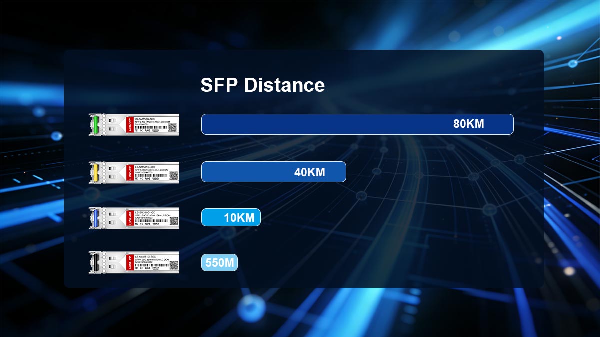
SFP distance refers to the maximum effective range over which an SFP optical module can transmit data while maintaining signal integrity. It is typically measured in kilometers (km) for fiber optic links or meters for short-range multimode connections.
This distance is not a fixed property of the SFP slot or switch. Instead, it is a specification defined by the optical transceiver itself, indicating how far the optical signal can travel before it becomes too weak (attenuated) or distorted to be reliably received.
In practical terms, SFP distance represents the usable transmission reach under standardized laboratory conditions, assuming correct fiber type, clean connectors, and compliant optical power levels.
Why Distance Depends on Optics, Not Port Speed
A common misconception in networking is that higher data rates automatically mean shorter transmission distances. In reality, SFP distance is determined by the optical characteristics of the transceiver, not the Ethernet speed.
The key factors that define distance include:
Optical wavelength (e.g., 850nm, 1310nm, 1550nm)
Transmitter output power
Receiver sensitivity
Fiber attenuation rate (loss per km)
Connector and splice loss
For example:
An 850nm SR module is optimized for multimode fiber and short-range transmission.
A 1310nm LR module is designed for single-mode fiber and significantly longer distances.
Even if both modules operate at different speeds (1G, 2.5G, or 10G), their distance limitations remain fundamentally tied to optical physics—not bandwidth.
This is why a 2.5G SFP module can sometimes achieve the same reach as a 1G SFP module, provided the optical design (wavelength and power budget) is equivalent.
SFP vs. SFP+ vs. 2.5G SFP Relationship
SFP Type | Standard | Typical Distance Range |
|---|---|---|
SFP (1G Ethernet) | 1000BASE-SX / LX / ZX | SR: up to ~550m (MMF) |
SFP+ (10G Ethernet) | 10GBASE-SR / LR / ER | SR: ~300–400m (MMF) |
2.5G SFP (2.5GbE) | 2.5GBASE variants | SR-type: hundreds of meters (MMF) |
Key Insight: The “SFP class” (SFP, SFP+, 2.5G SFP) defines speed capability, while actual transmission distance is determined by optical design (SR, LR, ER) and fiber type (MMF vs. SMF).
Technical Baseline Explanation
From an engineering perspective, SFP distance is governed by optical link budget theory, which ensures that:
The transmitted optical power (TX) minus all losses (fiber attenuation + connectors + splices) must still be higher than the receiver sensitivity threshold.
This principle ensures signal reliability across different deployment environments.
A simplified representation:
Available Power Budget = TX Power − RX Sensitivity
Total Link Loss = Fiber Loss + Connector Loss + Safety Margin
If the total link loss exceeds the available power budget, the connection will fail or become unstable—even if the fiber physically spans a shorter distance than the module’s rated specification.
This is why experienced network engineers never rely solely on distance labels. Instead, they validate:
Fiber type compatibility (SMF vs. MMF)
Wavelength alignment
Power budget margin (typically 3–5 dB safety buffer)
By applying these principles, SFP distance becomes not just a specification—but a predictable engineering outcome based on optical physics and system design.
🟢 SFP Distance Ranges by Optical Type (SR, LR, ER, ZR)
SFP distance is primarily determined by the optical transceiver type, not the device or Ethernet speed. Each optical class—SR, LR, ER, and ZR—follows different physical design standards that define how far a signal can reliably travel over fiber.
Understanding these categories is essential because real-world network performance depends on selecting the correct optic for the required transmission distance and fiber infrastructure.
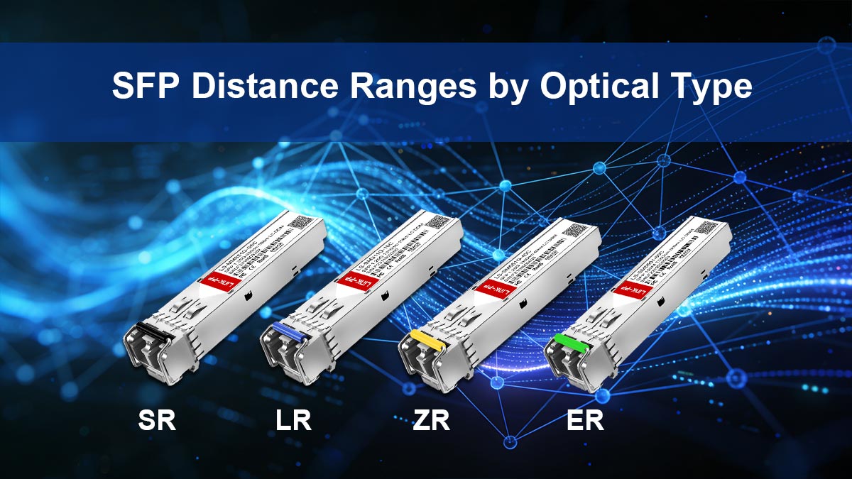
1000BASE-SX / SR (Short-Range Multimode)
SR (Short Range) or SX optics are designed for short-distance transmission over multimode fiber (MMF) using an 850nm wavelength.
Typical characteristics:
Wavelength: 850nm (VCSEL laser)
Fiber type: Multimode (OM1 / OM2 / OM3 / OM4)
Common distance range:
~275m (OM1)
~550m (OM3/OM4 optimized conditions)
Use cases:
Data centers (rack-to-rack connections)
Enterprise LAN backbone within a building
High-density short-range switching
Key limitation: SR optics are highly sensitive to fiber quality and modal dispersion, meaning performance drops significantly if older or lower-grade multimode fiber is used.
1000BASE-LX / LR (Long-Range Single-Mode)
LR (Long Range) optics are the most commonly used SFP type for enterprise and ISP deployments requiring longer reach.
Typical characteristics:
Wavelength: 1310nm
Fiber type: Single-mode fiber (OS1 / OS2)
Standard distance:
Up to ~10 km (1G and 2.5G variants)
Sometimes shorter in mixed or non-ideal conditions
Use cases:
Campus networks
Enterprise building interconnects
ISP access networks
Key advantage: Single-mode fiber significantly reduces signal dispersion, enabling stable long-distance transmission with lower attenuation compared to multimode systems.
Extended Range Optics (ER / ZR)
For long-haul communication, ER (Extended Range) and ZR (Zettabyte Range) optics are used in high-performance backbone infrastructure.
Typical characteristics:
Wavelength: 1550nm (common for long-haul transmission)
Fiber type: Single-mode (high-grade OS2)
Distance range:
ER: ~40 km
ZR: ~80 km or more (depending on system design)
Use cases:
Telecom backbone networks
Inter-city or metro ring networks
Large-scale ISP infrastructure
Data center interconnect (DCI)
Key consideration: These optics often require stricter optical power budget control, including attenuation planning to avoid receiver overload on shorter-than-expected links.
Practical Real-World vs. Theoretical Distance
While datasheets define theoretical maximum distances, real-world SFP performance often differs due to deployment conditions.
Theoretical (Lab Conditions)
Clean fiber with minimal loss
Ideal connectors and splicing
Standardized power levels
No environmental interference
Real-World Conditions
Fiber aging and contamination
Patch panel and connector losses
Improper cable bending radius
Mixed fiber types or legacy infrastructure
Variations in transceiver manufacturing tolerances
As a result:
A “10 km LR module” may perform reliably at only 6–8 km in poor installations
A short-range SR link may fail below rated distance if fiber quality is degraded
SFP distance ratings are engineering benchmarks, not guarantees. Successful deployment depends on matching:
Optical type (SR / LR / ER / ZR)
Fiber infrastructure quality
Link budget margin
Environmental installation conditions
This is why experienced network engineers always design with a safety margin (typically 3–5 dB) instead of relying solely on manufacturer distance specifications.
🟢 850nm vs. 1310nm SFP: How Wavelength Impacts Distance
Wavelength is one of the most important factors that determines SFP distance performance. Even when two modules share the same speed (1G, 2.5G, or 10G), the choice between 850nm and 1310nm optics fundamentally changes how far the signal can travel and how stable the link will be in real deployments.
Understanding this distinction is critical for avoiding link failure, instability, or unnecessary cost in fiber network design.
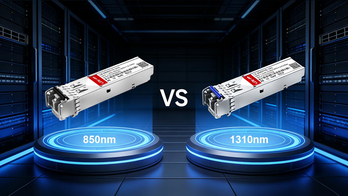
850nm (Multimode, VCSEL-Based, Short Reach)
850nm SFP modules are designed for short-range communication over multimode fiber (MMF) using VCSEL (Vertical-Cavity Surface-Emitting Laser) technology.
Key characteristics:
Wavelength: 850nm
Fiber type: Multimode (OM1 / OM2 / OM3 / OM4)
Transmission range:
Typically up to ~300m–550m depending on fiber grade
Optimized for:
Short-distance, high-density environments
Common use cases:
Data center rack-to-rack connections
Enterprise LAN switches within the same building
High-speed server access links
Key limitation: Multimode fiber causes modal dispersion, where light signals travel in multiple paths, leading to signal spreading over distance. This limits how far 850nm optics can reliably operate.
1310nm (Single-Mode, Long Reach, Stable Transmission)
1310nm SFP modules are designed for medium to long-distance communication using single-mode fiber (SMF).
Key characteristics:
Wavelength: 1310nm
Fiber type: Single-mode (OS1 / OS2)
Transmission range:
Commonly up to ~10 km (standard LR optics)
Can extend further with ER/ZR variants
Optimized for:
Stable long-distance communication
Common use cases:
Campus interconnects
Metropolitan networks
ISP access networks
Inter-building links
Key advantage: Single-mode fiber allows light to travel in a single path, significantly reducing dispersion and enabling much longer and more stable transmission distances compared to multimode systems.
Why Wavelength Determines Attenuation Behavior
The impact of wavelength on SFP distance is directly tied to how light behaves in fiber optics.
Key physical principles:
Attenuation loss varies by wavelength
850nm: higher attenuation in fiber over distance
1310nm: lower attenuation, better long-distance performance
Fiber interaction differences
Multimode fiber is optimized for shorter wavelengths (850nm)
Single-mode fiber is optimized for longer wavelengths (1310nm / 1550nm)
Signal dispersion behavior
850nm: higher modal dispersion → limits distance
1310nm: minimal dispersion → supports longer reach
In simple terms: 850nm is optimized for speed over short distances, while 1310nm is optimized for stability over long distances.
Common Deployment Mistakes Users Make
Despite clear technical standards, wavelength-related deployment errors are among the most common causes of SFP link failure.
❌ Mistake 1: Using 850nm optics on single-mode fiber
Often assumed to be interchangeable
Result: weak or no signal due to fiber mismatch
❌ Mistake 2: Using 1310nm optics for short multimode links
May work in some cases but is not optimized
Can cause inefficient performance or instability
❌ Mistake 3: Ignoring fiber type entirely
Users focus on “2.5G or 10G” but ignore MMF vs SMF
Leads to unexpected link failure
❌ Mistake 4: Assuming wavelength does not affect distance
Common misconception among beginners
Leads to wrong module selection and troubleshooting delays
The choice between 850nm and 1310nm SFP modules is not just a technical specification—it directly determines whether a link is physically capable of reaching the required distance.
For reliable deployment:
Use 850nm (SR) for short-range multimode environments
Use 1310nm (LR) for stable long-distance single-mode networks
Always match wavelength with fiber type and expected link budget
This alignment is essential for achieving predictable SFP distance performance in real-world networks.
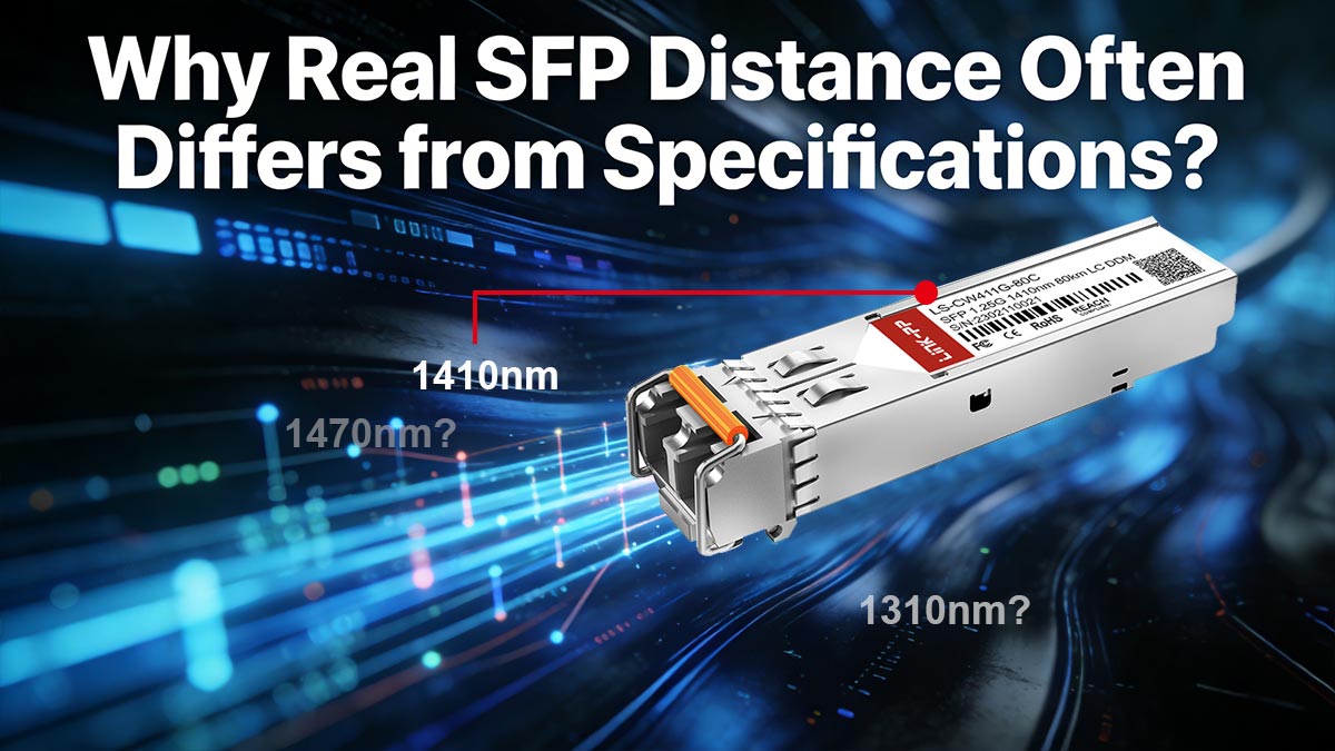
🟢 Why Real SFP Distance Often Differs from Specifications
Although SFP modules are labeled with clear distance ratings such as 550m, 10km, or 40km, real-world deployments often show noticeably different results. In practice, actual SFP distance is influenced by environmental, physical, and engineering variables that are not fully reflected in datasheet specifications.
Understanding these gaps is essential for preventing link instability, unexpected failures, and over-designed or under-performing fiber networks.
1. Fiber Quality and Insertion Loss
One of the most significant factors affecting real SFP distance is fiber quality.
Even if the fiber type (single-mode or multimode) is correct, performance can vary due to:
Aging or degraded fiber infrastructure
Poor manufacturing quality in low-grade cables
Excessive bending or physical stress on fiber runs
Splice points introducing additional loss
Each of these contributes to insertion loss, which reduces optical signal strength as it travels along the link.
Key impact: Higher insertion loss reduces usable transmission distance, even if the SFP module is rated for long-range operation.
2. Connector Contamination and Attenuation
In real deployments, fiber connectors are one of the most common sources of performance degradation.
Dust, oil, or microscopic debris on LC/SC connectors can cause:
Increased signal reflection (backscatter)
Unexpected attenuation spikes
Intermittent or unstable link performance
Even a small amount of contamination can significantly reduce optical power efficiency.
Industry insight: Experienced network engineers often consider connector cleanliness as a primary troubleshooting step before replacing any hardware.
3. Link Budget Miscalculation
A major cause of SFP distance failure is incorrect link budget planning.
A proper link budget must account for:
Transceiver TX power
Receiver sensitivity
Fiber attenuation per kilometer
Connector and splice losses
Safety margin (typically 3–5 dB)
However, in real-world deployments, users often:
Ignore total system loss
Assume maximum rated distance equals guaranteed performance
Fail to include patch panel or splice losses
Result: Even a “10 km SFP module” may fail at 6–8 km if the total optical loss exceeds the available power budget.
4. Transceiver Power Mismatch Issues
Another common issue is optical power imbalance between transmitter and receiver.
Problems include:
TX power too high → receiver overload (especially in short links)
TX power too low → signal cannot reach receiver threshold
Mixing non-matched OEM or third-party modules
This is especially important in modern deployments using:
Mixed vendor switches
Industrial SFP environments
Long and short link combinations in the same network
Key insight: SFP distance is not only about reaching far enough—it is also about not exceeding safe optical power levels.
5. Real-World vs Datasheet Performance Gap
Datasheet specifications are based on controlled laboratory conditions, including:
Perfect fiber alignment
Ideal connector quality
Standardized environmental conditions
No aging or physical stress factors
In contrast, real-world deployments include:
Infrastructure variability
Installation imperfections
Environmental temperature fluctuations
Aging network components
As a result:
Rated distances are maximum theoretical benchmarks
Real-world stable performance is often 10–30% lower depending on conditions
The difference between theoretical and real SFP distance is not a product flaw—it is a result of system-level optical behavior in non-ideal environments.
For reliable deployment, engineers should:
Always calculate a proper link budget
Maintain clean and properly terminated fiber connections
Use appropriate safety margins
Validate compatibility between transceiver power levels and fiber type
Ultimately, real SFP distance is determined by system design quality—not just module specifications.
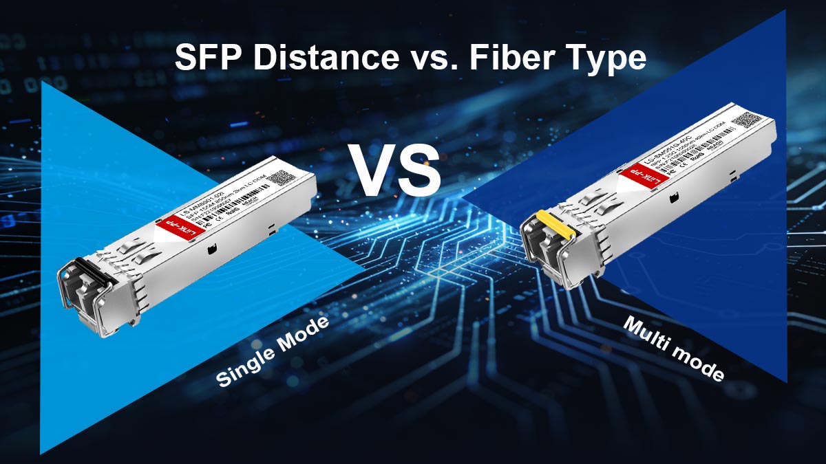
🟢 SFP Distance vs. Fiber Type (Single Mode vs. Multimode)
SFP distance is not only defined by the optical module (SR, LR, ER), but also heavily depends on the fiber type used in the network infrastructure. Choosing between multimode fiber (MMF) and single-mode fiber (SMF) is one of the most important decisions in determining achievable transmission distance, cost efficiency, and long-term scalability.
OM1 / OM2 / OM3 / OM4 Multimode Limitations
Multimode fiber (MMF) is designed for short-distance, high-speed transmission within confined environments such as data centers and enterprise buildings. It supports multiple light paths (modes), which makes it easier to couple light but introduces distance limitations due to dispersion.
Common multimode types:
OM1 (62.5/125 μm)
Legacy fiber type
Very limited distance for modern speeds
Typically unsuitable for 2.5G/10G modern deployments
OM2 (50/125 μm)
Slightly improved over OM1
Still limited range for higher-speed applications
OM3 (laser-optimized 50/125 μm)
Common in modern data centers
Supports higher speeds like 10G/25G over moderate distances
OM4 (enhanced OM3)
Best multimode performance
Longer reach within data centers (but still limited vs single-mode)
Key limitation: Even with high-quality OM4 fiber, multimode systems are still inherently distance-limited due to modal dispersion.
OS1 / OS2 Single-Mode Advantages
Single-mode fiber (SMF) is designed for long-distance and high-precision optical transmission, using a much smaller core that allows light to travel in a single path.
Common single-mode types:
OS1
Indoor or controlled environment SMF
Moderate attenuation performance
OS2
Outdoor / telecom-grade SMF
Lower attenuation and better long-distance performance
Key advantages:
Supports distances up to 10 km, 40 km, 80 km or more depending on optics
Minimal modal dispersion (single light path)
Lower signal degradation over distance
Better suited for scalable backbone infrastructure
Key insight: Single-mode fiber is the default choice for any network that requires stable long-distance SFP transmission.
Compatibility Between Fiber Type and SFP Module
Correct pairing between fiber type and SFP optics is essential for stable performance.
Proper matching examples:
Multimode fiber (OM3/OM4) → 850nm SR optics
Single-mode fiber (OS1/OS2) → 1310nm LR or 1550nm ER optics
Common mismatches:
SR optics on single-mode fiber → weak or no signal
LR optics on multimode fiber → unstable or non-compliant performance
Important rule: SFP distance is only valid when fiber type and optical wavelength are correctly matched.
Even if the module physically connects, incorrect pairing often results in:
Reduced transmission distance
Increased bit error rate (BER)
Unstable or intermittent link behavior
Cost vs. Distance Trade-offs in Deployment
Selecting between multimode and single-mode fiber is often a balance between budget constraints and required transmission distance.
Multimode (MMF) advantages:
Lower installation cost
Cheaper transceivers (SR optics)
Easier termination and installation
Ideal for short-range structured cabling
Single-mode (SMF) advantages:
Much longer transmission distance
Higher scalability for future upgrades
Lower long-term replacement cost
Suitable for campus, metro, and ISP networks
Trade-off consideration:
MMF is cost-effective but limited in reach
SMF has higher initial cost but significantly better scalability
Strategic insight: Many organizations choose single-mode fiber even for short distances to future-proof infrastructure and avoid re-cabling costs later.
SFP distance is not a fixed parameter—it is the result of fiber type, optical design, and system architecture working together.
For reliable network design:
Use multimode fiber for short-range, cost-sensitive deployments
Use single-mode fiber for scalable, long-distance infrastructure
Always align fiber type with SFP optical wavelength and expected link distance
This alignment ensures predictable performance and prevents the most common causes of fiber link failure in real-world deployments.
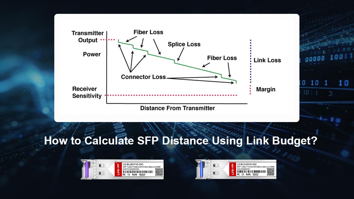
🟢 How to Calculate SFP Distance Using Link Budget
Calculating SFP distance in real deployments is not based on guesswork or datasheet labels—it is based on a fundamental engineering principle called the optical link budget. This method determines whether an SFP module can maintain a stable signal over a given fiber length by comparing transmitted power, received sensitivity, and total system losses.
TX Power vs. RX Sensitivity Explanation
Every SFP module operates within a defined optical power range:
TX Power (Transmit Power):
The amount of optical energy emitted by the SFP laser.RX Sensitivity (Receiver Sensitivity):
The minimum optical signal strength required for the receiver to correctly interpret data.
Core principle: A valid SFP link exists only when the received signal is stronger than the receiver’s minimum sensitivity threshold.
Simple relationship:
Higher TX power → longer possible distance
Better RX sensitivity → improved weak-signal detection
However, this must always be balanced to avoid:
Signal loss (too weak)
Receiver overload (too strong)
Insertion Loss Calculation Method
To estimate realistic SFP distance, engineers calculate total optical loss across the fiber link.
Total Link Loss includes:
Fiber attenuation (loss per km)
Connector loss (each LC/SC connection)
Splice loss (fusion or mechanical joints)
Patch panel loss
Simplified formula:
Total Loss = Fiber Loss + Connector Loss + Splice Loss
Then compare it with:
Available Power Budget = TX Power − RX Sensitivity
Decision rule:
If Total Loss ≤ Available Power Budget → link is stable
If Total Loss > Available Power Budget → link fails or becomes unstable
Safety Margin Recommendation (Engineering Best Practice)
In real-world deployments, engineers never design a link to operate at 100% of theoretical capacity. A safety margin (also called engineering headroom) is always included.
Recommended margin:
3–5 dB minimum safety buffer
Higher margin for:
Industrial environments
Long-distance telecom links
Aging fiber infrastructure
Why safety margin matters:
Fiber aging increases loss over time
Temperature fluctuations affect optical performance
Connectors degrade with repeated use
Dust and contamination introduce unexpected attenuation
Key insight: A link that works “on paper” may fail in real life without proper safety margin.
Simple Decision Formula for Deployment Planning
To simplify SFP distance planning, engineers often use a practical decision model:
✔ Step-by-step rule:
Identify SFP type (SR / LR / ER)
Check TX power and RX sensitivity
Calculate estimated total loss
Compare with power budget
Apply safety margin (3–5 dB)
✔ Final decision logic:
If budget > loss + margin → ✔ Safe deployment
If budget ≈ loss → ⚠ Risk of instability
If budget < loss → ❌ Link will fail
SFP distance is not a fixed number—it is the result of optical power balance across an entire system.
By using link budget calculations, engineers can:
Predict real-world SFP performance accurately
Avoid unexpected link failures
Optimize cost vs distance decisions
Ensure long-term network stability
This makes link budget analysis the most reliable method for determining true SFP distance capability in any fiber network deployment.
🟢 Common SFP Distance Problems and How to Fix Them
Even when SFP modules are correctly installed and the link appears physically connected, SFP distance-related issues are among the most common causes of instability in fiber networks. These problems are usually not caused by the switch or port itself, but by optical mismatches, fiber conditions, or incorrect module selection.
Understanding these failure patterns helps engineers quickly diagnose and restore stable connectivity.
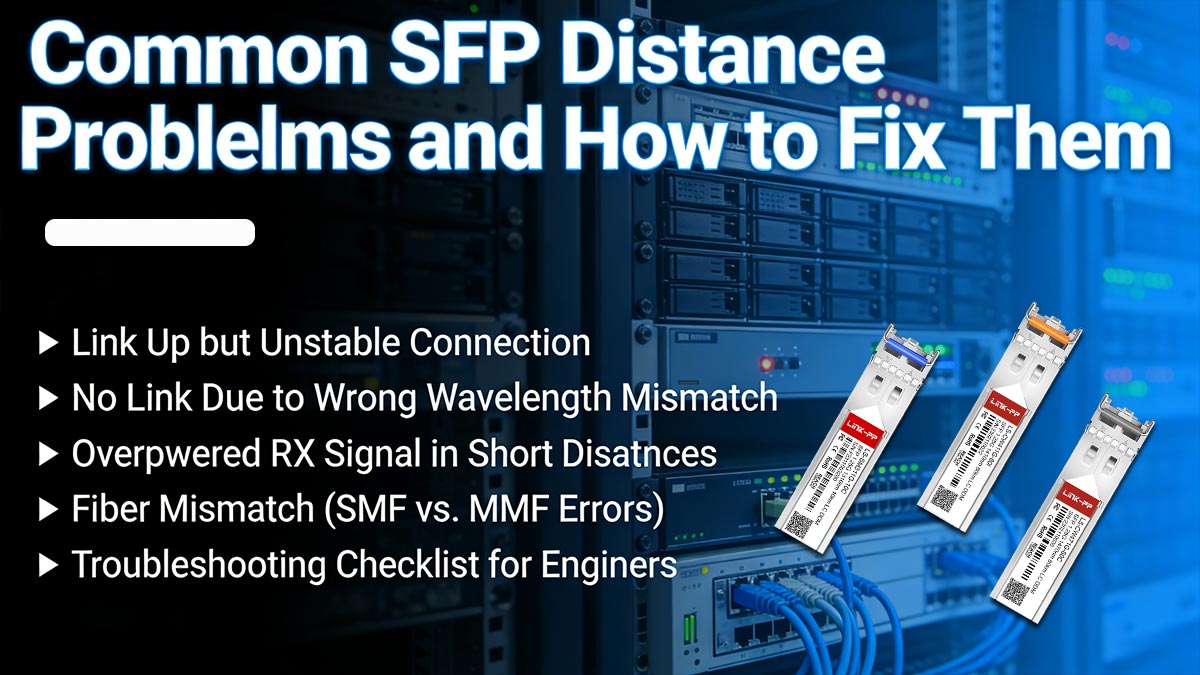
▶ Link Up but Unstable Connection
One of the most confusing issues in real deployments is when the link appears “up” but traffic is unstable.
Symptoms:
Intermittent packet loss
High latency spikes
CRC errors or frame drops
Flapping interface status
Common causes:
Marginal link budget (too close to maximum distance limit)
Dirty or partially damaged connectors
Poor quality or aging fiber cable
Insufficient safety margin in design
Fix:
Clean all fiber connectors (LC/SC)
Recalculate link budget with 3–5 dB margin
Replace low-quality patch cables
Reduce link distance or upgrade to higher-grade optics
Key insight: A “working” SFP link is not always a “stable” SFP link.
▶ No Link Due to Wrong Wavelength Mismatch
A very common issue is wavelength incompatibility between transceivers.
Symptoms:
No link light (LOS state)
Switch port shows “down”
No optical signal detected
Typical mistakes:
Using 850nm SR on single-mode fiber
Pairing mismatched optics (SR ↔ LR)
Mixing vendor-specific incompatible modules
Fix:
Ensure both ends use identical or compatible optics
Match wavelength:
850nm → multimode fiber
1310nm → single-mode fiber
Verify transceiver compatibility with switch platform
Key insight: Wavelength mismatch is one of the fastest ways to completely break an SFP link.
▶ Overpowered RX Signal in Short Distances
Short-distance links can also fail when optical power is too high.
Symptoms:
Link comes up but errors appear immediately
Intermittent disconnects on short fiber runs
Receiver overload warnings (on supported devices)
Cause:
Using long-range (LR/ER) optics on very short fiber links
Fix:
Add optical attenuators (1–10 dB depending on design)
Switch to SR (short-range) optics
Increase patch cable length if feasible
Key insight: Too much optical power is just as harmful as too little.
▶ Fiber Mismatch (SMF vs. MMF Errors)
Another frequent deployment error is using the wrong fiber type with the wrong SFP module.
Symptoms:
No link or very weak signal
Extremely high error rates
Unstable or intermittent connection
Common mismatches:
SR optics used on single-mode fiber (OS1/OS2)
LR optics used on multimode fiber (OM2/OM3/OM4)
Mixed fiber infrastructure in the same path
Fix:
Match fiber type correctly:
Multimode fiber → SR (850nm)
Single-mode fiber → LR/ER (1310nm/1550nm)
Replace incompatible patch cables
Audit entire fiber path, not just endpoints
📌 Key insight: Fiber type mismatch is often mistaken for “bad SFP modules.”
▶ Troubleshooting Checklist for Engineers
To systematically diagnose SFP distance issues, follow this structured checklist:
✔ Physical Layer Checks
Inspect and clean all fiber connectors
Verify correct LC/SC connections
Check for cable bends or damage
✔ Optical Compatibility Checks
Confirm wavelength match (850nm vs. 1310nm)
Verify fiber type (SMF vs. MMF)
Ensure compatible SFP standards (SR/LR/ER)
✔ Link Budget Validation
Recalculate total optical loss
Confirm TX power vs RX sensitivity
Add minimum 3–5 dB safety margin
✔ Device & Configuration Checks
Verify switch SFP compatibility
Check for vendor restrictions or coding issues
Ensure correct speed negotiation (1G / 2.5G / 10G)
✔ Performance Monitoring
Monitor error counters (CRC, FCS errors)
Check optical power levels (if supported)
Observe link stability over time
Most SFP distance problems are not caused by hardware failure, but by optical mismatches, poor link planning, or environmental degradation.
By systematically checking wavelength, fiber type, and link budget, engineers can resolve the majority of issues without replacing equipment—ensuring stable and predictable SFP distance performance in real-world networks.
🟢 FAQ — SFP Distance and Fiber Range Explained
Q1: What is the distance of SFP fiber?
The “distance of SFP fiber” is not a fixed value because it depends on the optical transceiver type and fiber infrastructure used in the link.
In general:
Short-range SFP (SR, 850nm over multimode fiber): up to ~300–550 meters
Long-range SFP (LR, 1310nm over single-mode fiber): up to ~10 kilometers
Extended-range SFP (ER/ZR, 1550nm systems): 40 km to 80+ km depending on design
Key clarification: The fiber itself does not define the distance—the combination of fiber type + SFP optics determines the usable range.
Q2: What is the range of SFP fiber?
The range of SFP fiber refers to the maximum stable transmission distance supported by a specific optical system, not a universal fiber limit.
Typical ranges include:
Multimode systems: short-range, optimized for intra-building connectivity
Single-mode systems: medium to long-range, suitable for campus and metro networks
Long-haul systems: designed for telecom backbone and intercity links
Important insight: The same fiber cable can support different ranges depending on the SFP module used at both ends.
Q3: Can SFP work beyond rated distance?
In some cases, SFP modules may appear to function beyond their rated distance, but this is not guaranteed or recommended for stable deployment.
Possible outcomes:
The link may establish temporarily
Increased bit errors or instability may occur
Performance may degrade under temperature or load changes
Key insight: SFP distance ratings are engineering limits based on reliable operation—not strict physical cutoffs.
For production networks, exceeding rated distance introduces significant risk and should be avoided.
Q4: Why does my SFP link fail over long distance?
Long-distance SFP failures usually occur when the optical signal becomes too weak or degraded to maintain reliable communication.
Common underlying causes include:
Excessive fiber attenuation over distance
Insufficient optical power margin
Unaccounted connector or splice losses
Environmental stress affecting signal quality
Important clarification: A link may still “connect” at long distance but fail at the data integrity level due to insufficient signal quality.
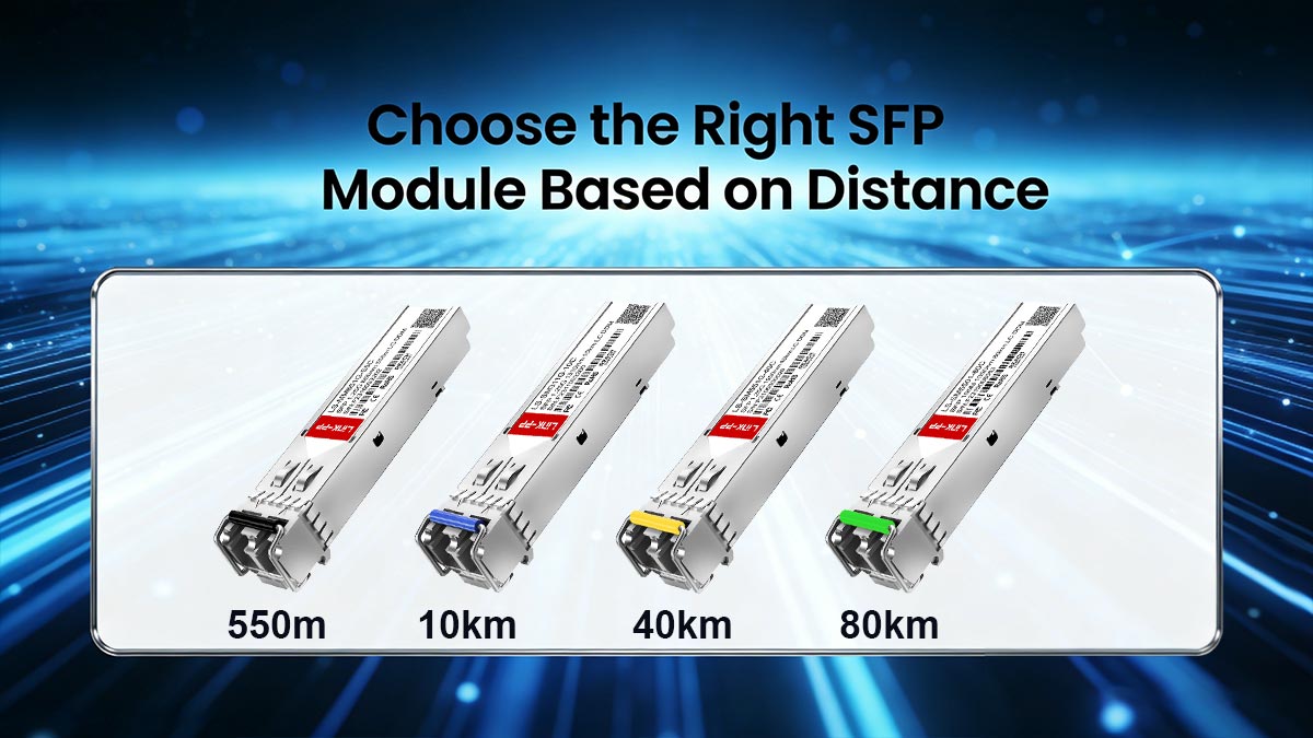
🟢 How to Choose the Right SFP Module Based on Distance
Selecting the right SFP module based on distance is not just a procurement decision—it is a network design decision that directly impacts stability, performance, and long-term maintenance cost. A structured selection process helps avoid most real-world fiber issues before deployment even begins.
Step-by-Step Selection Framework
1. Required Distance
Start by clearly defining the maximum link distance in your network design.
Short-range (≤ 550m): typical for data centers or building interconnects
Medium-range (1–10km): campus or metro access networks
Long-range (10km+): backbone or intercity links
Key principle: Always design slightly above your real distance requirement to maintain a safety margin.
2. Fiber Type Availability
Check what fiber infrastructure is already deployed:
Multimode fiber (OM1/OM2/OM3/OM4) → short-range SR modules
Single-mode fiber (OS1/OS2) → long-range LR/ER modules
Key insight: The SFP module must match the existing fiber—not the other way around.
3. Wavelength Selection (850nm vs. 1310nm)
Wavelength directly determines signal behavior and usable distance.
850nm (SR, VCSEL-based):
Best for short-distance, high-density environments
Works with multimode fiber
1310nm (LR):
Best for stable medium-to-long distance transmission
Works with single-mode fiber
Key principle: Wavelength mismatch is one of the most common causes of link failure in deployment.
4. Switch Compatibility Check
Not all switches accept all SFP Transceivers equally.
Before deployment:
Confirm vendor compatibility list
Check for OEM coding restrictions
Verify supported speed (1G / 2.5G / 10G)
Ensure firmware compatibility
Key insight: Even perfectly matched optics will fail if the switch rejects the module.
5. Cost-Performance Optimization Strategy
Choosing SFP modules is also a balance between budget and long-term stability.
SR modules: lower cost, limited range
LR modules: higher cost, but greater flexibility
Compatible third-party optics: cost-effective alternative if properly validated
Best practice: Optimize for total lifecycle cost, not just unit price.
6. Risk Reduction Checklist Before Deployment
Before final installation, validate the following:
✔ Distance is within optical budget (with safety margin)
✔ Fiber type matches SFP specification
✔ Wavelength compatibility confirmed
✔ Connectors are clean and properly installed
✔ Switch compatibility verified
✔ Link budget calculation completed
✔ Test link stability under real traffic load
Key insight: Most SFP failures are preventable with proper pre-deployment validation.
Final Insight
Choosing the right SFP module based on distance is a structured engineering process that combines optics, fiber type, and network design discipline. When done correctly, it significantly reduces troubleshooting effort and ensures long-term link stability.
For engineers and procurement teams looking for reliable and cost-effective optical solutions, you can explore professionally tested options at the LINK-PP Official Store, where compatibility and performance validation are prioritized for real-world deployments.


