

SFP Small Form-Factor Pluggable Transceivers are compact, hot-pluggable network modules that play a critical role in modern data communication infrastructure. Designed to connect switches, routers, and other network devices to fiber optic or copper cabling, SFP modules provide a flexible and scalable solution for networks ranging from enterprise data centers to telecommunications backbones. Their versatility allows network administrators to upgrade or adapt network links without replacing the entire device, enabling high-density port deployment and cost-efficient scalability.
Through this guide, you will learn the essential functions of SFP transceivers, understand the differences between SFP, SFP+, and QSFP modules, and explore key parameters such as supported speeds, distance limitations, and connector types (LC-UPC vs. LC-APC). Additionally, the article highlights best practices for selecting compatible modules, troubleshooting common issues, and ensuring optimal performance across diverse network environments.
By the end of this article, you will gain actionable insights into:
Identifying the right SFP module for specific network requirements.
Comparing SFP with alternative solutions such as RJ45 and SFP+ links.
Understanding technical specifications and operational considerations for reliable deployment.
This introduction sets the stage for a detailed exploration of SFP types, applications, and compatibility considerations, providing both engineers and procurement specialists with authoritative guidance for informed decision-making.
🔶 What Is An SFP (Small Form-Factor Pluggable) Transceiver — Definition & How It Works
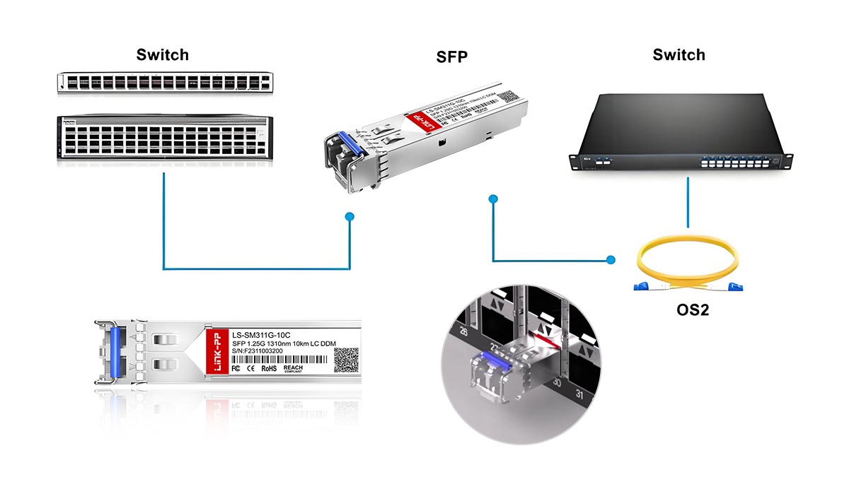
A Small Form-Factor Pluggable (SFP) transceiver is a compact, hot-swappable network module designed to interface network devices—such as switches, routers, and storage systems—with fiber optic or copper cabling. Often referred to as a “mini-GBIC” (Gigabit Interface Converter), the SFP module conforms to the Multi-Source Agreement (MSA) SFP standard established by the Small Form Factor Committee (SFF) and ensures interoperability across different vendors.
Small Form-Factor Pluggable Definition
SFP transceivers serve as modular physical layer devices that convert electrical signals into optical signals for transmission over fiber, or adapt to copper interfaces for Ethernet links. Their compact size allows network devices to support high port densities without sacrificing performance. Key characteristics include:
Hot-pluggable design: Modules can be inserted or removed while the device is powered, minimizing network downtime.
Standardized form factor: The physical dimensions (approximately 13.4 mm × 56.5 mm × 8.5 mm) allow compatibility with any SFP-compliant port.
Versatile interface support: Compatible with multiple data standards, including 1GBASE-T, 1000BASE-SX/LX, Fibre Channel, and SONET.
How SFP Works
The SFP transceiver functions as a bidirectional signal converter between a network device and the transmission medium:
Electrical-to-Optical Conversion (for fiber): Inside the SFP, an electrical input from the host device is converted into a light signal using a laser diode or LED. The signal is then transmitted through single-mode or multi-mode fiber to the receiving device.
Optical-to-Electrical Conversion (for fiber): At the receiving end, a photodiode within the SFP converts the incoming light signal back into an electrical signal for processing by the host device.
Copper Interface (optional): Some SFP modules support copper cabling (1GBASE-T), directly transmitting and receiving electrical signals without optical conversion.
Key Parameters
Data Rate: Standard SFP supports 1 Gbps; SFP+ supports 10 Gbps; SFP28 supports 25–28 Gbps.
Transmission Distance: Modules are classified based on reach—Short Reach (SR), Long Reach (LR), and Extended Reach (ER). For example, 1GBASE-LX SFP can reach up to 10 km over single-mode fiber.
Connector Type: LC is the most common connector; end-face polish can be UPC (Ultra-Physical Contact) or APC (Angled Physical Contact), affecting insertion loss and return loss.
By standardizing the physical form and electrical/optical interfaces, SFP transceivers enable flexible network deployment. Network administrators can upgrade link speeds, switch from fiber to copper, or replace failed modules without replacing the entire switch or router, achieving both scalability and operational efficiency.
References:
SFF-8472: Digital Diagnostic Monitoring Interface for SFP Modules MSA / SFF Committee
Vendor SFP Datasheet: Cisco 1G/10G SFP Modules, Finisar FTLX8571D3BCL SFP+
🔶 Choosing The Right Small Form-Factor Pluggable Transceiver: MMF vs. SMF, SR/LR/ER, And (LC-UPC vs. LC-APC)
Selecting the correct SFP (Small Form-Factor Pluggable) transceiver requires evaluating several key parameters: fiber type (multimode vs. single-mode), transmission distance (SR/LR/ER), and connector endface type (UPC vs. APC). These factors directly affect link performance, compatibility, and long-term reliability.
In practical deployments, most connection problems are caused not by the transceiver itself but by incorrect fiber selection, connector mismatch, or misunderstanding of optical reach specifications. A systematic approach to selection helps avoid these common errors.
MMF vs. SMF — Choosing the Correct Fiber Type
Optical SFP modules are designed to operate with either multimode fiber (MMF) or single-mode fiber (SMF). The difference primarily relates to core diameter, wavelength, and transmission distance.
Multimode Fiber (MMF)
Typical core size: 50 µm or 62.5 µm
Typical wavelengths: 850 nm
Common modules: 1000BASE-SX, 10GBASE-SR, 25GBASE-SR
Typical reach: 100–550 meters depending on fiber grade (OM3/OM4/OM5)
MMF is commonly used in data centers and short-distance enterprise links, where lower cost optics and existing structured cabling make it practical.
Single-Mode Fiber (SMF)
Typical core size: ~9 µm
Typical wavelengths: 1310 nm or 1550 nm
Common modules: 1000BASE-LX, 10GBASE-LR, 10GBASE-ER
Typical reach: 10 km to 40 km or more
SMF is widely used in campus networks, metro networks, and telecommunications infrastructure where long-distance transmission is required.
SR vs. LR vs. ER — Understanding Optical Reach Classes
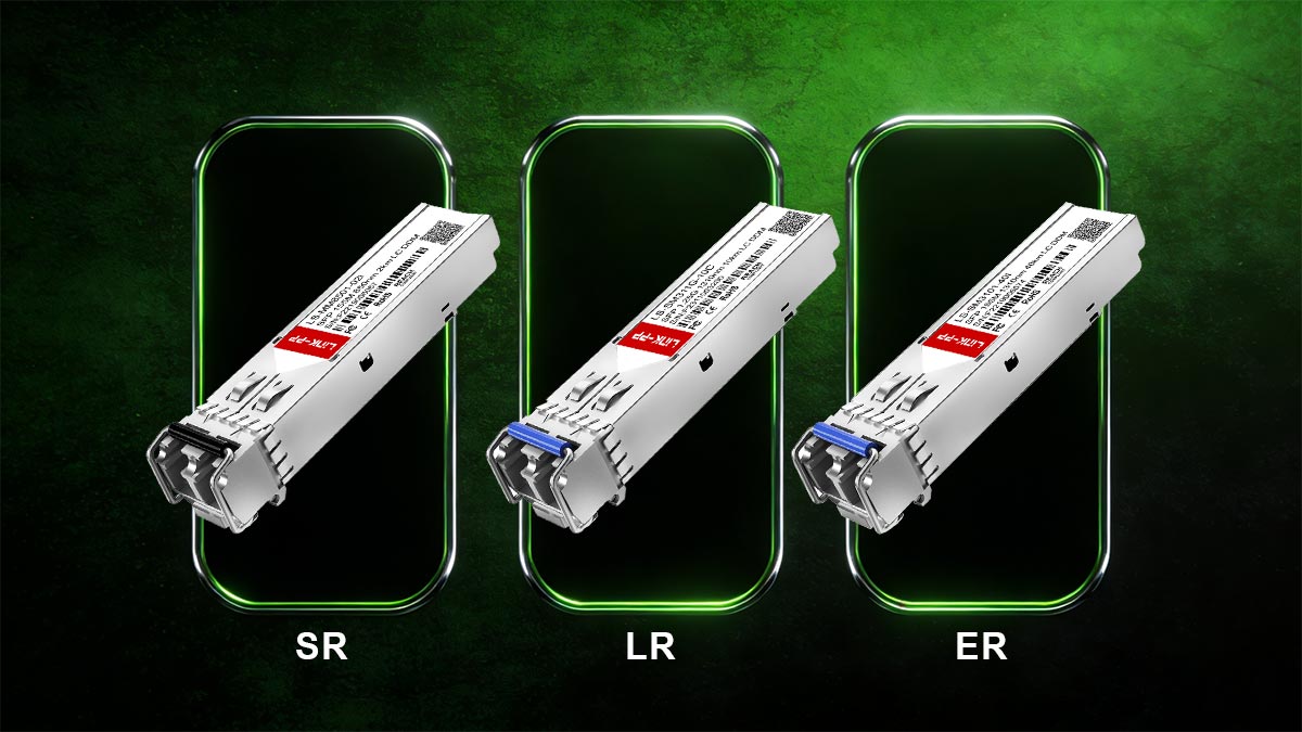
Small Form-Factor Pluggable modules are often categorized based on transmission distance and wavelength, using standard designations such as SR (Short Reach), LR (Long Reach), and ER (Extended Reach).
Optical Type | Typical Wavelength | Fiber Type | Typical Distance | Common Applications |
|---|---|---|---|---|
850 nm | MMF | 100–400 m | Data center interconnects | |
1310 nm | SMF | up to ~10 km | Campus backbone links | |
1550 nm | SMF | up to ~40 km | Metro and telecom networks |
For example:
10GBASE-SR SFP+ modules are optimized for short-distance multimode fiber links inside data centers.
10GBASE-LR SFP+ modules support single-mode fiber links up to approximately 10 km.
10GBASE-ER SFP+ modules are designed for long-distance metro or carrier networks.
Understanding these reach categories ensures the selected transceiver matches the physical network topology and fiber infrastructure.
Connector Endfaces: LC-UPC vs. LC-APC
Most SFP optical modules use LC duplex connectors, but the polish type of the fiber endface—UPC or APC—can significantly affect optical performance.
LC-UPC (Ultra Physical Contact)
Flat or slightly curved endface
Typical return loss: ~50 dB
Widely used in Ethernet and data center networks
LC-APC (Angled Physical Contact)
8-degree angled endface
Higher return loss performance (~60 dB or better)
In most Ethernet SFP deployments, LC-UPC connectors are standard.
How To Identify UPC vs. APC Connectors
Network engineers can typically distinguish connector types by color and physical design:
Connector Type | Typical Color | Endface Angle |
|---|---|---|
UPC | Blue | Flat |
APC | Green | 8° angle |
However, visual inspection alone is not always reliable. The safest approach is to verify:
Transceiver datasheet
Fiber patch cable specification
Network equipment documentation
Common Mistakes When Selecting Small Form-Factor Pluggable Optics
Even experienced network installers occasionally encounter compatibility issues. The most common mistakes include:
Mixing multimode modules with single-mode fiber
(e.g., using an SR module on SMF).Connecting UPC optics to APC fiber connectors
which causes excessive reflection and link instability.Selecting insufficient transmission distance
such as using SR modules for links exceeding multimode limits.Ignoring vendor compatibility requirements
when installing third-party SFP modules.
Preventing these errors requires verifying SFP module specifications, fiber type, connector polish, and supported Ethernet standards before deployment.
SFP Selection Decision Matrix
The following simplified matrix can help engineers choose the correct transceiver based on network requirements.
Network Scenario | Recommended Module | Fiber Type | Connector |
|---|---|---|---|
Data center rack-to-rack | MMF (OM3/OM4) | LC-UPC | |
Campus building link | SMF | LC-UPC | |
Metro or telecom backbone | SMF | LC-UPC/APC depending on network | |
Passive optical networks | Specialized optics | SMF | LC-APC |
This approach ensures that transceiver specifications match the optical infrastructure and network performance requirements.
Choosing the right Small Form-Factor Pluggable transceiver Tips:
Choosing the right SFP transceiver involves aligning fiber type, transmission distance, and connector endface polish with the physical network environment. In most enterprise Ethernet deployments:
SR modules + multimode fiber are used for short-distance data center links.
LR modules + single-mode fiber are used for campus or building connections.
LC-UPC connectors are the standard interface for Ethernet SFP optics.
By carefully matching these parameters, network operators can ensure stable optical links, optimal performance, and long-term infrastructure scalability.
🔶 SFP Types And Form Factors: SFP, SFP+, SFP28, QSFP — Speeds And Common Use Cases
The Small Form-Factor Pluggable (SFP) ecosystem has evolved significantly to support increasing bandwidth requirements in enterprise networks, cloud infrastructure, and telecommunications systems. While the original SFP standard was designed for Gigabit Ethernet, newer variants such as SFP+, SFP28, and QSFP extend the same modular concept to much higher data rates while maintaining compact size and hot-pluggable functionality.
These form factors follow specifications defined by the Small Form Factor Committee and the SFP Multi‑Source Agreement (MSA) Group, which ensure interoperability among different vendors’ modules and host equipment. Because of this standardization, network engineers can scale network capacity simply by selecting the appropriate optical module type without replacing the underlying switching hardware.
Below are the most widely used pluggable transceiver form factors in modern networks.
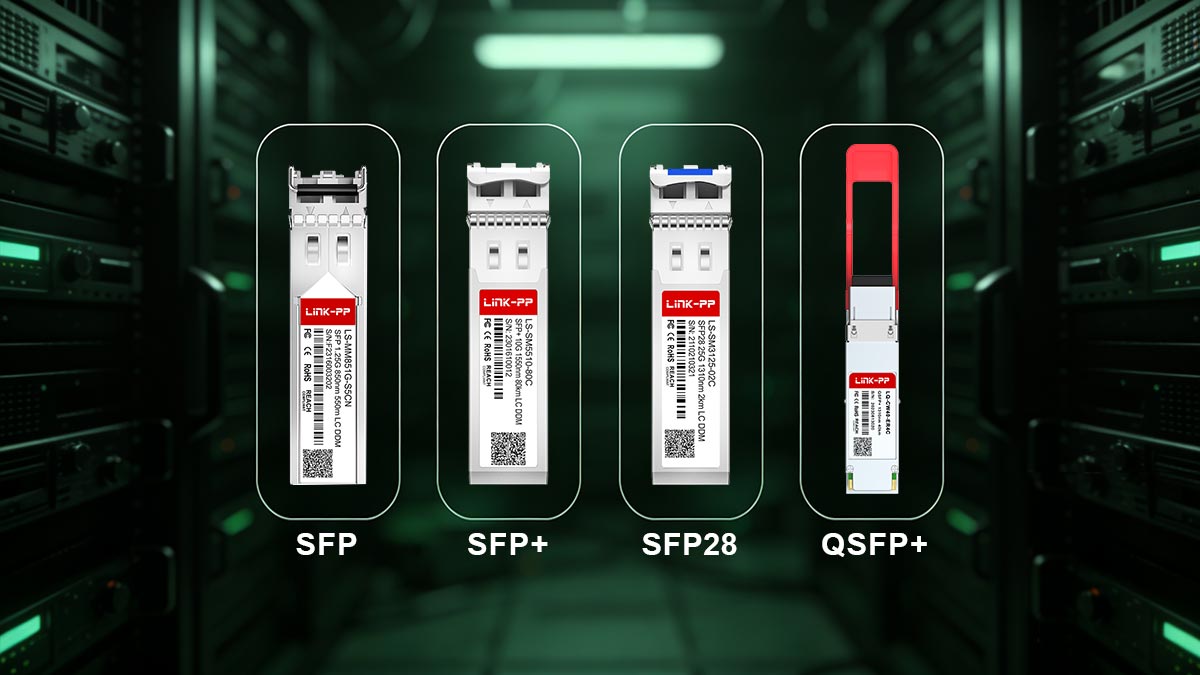
SFP (1G)
The original SFP (Small Form-Factor Pluggable) module was introduced as a compact replacement for the older GBIC transceiver. It is primarily designed for 1 Gigabit Ethernet and Fibre Channel links.
Typical characteristics include:
Maximum Data Rate: up to 1.25 Gb/s
Common Standards: 1000BASE-SX, 1000BASE-LX, 1000BASE-ZX, and 1000BASE-T
Typical Connectors: LC duplex for fiber modules, RJ45 for copper variants
Typical Reach:
SX (850 nm MMF): up to ~550 m
LX (1310 nm SMF): up to ~10 km
ZX (1550 nm SMF): up to ~80 km
SFP modules remain widely deployed in enterprise access networks, campus networks, industrial Ethernet, and legacy data center environments where 1G connectivity is sufficient.
SFP+ (10G)
SFP+ (Enhanced Small Form-Factor Pluggable) is an evolution of the SFP design that supports 10 Gigabit Ethernet while maintaining nearly identical mechanical dimensions. Because of the shared form factor, many switches provide SFP/SFP+ combo ports, though SFP modules cannot operate at 10G speeds.
Typical characteristics include:
Maximum Data Rate: up to 10.3 Gb/s
Common Standards: 10GBASE-SR, 10GBASE-LR, 10GBASE-ER, 10GBASE-ZR
Typical Reach:
SR (850 nm MMF): up to ~300–400 m
LR (1310 nm SMF): up to ~10 km
ER (1550 nm SMF): up to ~40 km
Cable Options: optical fiber, DAC (Direct Attach Copper), or AOC (Active Optical Cable)
SFP+ modules are commonly used in data center aggregation layers, high-speed enterprise backbones, and telecom edge networks where 10G bandwidth is required.
SFP28 (25/28G)
SFP28 extends the SFP+ electrical interface to support 25 Gb/s Ethernet, providing a cost-efficient upgrade path for high-density data center networks. It maintains the same physical footprint as SFP+, allowing equipment vendors to design switches with higher throughput without increasing port size.
Typical characteristics include:
Maximum Data Rate: 25–28 Gb/s
Common Standards: 25GBASE-SR, 25GBASE-LR
Typical Reach:
SR (MMF): up to ~70–100 m depending on fiber grade
LR (SMF): up to ~10 km
SFP28 is widely deployed in modern hyperscale data centers, cloud infrastructure, and server-to-switch connections, where 25G links offer an optimal balance between cost, power efficiency, and performance.
QSFP Family (40G, 100G And Beyond)
The QSFP (Quad Small Form-Factor Pluggable) family increases bandwidth by combining four high-speed transmit and receive channels in a single module. This architecture allows significantly higher aggregate data rates compared with single-lane SFP modules.
Common variants include:
QSFP+ — 40 Gb/s Ethernet
QSFP28 — 100 Gb/s Ethernet
QSFP56 / QSFP112 — 200–400 Gb/s for next-generation data center fabrics
These modules are widely used in core data center switching, hyperscale cloud infrastructure, and high-capacity telecom transport networks where extremely high throughput and port density are required.
Comparison Of Common Pluggable Transceiver Types
Form Factor | Typical Speed | Fiber Types | Typical Reach | Common Applications |
|---|---|---|---|---|
SFP | 1 Gb/s | MMF / SMF / Copper | up to ~80 km | Enterprise access networks, industrial Ethernet |
SFP+ | 10 Gb/s | MMF / SMF / DAC | up to ~40 km | Data center aggregation, enterprise backbone |
SFP28 | 25 Gb/s | MMF / SMF | up to ~10 km | Hyperscale data centers, server-to-switch links |
QSFP+ / QSFP28 | 40–100 Gb/s | MMF / SMF | up to ~10–40 km | Core switching, cloud infrastructure |
Key Takeaway
The evolution from SFP to SFP+, SFP28, and QSFP demonstrates how pluggable optics have scaled with network bandwidth demands while maintaining a standardized modular design. This modularity enables network operators to increase capacity, upgrade speeds, or change transmission media simply by replacing the transceiver, without redesigning the entire networking platform.
🔶 Third-Party SFP Compatibility And Warranty Concerns — Vendor Lock-In Explained
In modern network deployments, many organizations consider third-party or “compatible” SFP transceivers as an alternative to original equipment manufacturer (OEM) optics. While OEM modules from vendors such as Cisco Systems or Juniper Networks are guaranteed to match their platforms, they are often significantly more expensive than multi-vendor compatible optics.
This price difference has led to widespread industry discussion around vendor lock-in, interoperability, and warranty implications. The SFP ecosystem itself is built on open specifications defined by the SFP Multi‑Source Agreement (MSA) Group, which standardize the physical form factor and electrical interface of pluggable optics. However, some network vendors implement firmware checks that verify the transceiver’s identification data.
The following FAQ addresses the most common concerns raised by network engineers and procurement teams when evaluating third-party SFP modules.
Do Third-Party SFP Modules Work With Major Switch Vendors?
Yes—most of the time.
Compatible optics are typically designed to follow the same MSA standards as OEM modules. Many third-party manufacturers program the module’s EEPROM identification data so that the switch recognizes the optic as a supported device.
In practice, compatible optics are widely used in:
enterprise campus networks
data centers
telecom edge networks
However, compatibility can depend on:
the switch firmware version
the specific module model
the vendor’s optical validation policy
Because of this, reputable suppliers often provide a tested compatibility matrix listing supported switches and routers.
Do Third-Party SFPs Void Equipment Warranties?
In most cases, installing a third-party SFP does not automatically void a hardware warranty.
Major network vendors typically cannot invalidate a device warranty solely because a compatible optic is used. However, if a network fault is traced directly to an unsupported module, support teams may require the optic to be replaced with an OEM part before troubleshooting continues.
Best practice is to:
Verify the optic against a vendor compatibility list.
Keep OEM optics available for diagnostics if required by support teams.
Use modules from suppliers that provide lifetime warranties and interoperability testing.
Why Do Some Switches Reject Third-Party Optics?
Some network vendors implement firmware validation mechanisms that check module identification information stored in the transceiver’s EEPROM.
These checks may verify:
vendor name
product identifier (PID)
optical specification code
supported data rates
If the EEPROM data does not match an approved profile, the switch may display warnings such as:
“Unsupported transceiver detected”
“Non-qualified module installed”
Many compatible optics are programmed with vendor-specific EEPROM profiles to ensure that switches recognize them correctly.
How To Check Small Form-Factor Pluggable Transceiver Compatibility
Before purchasing or installing optics, network administrators should verify compatibility using the following steps:
1. Check the Switch Hardware Documentation
Review the supported transceiver list published by the equipment manufacturer.
2. Confirm Firmware Requirements
Some firmware versions add or remove support for specific optics.
3. Use a Compatibility Matrix
Reputable suppliers provide switch compatibility tables covering platforms from vendors such as Arista Networks, Hewlett Packard Enterprise, and Juniper Networks.
4. Verify Optical Specifications
Ensure that the module’s wavelength, distance class, and connector type match the existing fiber infrastructure.
Many network equipment suppliers publish these lists in downloadable format. Providing a switch compatibility matrix can significantly simplify the selection process for engineers and procurement teams.
How To Read SFP EEPROM Information
Every SFP module contains an internal EEPROM (Electrically Erasable Programmable Read-Only Memory) that stores identification and diagnostic information. This data structure is standardized under the SFF‑8472 Digital Diagnostic Monitoring Interface specification.
Common EEPROM fields include:
Field | Description |
|---|---|
Vendor Name | Manufacturer identifier |
Part Number | Optical module model |
Serial Number | Unique hardware ID |
Supported Speed | e.g., 1G, 10G |
Wavelength | Optical transmission wavelength |
DOM/DDM Data | Real-time temperature, voltage, Tx/Rx power |
Most switches allow administrators to read these values through command-line interfaces such as:
show interface transceiver detailsMonitoring EEPROM and DOM/DDM telemetry helps engineers verify module authenticity and detect potential optical issues before link failure occurs.
Best Practice For Using 3rd-Party SFP
When sourced from reputable manufacturers and tested for interoperability, compatible optics can provide reliable performance with significant cost savings. To minimize deployment risks:
purchase optics from vendors that provide compatibility testing and firmware support
verify modules against a platform compatibility database
maintain clear documentation of installed optics in the network inventory
For organizations deploying large numbers of transceivers, accessing a downloadable switch compatibility matrix can help streamline procurement and avoid installation issues.
🔶 Troubleshooting & Best Practices: Hot-Swap, DOM/DDM Readings, LOS Faults, And Fiber Cleaning
Even though SFP transceivers are designed for reliability and hot-swappable operation, optical links can occasionally experience faults such as Loss of Signal (LOS), high optical attenuation, or transceiver recognition errors. Effective troubleshooting requires checking the transceiver status, digital diagnostics, fiber condition, and switch interface configuration.

The following best practices and step-by-step checks are commonly used by network engineers to quickly diagnose SFP link issues.
Safe Hot-Swap Procedures For SFP Modules
One major advantage of SFP optics is their hot-pluggable design, defined by the SFP Multi-Source Agreement specification. This means modules can be inserted or removed while the switch remains powered on.
Best practice for hot-swapping:
Verify port status first
Check whether the interface is active before removing the module.Disable the interface if required
Some administrators prefer disabling the port to prevent temporary link flapping.Use the transceiver latch correctly
Pull the bail latch or release tab before removing the module.Insert the new module firmly
Ensure the module is fully seated in the cage.Reconnect the fiber cable carefully
Avoid bending the fiber beyond its minimum bend radius.
Hot-swapping generally takes only a few seconds, allowing network maintenance without system downtime.
Using DOM/DDM Monitoring To Diagnose Optical Links
Most modern SFP and SFP+ modules support Digital Optical Monitoring (DOM) or Digital Diagnostic Monitoring (DDM) as defined in the SFF-8472 specification.
DOM provides real-time telemetry that helps identify optical problems before link failure occurs.
Typical parameters include:
Parameter | Description | Typical Use |
|---|---|---|
Temperature | Internal module temperature | Detect overheating |
Voltage | Supply voltage | Identify power anomalies |
Tx Power | Optical transmit power | Verify laser performance |
Rx Power | Optical receive power | Detect attenuation or dirty connectors |
Bias Current | Laser bias current | Monitor laser aging |
Example command (common on many switches):
show interface transceiver detailsor
show interfaces diagnostics opticsThese commands display real-time optical values that can help determine whether the issue is optical loss, fiber damage, or a failing module.
Understanding LOS (Loss Of Signal) Errors
A Loss of Signal (LOS) alarm indicates that the receiver is not detecting sufficient optical power from the remote transmitter.
Common causes include:
fiber cable disconnected
incorrect fiber type (MMF vs. SMF mismatch)
excessive distance beyond module specification
dirty or damaged connectors
incompatible optical modules
Typical troubleshooting steps:
Verify fiber polarity (Tx ↔ Rx)
Ensure transmit and receive fibers are not reversed.Check connector cleanliness
Dust or contamination is a frequent cause of optical loss.Confirm module compatibility
Ensure both ends use matching optics (e.g., SR ↔ SR or LR ↔ LR).Measure received optical power
Compare DOM Rx values against the module’s sensitivity specification.
If the Rx optical power is below the minimum threshold, the switch will typically trigger a LOS alarm.
Interpreting Common SFP LED Indicators
Many switches include status LEDs near the SFP port to indicate link condition.
Typical meanings include:
LED State | Meaning |
|---|---|
Solid Green | Link active |
Blinking Green | Data activity |
Amber / Orange | Link fault or speed mismatch |
Off | No link detected |
Exact LED behavior varies by manufacturer, so engineers should always consult the device hardware manual for precise definitions.
Fiber Cleaning Best Practices
Optical connectors are extremely sensitive to microscopic dust particles, which can significantly degrade signal quality.
Industry studies show that contaminated fiber connectors are one of the most common causes of optical link failures.
Recommended cleaning procedure:
Inspect the connector with a fiber microscope if available
Use lint-free wipes or dedicated fiber cleaning tools
Clean the connector before every reconnection
Avoid touching the ferrule endface
Use protective dust caps when cables are not connected
Proper fiber cleaning can prevent signal attenuation, high bit error rates, and intermittent link failures.
Quick SFP Small Form-Factor Pluggable Troubleshooting Checklist
For rapid diagnosis, engineers can follow this simplified checklist:
Verify the correct SFP module type is installed.
Check fiber polarity and cable connections.
Inspect and clean fiber connectors.
Review DOM/DDM optical power levels.
Confirm switch compatibility and firmware support.
Following these steps helps resolve most SFP-related issues without replacing hardware unnecessarily.
🔶 FAQs About SFP Small Form-Factor Pluggable Transceivers
1. What Does a Small Form-Factor Pluggable (SFP) Transceiver Do?
An SFP transceiver connects network equipment—such as switches, routers, and storage systems—to fiber optic or copper cabling. It converts electrical signals from the host device into optical signals for transmission over fiber, and converts received optical signals back into electrical signals for processing.
Because SFP modules are hot-pluggable and standardized, they allow network administrators to upgrade link speeds, change transmission media, or replace failed optics without replacing the entire networking device.
2. What Is the Purpose of an SFP Port?
An SFP port provides a modular interface that accepts interchangeable SFP transceivers. This design allows network devices to support multiple types of connections, including:
multimode fiber links for short-distance communication
single-mode fiber links for long-distance transmission
copper Ethernet connections using RJ45 SFP modules
The modular design improves network flexibility, scalability, and upgradeability compared with fixed network interfaces.
3. Is SFP Faster Than RJ45?
SFP itself is not inherently faster than RJ45, because speed depends on the Ethernet standard used.
For example:
1G SFP (1000BASE-SX/LX) operates at 1 Gbps, similar to 1GBASE-T RJ45.
SFP+ modules support 10 Gbps, which is comparable to 10GBASE-T RJ45.
However, SFP-based links—especially SFP+ with fiber or DAC cables—often provide lower latency and lower power consumption compared with 10GBASE-T copper interfaces.
4. Are SFP Connectors UPC or APC?
Most Ethernet SFP optical modules use LC connectors with UPC (Ultra Physical Contact) polish. UPC connectors provide sufficient return loss performance for typical Ethernet and data center applications.
APC (Angled Physical Contact) connectors, which use an 8-degree angled endface, are more commonly used in passive optical networks (PON), FTTH infrastructure, and high-reflection-sensitive optical systems.
For standard Ethernet SFP modules, LC-UPC connectors are the industry default.
5. What Are the Main Types of SFP Modules?
The most common SFP-related transceiver form factors include:
SFP – typically used for 1 Gigabit Ethernet connections
SFP+ – supports 10 Gigabit Ethernet
SFP28 – designed for 25 Gigabit Ethernet
QSFP family (QSFP+, QSFP28) – used for 40G, 100G, and higher-speed networking
These modules follow specifications defined by the Small Form Factor Committee and the SFP Multi-Source Agreement (MSA) Group, enabling interoperability between vendors.
6. Can Third-Party SFP Modules Work With Cisco or Other Switch Vendors?
Yes. Many third-party or compatible SFP modules are designed to meet the same MSA standards as OEM optics and can work with switches from vendors such as Cisco Systems, Juniper Networks, and Arista Networks.
However, compatibility depends on factors such as:
switch firmware version
module EEPROM identification data
vendor-specific validation mechanisms
For reliable operation, network administrators should verify modules using a switch compatibility matrix provided by the supplier.
🔶 Conclusion: Understanding the Role of SFP Small Form-Factor Pluggable Transceivers in Modern Networks

SFP Small Form-Factor Pluggable transceivers have become a fundamental component of modern network infrastructure. Their modular design allows switches, routers, and servers to support different transmission media, including multimode fiber, single-mode fiber, and copper Ethernet connections. By replacing the SFP module instead of the entire device, network engineers can upgrade link speeds, extend transmission distance, or adapt to new cabling standards with minimal disruption.
Today’s enterprise networks, data centers, and telecom environments commonly deploy standardized transceiver types such as SFP (1G), SFP+ (10G), SFP28 (25G), and the QSFP family for higher-bandwidth applications. Choosing the right optical module typically involves evaluating several factors, including fiber type (MMF vs SMF), optical standards like SR, LR, or ER, connector endfaces such as LC-UPC or LC-APC, and compatibility with the target switch or router.
When properly selected and maintained, SFP transceivers deliver reliable high-speed connectivity, low latency, and flexible scalability for evolving network architectures.
For organizations planning network upgrades or fiber deployments, reviewing detailed specifications and compatibility requirements is essential. Engineers can explore compatible SFP, SFP+, SFP28, and QSFP transceivers through the LINK-PP Official Store, download technical specifications, or contact technical support for guidance on selecting the most suitable module for specific network environments.


