


Signal distortion is any unwanted change in a signal’s original shape, timing, or characteristics. In the context of networking and data communication, signal distortion means the data your system sends isn’t quite the data it receives—leading to errors, lost information, and performance issues.
1. What Is Signal Distortion?
Signal distortion is the unwanted change of a signal’s original shape, timing, amplitude, or phase as it travels through cables, connectors, or devices. It corrupts the message and increases error rates .
In digital electronics, even though data is represented as 1s and 0s, the actual signal is analog and vulnerable to effects like reflection, loss, and crosstalk.
2. Common Types of Signal Distortion
Type | Description |
|---|---|
Amplitude Distortion | Uneven amplification or attenuation of different frequency components, leading to waveform alteration. |
Phase Distortion | Different frequency components experience varying phase shifts, causing waveform deformation. |
Nonlinear Distortion | When a signal passes through a nonlinear system, new frequency components (e.g., harmonics, intermodulation) are generated, significantly degrading signal quality. |
Transient Distortion | Rapid signal changes exceed the system’s response time, resulting in waveform stretching or delay. |
🔸 Attenuation & Insertion Loss
Signal amplitude decreases due to resistance and dielectric loss. In connectors such as RJ45 or optical fiber modules, attenuation reduces the signal strength and clarity.
🔸 Reflection & Impedance Mismatch
When impedance changes at a connector or trace, part of the signal reflects back, causing distortion or signal “ringing.” Proper termination is critical to minimize this reflection.
🔸 Crosstalk
Electromagnetic coupling between nearby signal lines (e.g. in RJ45 connectors or PC board differential pairs) causes interference, degrading signal clarity.
🔸 Dispersion (Optical Signals)
Fiber optics face chromatic dispersion, where different wavelengths travel at different speeds, and modal dispersion in multimode fiber, leading to pulse broadening and inter-symbol interference (ISI).
🔸 Non‑Linear Distortion
In optical modules or magnetic devices, high power or imperfect materials may produce harmonics or intermodulation, distorting the signal further.
3. Why Signal Distortion Matters
Higher Bit Error Rate (BER): Distortion increases errors in digital links, especially at Gigabit or higher speeds.
Closed Eye Diagrams: Eye diagrams visualize signal quality—if the “eye” closes, transmission reliability drops.
Reduced Bandwidth & Data Rate: Distorted signals carry less reliable information, limiting system performance.
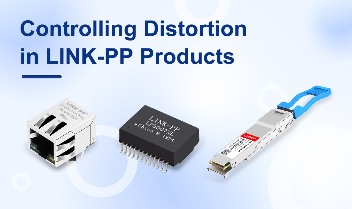
4. Controlling Distortion in LINK‑PP Products
LINK‑PP’s core products—RJ45 connectors, optical modules (e.g. SFP, 10 G, 25 G modules), and ethernet transformers—are designed to minimize signal distortion in these ways:
★ RJ45 Connectors
Built with precise impedance matching and Bob Smith termination to reduce reflection and insertion loss.
Low Return Loss and NEXT/FEXT crosstalk specifications ensure clean differential signals.
PCB layout guidelines (ground plane, trace pairing) are followed to maintain signal integrity.
★ Optical Modules
Optical transceivers include CDR (Clock Data Recovery) and FEC (Forward Error Correction) to correct waveform distortion and timing jitter.
MODULE specifications align with IEEE standards (e.g., stressed receiver sensitivity, eye mask compliance) to resist dispersion effects.
★ Ethernet Transformers
High Common‑Mode Rejection Ratio (CMRR) to suppress noise and maintain amplitude/phase balance.
Magnetic design resists saturation and intermodulation, preserving signal fidelity under power surges or ESD events.
5. Tips to Minimize Signal Distortion in Practice
Always maintain impedance matching across connectors, PC board traces, and cables.
Minimize length mismatches and stubs in RJ45 connector routing.
Use electromagnetic simulation tools to predict reflections and crosstalk.
For fiber links, follow best practices: select appropriate fiber type, control launch power, clean connectors regularly, and test eye diagrams and sensitivity masks.
6. Distortion vs. Noise vs. Attenuation: Quick Comparison
Distortion: Systematic change in signal shape; causes bit errors and compatibility issues.
Noise: Random interference added to the signal; reduces overall clarity.
Attenuation: Reduces signal strength but not its shape; excessive attenuation can make recovery difficult.
Conclusion
Signal distortion is the enemy of clean, reliable data transmission. From RJ45 connectors to optical modules and ethernet transformers, LINK‑PP integrates precise design and engineering to suppress distortion, improving signal integrity across network systems.
See Also
For more insights into the factors that affect signal distortion and overall signal integrity, explore these related articles from LINK‑PP’s Knowledge Center:
🔍 Insertion Loss: Impact on RJ45 MagJack
Learn how insertion loss affects signal strength and what connector design factors influence it.📉 Understanding Bit Error Rate (BER)
A deeper look at how signal distortion leads to BER and how it can be minimized in real applications.🚀 What Is Data Bandwidth?
Discover how signal quality impacts bandwidth and the importance of clean transmission paths.🔁 Return Loss in RJ45 Connectors
A key factor in minimizing reflection and maintaining signal fidelity in high-speed networks.🧭 Clock Data Recovery (CDR)
Understand how CDR helps reshape distorted signals and restore timing accuracy in digital transceivers.🛠️ Forward Error Correction (FEC)
Learn how FEC combats distortion and transmission errors in high-speed fiber optic systems.


