

As modern networks continue to expand across metropolitan and regional infrastructures, the demand for long-distance 10-gigabit Ethernet connectivity has grown significantly. Many engineers and network planners searching for SFP+ 100km solutions are attempting to determine whether a standard 10G SFP+ optical transceiver can realistically support fiber links approaching 100 kilometers, and if so, what technologies are required to achieve this distance reliably.
In standard Ethernet deployments, most commonly used 10G optical modules are designed for much shorter reaches. For example, 10GBASE-LR modules typically support distances of up to 10 km over single-mode fiber (SMF) using a 1310 nm wavelength, while 10GBASE-ER modules extend reach to approximately 40 km using 1550 nm optics. These specifications are defined in IEEE 10-Gigabit Ethernet standards and are widely implemented across enterprise switches, routers, and data center equipment.
However, long-haul optical transmission requirements—such as metro aggregation networks, campus interconnection, ISP backbone links, and utility infrastructure networks—often exceed these distances. In such cases, engineers turn to extended-reach SFP+ optics, commonly referred to as 10GBASE-ZR modules or long-haul 1550 nm SFP+ transceivers, which are designed with higher optical power budgets and more advanced laser technologies to support distances approaching 80 km to 100 km under appropriate conditions.
Achieving stable 100 km optical transmission at 10 Gbps is not simply a matter of selecting a longer-reach transceiver. Long-distance fiber links must account for several critical engineering factors, including:
Optical link budget (transmit power vs. receiver sensitivity)
Fiber attenuation, typically around 0.20–0.25 dB/km for standard G.652 single-mode fiber at 1550 nm
Connector and splice losses along the route
Chromatic dispersion and signal degradation over long distances
Potential requirements for optical amplification or DWDM transport systems
Because of these variables, real-world SFP+ 100km deployments often involve a combination of technologies, such as high-power 1550 nm EML lasers, dense wavelength division multiplexing (DWDM), and erbium-doped fiber amplifiers (EDFA) to maintain signal integrity across long spans of fiber.
This guide provides a technical, engineer-focused overview of SFP+ 100km optical links, including how extended-reach modules differ from standard 10G optics, how to design an appropriate optical link budget, and when additional technologies such as DWDM transport or optical amplification are required. By the end of this article, readers will understand:
What “SFP+ 100km” actually means in practical networking deployments
How 10GBASE-ZR and long-haul optics enable extended fiber transmission
The engineering calculations needed to validate a 100 km link
Common deployment challenges and solutions used in real networks
For network architects, fiber engineers, and procurement specialists evaluating long-distance 10G optical connectivity, understanding these design principles is essential to building reliable high-capacity fiber links.
✅ What Does “SFP+ 100km” Mean in Optical Networking?
The term “SFP+ 100km” generally refers to 10-gigabit optical transceivers capable of supporting fiber links approaching 100 kilometers over single-mode fiber (SMF). In practical networking environments, this reach is significantly beyond the standard distances defined for most IEEE 10G Ethernet optics. As a result, achieving such transmission distances requires specialized optical components, higher optical power budgets, and often additional transport technologies.
To understand what “100km SFP+” really means, it is helpful to examine three key aspects: wavelength selection, laser technology, and the differences between standard and extended-reach 10G optics.
Wavelength and Laser Technologies Used in Long-Reach SFP+ Modules
Most long-distance 10G SFP+ transceivers designed for 80–100 km transmission operate at a wavelength around 1550 nm. This wavelength is preferred for long-haul fiber transmission because single-mode fiber attenuation is lowest in the 1550 nm window, typically around 0.20–0.25 dB/km for standard ITU-T G.652 fiber. Lower attenuation allows the optical signal to travel longer distances before reaching the receiver sensitivity limit.
Another critical factor is the laser type used inside the transceiver. Long-reach SFP+ modules commonly use Electro-Absorption Modulated Lasers (EML) rather than the simpler Distributed Feedback (DFB) lasers often found in shorter-reach optics. EML lasers provide:
Higher output optical power
Better modulation performance at 10 Gb/s
Improved tolerance to chromatic dispersion over long fiber spans
These characteristics allow extended-reach optics—often marketed as 10GBASE-ZR or long-haul SFP+ modules—to achieve optical budgets that make 80–100 km transmission feasible under controlled conditions.
Distance Comparison: Standard 10G Optics vs. Long-Reach SFP+
Standard 10G Ethernet optical modules are designed for much shorter distances, typically aligned with common enterprise or data center network deployments.
Optical Standard | Typical Wavelength | Maximum Distance | Fiber Type |
|---|---|---|---|
10GBASE-SR | 850 nm | ~300 m | Multimode fiber |
10GBASE-LR | 1310 nm | ~10 km | Single-mode fiber |
10GBASE-ER | 1550 nm | ~40 km | Single-mode fiber |
10GBASE-ZR* | ~1550 nm | ~80–100 km | Single-mode fiber |
*10GBASE-ZR is widely implemented by vendors but is not formally standardized in IEEE 802.3.
This comparison highlights that reaching 100 km requires optics beyond the standard LR and ER specifications. While LR and ER modules are optimized for enterprise campus or metro access networks, extended-reach optics are typically used in carrier, ISP, or long-distance infrastructure networks.
Why ZR or DWDM Solutions Are Often Required
In many cases, a single high-power 10GBASE-ZR SFP+ module can support fiber spans approaching 80 km to 100 km, assuming favorable fiber conditions and minimal connector losses. However, real network deployments frequently introduce additional constraints, including:
Multiple fiber splices or connectors
Aging fiber infrastructure
Dispersion accumulation over long distances
Higher reliability margins required by operators
Because of these factors, network engineers often combine long-reach optics with optical transport technologies such as Dense Wavelength Division Multiplexing (DWDM). DWDM systems enable multiple optical channels to be transmitted over the same fiber pair while also supporting optical amplification using Erbium-Doped Fiber Amplifiers (EDFAs). These amplifiers can significantly extend the effective reach of a 10G optical signal.
As a result, the phrase “SFP+ 100km” does not simply refer to a single optical module, but rather to a long-distance optical transmission design that may include:
High-power 1550 nm SFP+ optics
DWDM or CWDM transport platforms
Optical amplifiers
Careful link budget and dispersion planning
Understanding these design considerations is essential before deploying any 100 km 10G fiber link, which we will examine in more detail in the next section on optical link budget calculation and fiber planning.
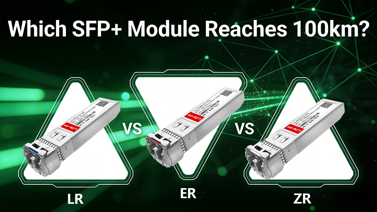
✅ 10GBASE-ZR vs. LR vs. ER: Which SFP+ Module Reaches 100km?
When engineers evaluate long-distance 10G fiber links, one of the most common questions is which SFP+ optical standard can support the required transmission distance. In 10-Gigabit Ethernet networks, three single-mode optical categories are typically considered for longer fiber spans: 10GBASE-LR, 10GBASE-ER, and 10GBASE-ZR.
While these modules share the same SFP+ form factor and 10 Gb/s data rate, they differ significantly in wavelength, optical power budget, laser technology, and maximum transmission distance. Understanding these differences is essential when determining whether a network design can realistically support distances approaching 100 km.
10GBASE-LR: Standard 10 km Single-Mode Optics
10GBASE-LR (Long Reach) is one of the most widely deployed 10G SFP+ modules in enterprise and campus networks. It operates at a 1310 nm wavelength and is designed for single-mode fiber links up to approximately 10 km.
LR optics typically use DFB (Distributed Feedback) lasers, which provide stable output power and reliable performance for medium-distance transmission. Because the required optical power budget is relatively moderate, LR modules are cost-effective and commonly used in:
data center interconnects
enterprise campus networks
metro access links
However, the 10 km reach limitation makes LR unsuitable for long-haul transmission scenarios.
10GBASE-ER: Extended Reach up to 40 km
10GBASE-ER (Extended Reach) extends the transmission distance to approximately 40 km over single-mode fiber. Unlike LR modules, ER optics operate at a 1550 nm wavelength, which benefits from lower attenuation in optical fiber.
ER modules generally require higher transmit power and more sensitive receivers to support longer distances. Many ER transceivers still use DFB lasers, but with higher optical output levels and tighter performance requirements.
Typical deployment scenarios for 10G-ER include:
metro network aggregation
inter-building fiber links
regional enterprise connectivity
service provider edge networks
Although ER significantly increases reach compared with LR, it still falls short of the 80–100 km distance range often associated with long-haul optical transport.
10GBASE-ZR: Long-Haul 10G Optics Approaching 100 km
To support much longer distances, vendors introduced 10GBASE-ZR optics, which are commonly used for 80 km to 100 km single-mode fiber links. Unlike LR and ER, ZR is not formally standardized in IEEE 802.3, but it has become widely adopted across the optical networking industry.
ZR modules typically operate at 1550 nm and use EML (Electro-Absorption Modulated Laser) technology. Compared with DFB lasers, EML lasers provide:
higher optical output power
better modulation performance at 10 Gb/s
improved tolerance to chromatic dispersion
These characteristics enable significantly higher optical link budgets, which are required to transmit signals across fiber spans approaching 100 km.
ZR optics are commonly deployed in:
long-distance metro fiber networks
regional ISP backbone links
utility and transportation communication systems
DWDM transport infrastructure
In many real deployments, ZR modules are also integrated into DWDM systems or combined with optical amplification, allowing operators to achieve stable long-distance transmission.
10GBASE-LR vs. ER vs. ZR: Distance, Lasers, and Typical Use Cases
The table below summarizes the key technical differences between these three types of 10G single-mode SFP+ optics.
Optical Standard | Wavelength | Typical Laser Type | Maximum Distance | Typical Optical Budget | Common Applications |
|---|---|---|---|---|---|
10GBASE-LR | 1310 nm | DFB | ~10 km | ~6–8 dB | Data centers, enterprise campus networks |
10GBASE-ER | 1550 nm | High-power DFB | ~40 km | ~14–16 dB | Metro aggregation, regional enterprise links |
10GBASE-ZR | ~1550 nm | EML | ~80–100 km | ~23–24 dB | Long-haul fiber, ISP backbone, DWDM transport |
This comparison clearly illustrates why ZR optics are typically required when engineers design 10G links approaching 100 km. The combination of 1550 nm wavelength, higher transmit power, and EML laser technology provides the optical budget necessary to overcome fiber attenuation over long distances.
However, distance specifications alone do not guarantee successful deployment. Fiber type, connector losses, dispersion, and network architecture can all influence whether a 100 km link is achievable without additional technologies.
In the next section, we will examine how engineers design a 100 km optical link budget, including how to calculate fiber attenuation, connector loss, and safety margins to ensure reliable 10G SFP+ long-distance transmission.
✅ How to Design a 100km Fiber Link with SFP+ Optics
Designing a 100 km optical fiber link using SFP+ transceivers requires more than simply selecting a long-reach module. Engineers must verify that the optical link budget is sufficient to overcome all signal losses along the fiber path. If the total loss exceeds the allowable budget of the optical module, the link will not operate reliably.
A typical long-distance design therefore includes four critical elements:
Optical power budget calculation
Fiber attenuation estimation
Connector and splice loss evaluation
A safety margin for real-world variability
Understanding how these factors interact is essential when evaluating whether a 10G SFP+ 100km link is technically feasible.
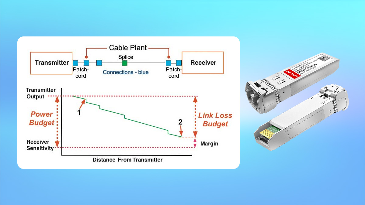
Optical Link Budget Formula
The optical link budget defines the maximum allowable signal loss between the transmitter and receiver while maintaining reliable communication.
The simplified engineering formula is:
Optical Link Budget (dB) = Transmitter Output Power (dBm) – Receiver Sensitivity (dBm)
For example, a typical 10GBASE-ZR SFP+ module might have specifications similar to:
Tx Output Power: +2 dBm to +6 dBm
Receiver Sensitivity: approximately −24 dBm
Using these values:
Link Budget ≈ 6 − (−24) = 30 dB (maximum theoretical)
In practice, vendors usually specify an effective optical budget around 23–25 dB after accounting for engineering tolerances and signal quality requirements.
This total budget must cover all attenuation across the fiber link.
Fiber Attenuation Calculation for 100 km
The largest contributor to signal loss in long-distance transmission is fiber attenuation. For standard ITU-T G.652 single-mode fiber, the attenuation at 1550 nm is typically:
0.20–0.25 dB per kilometer
A simple calculation for a 100 km fiber span would be:
Fiber Loss = Distance × Attenuation
Example:
100 km × 0.22 dB/km ≈ 22 dB fiber loss
This already consumes most of the optical budget of a typical ZR optical module, which explains why 100 km links operate very close to the physical limits of non-amplified optics.
Connector and Splice Loss
In real networks, optical fibers are rarely continuous over long distances. Fiber routes typically include multiple connectors, patch panels, and fusion splices, each introducing additional loss.
Typical values used in engineering calculations are:
Component | Typical Loss |
|---|---|
Fiber connector | 0.3–0.5 dB |
Fusion splice | 0.05–0.1 dB |
Patch panel connection | 0.3–0.5 dB |
For example, a long metro fiber route might include:
4 connectors → ~1.6 dB
10 fusion splices → ~0.7 dB
Total additional loss ≈ 2–2.5 dB
When added to fiber attenuation, the total path loss could reach:
22 dB + 2.5 dB = ~24.5 dB
This is already near the typical maximum optical budget of many 10GBASE-ZR SFP+ modules.
Engineering Safety Margin
Professional network design always includes a safety margin to ensure long-term link stability. Environmental conditions, fiber aging, connector contamination, and temperature variations can all increase optical loss over time.
A typical engineering safety margin for long-distance fiber links is:
3–5 dB
Including this margin ensures that the link continues operating reliably even as conditions change.
Example 100km Link Budget Calculation
Parameter | Example Value |
|---|---|
Fiber distance | 100 km |
Fiber attenuation (0.22 dB/km) | 22 dB |
Connector loss | 1.6 dB |
Splice loss | 0.7 dB |
Total link loss | 24.3 dB |
Recommended safety margin | 3 dB |
Required optical budget | ~27.3 dB |
This calculation demonstrates why 100 km 10G links often require additional optical technologies. In many real deployments, engineers integrate:
EDFA optical amplifiers
DWDM transport systems
dispersion compensation techniques
to increase the effective optical budget and maintain signal quality.
In the next section, we will examine SFP+ 100km Deployment Guide: Compatible Vendors, Vendor-Lock Risks, and How to Verify Compatibility while maintaining stable 10-gigabit performance.
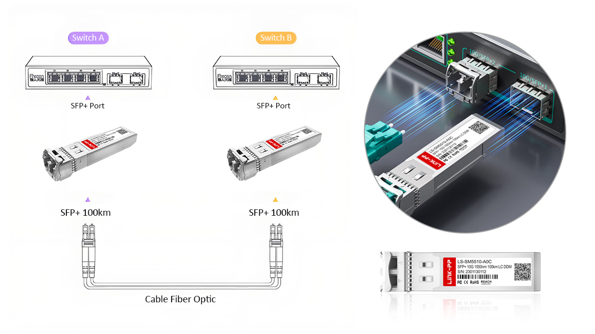
✅ SFP+ 100km Deployment: Compatibility, Vendor Lock-In, and Verification
Deploying SFP+ 100km optics in production networks requires more than selecting the correct optical reach. Long-distance modules—such as 10GBASE-ZR or DWDM SFP+ transceivers—must also be compatible with the target switch, router, or optical transport platform. In enterprise and carrier networks, vendor compatibility and firmware restrictions can directly affect whether a transceiver will operate correctly.
For this reason, engineers and procurement teams typically evaluate three practical aspects before deploying 100 km SFP+ optics:
Supported vendor platforms
Vendor lock-in mechanisms and risks
Methods to verify module recognition in network devices
Understanding these factors helps avoid unexpected interoperability issues during installation.
Common Network Platforms Supporting Long-Reach SFP+ Optics
Most modern networking equipment that supports 10G SFP+ ports can technically operate with long-reach optics, provided the module encoding matches the platform requirements.
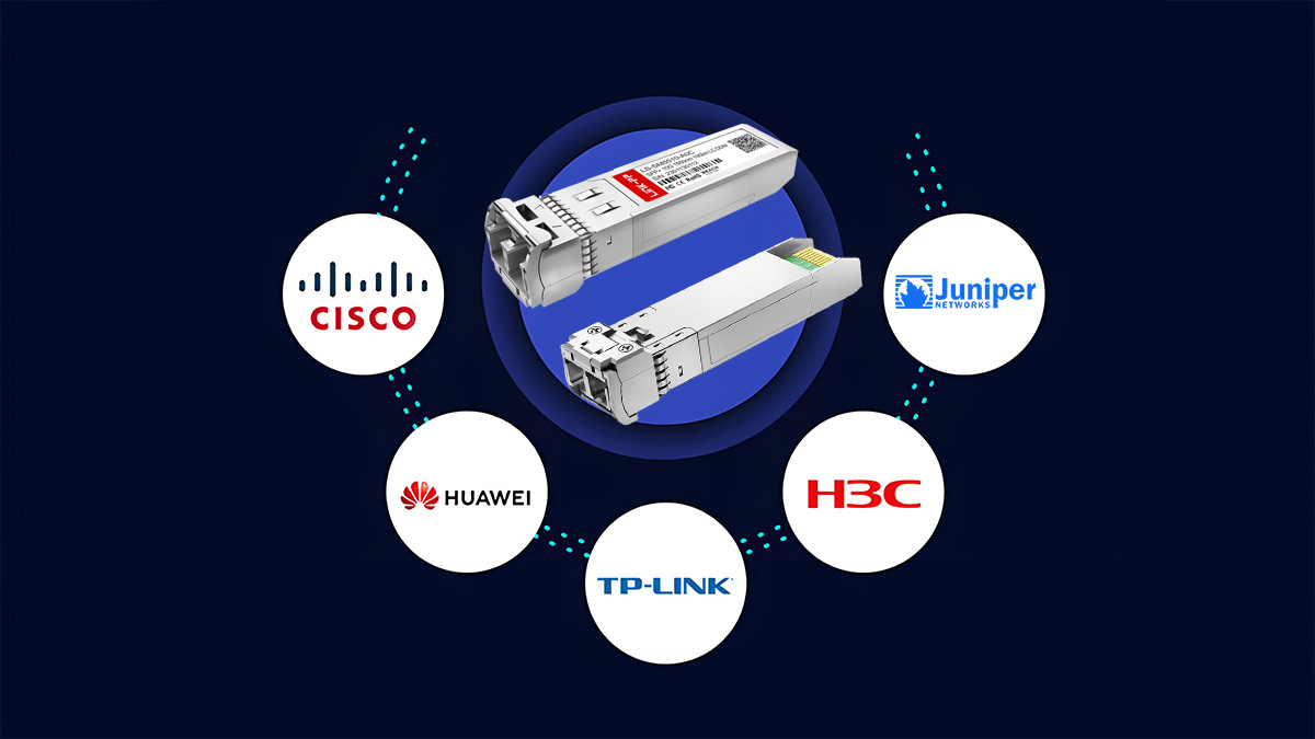
Typical compatible vendor ecosystems include:
Cisco switches and routers
Juniper Networks platforms
Arista data center switches
Huawei and ZTE carrier equipment
MikroTik and Ubiquiti network devices
In many metro or backbone networks, DWDM SFP+ modules are also deployed within:
optical transport systems
ROADM platforms
passive MUX/DEMUX DWDM networks
However, compatibility is not always guaranteed because some manufacturers implement transceiver authentication mechanisms in firmware.
Vendor Lock-In and Transceiver Authentication
Certain networking vendors implement vendor-coded transceiver identification in order to restrict the use of third-party optics. This mechanism checks the EEPROM data inside the SFP+ module, which contains information such as:
vendor name
part number
supported standards
wavelength and power parameters
If the firmware detects an unsupported module ID, the device may:
generate warning messages
disable the optical interface
restrict monitoring features such as DOM/DDM
For example, some platforms display messages similar to:
Unsupported transceiver detectedor
Third-party SFP module insertedAlthough many systems allow third-party optics, network operators often prefer vendor-coded modules to avoid compatibility warnings and ensure stable monitoring.
How to Verify SFP+ Module Compatibility on Network Devices
After installing a 100 km SFP+ transceiver, engineers typically verify recognition and operational status using command-line interface (CLI) diagnostics.
Below are several commonly used commands across different network platforms.
Cisco Example
On Cisco switches or routers, the following commands can verify module detection and operational status.
Check installed optics:
show inventoryDisplay transceiver information:
show interfaces transceiverCheck digital diagnostics monitoring (DOM):
show interfaces transceiver detailThese commands typically display parameters such as:
vendor name and part number
wavelength
transmit optical power
receive optical power
module temperature
Juniper Example
On Juniper devices running Junos OS, engineers commonly use:
show chassis hardwareto list installed transceivers.
Detailed optical diagnostics can be viewed with:
show interfaces diagnostics opticsThis command provides real-time information such as:
Tx optical power
Rx optical power
laser bias current
module temperature
These parameters are particularly important for long-distance links approaching 100 km, because monitoring optical power levels helps ensure the link remains within the required optical budget.
Best Practices for Verifying Long-Distance SFP+ Deployment
When installing 100 km SFP+ optics, network engineers typically perform several validation steps:
Confirm module recognition using platform CLI commands.
Verify wavelength and part number match the network design.
Check DOM/DDD optical power levels to confirm sufficient link margin.
Monitor alarm logs for transceiver compatibility warnings.
Test the link under production traffic loads to ensure stability.
These verification procedures help confirm that the selected SFP+ long-reach module operates correctly with the host platform and that the optical link budget remains within acceptable limits.
In the next section, we will address common engineering challenges encountered in 100 km optical deployments, including dispersion effects, optical amplification requirements, and real-world stability considerations for long-distance 10G SFP+ networks.
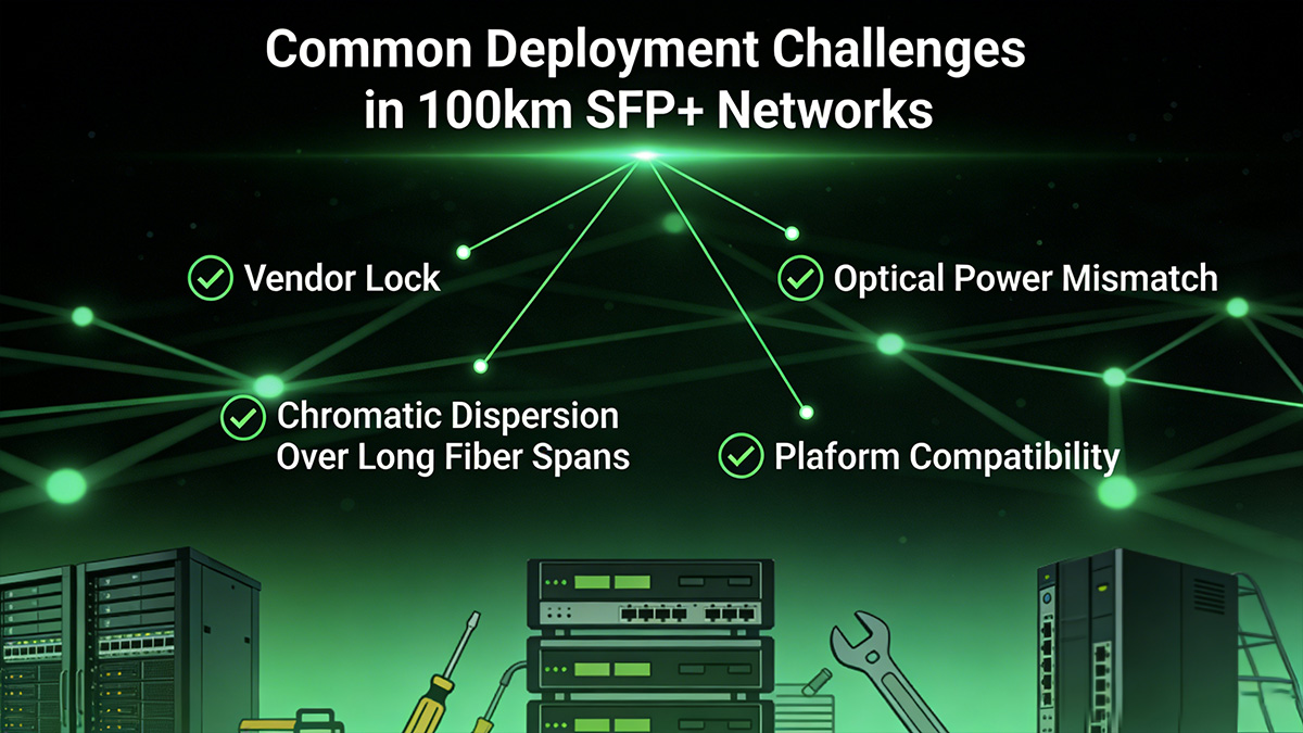
✅ Common Deployment Challenges in 100km SFP+ Networks
Although long-reach SFP+ optics such as 10GBASE-ZR make transmission distances approaching 80–100 km technically possible, real-world deployments often encounter operational challenges that prevent the link from working as expected.
Long-distance optical links operate very close to the physical limits of fiber transmission, meaning that relatively small issues—such as power imbalance, fiber dispersion, or compatibility restrictions—can prevent the link from establishing or maintaining stability.
Understanding these common challenges helps engineers diagnose problems more quickly when a 100 km SFP+ link fails to come online or shows unstable performance.
Vendor Lock and Firmware Restrictions
One of the first issues engineers may encounter is transceiver authentication enforced by network equipment vendors. Some switches and routers verify the EEPROM identification data inside the SFP+ module, which includes vendor name, part number, and supported standards.
If the module is not recognized as an approved device, the system may:
disable the interface
generate compatibility warnings
limit diagnostic monitoring features
Although many modern platforms allow third-party optics, firmware updates or strict vendor policies can sometimes prevent long-reach SFP+ modules from being accepted by the host device.
In these cases, engineers typically resolve the issue by:
using vendor-coded compatible optics
updating device firmware
verifying the module is designed for that specific platform
Optical Power Mismatch
Long-distance fiber links require careful alignment between transmit power and receiver sensitivity. A mismatch in optical power levels can prevent the link from establishing.
Two common scenarios occur:
1. Insufficient transmit power
If the transmitted optical signal is too weak after fiber attenuation, the receiver may not detect a valid signal.
2. Receiver overload
Some long-reach modules generate relatively high optical output levels. If the fiber link is shorter than expected or amplification is present, the receiver may experience optical overload, which can also prevent link establishment.
Engineers typically verify this using Digital Optical Monitoring (DOM/DDM) readings such as:
Tx optical power
Rx optical power
laser bias current
Monitoring these parameters helps confirm whether the optical signal is within the acceptable operating range.
Chromatic Dispersion Over Long Fiber Spans
Another important limitation in 100 km optical links is chromatic dispersion. As optical signals travel through fiber, different wavelengths propagate at slightly different speeds. Over long distances, this effect causes pulse broadening, which can degrade the integrity of high-speed signals such as 10 Gb/s Ethernet.
Chromatic dispersion becomes particularly significant when:
fiber spans exceed 60–80 km
older fiber types are used
transmission occurs at 1550 nm
To mitigate dispersion, network designers may use:
dispersion-tolerant optics (EML-based modules)
dispersion compensation modules (DCM)
DWDM transport systems with dispersion management
Platform Compatibility and Interoperability Issues
Even when optics are physically supported by a device, interoperability between different vendors can still cause operational issues.
Common compatibility challenges include:
mismatched wavelength specifications
incompatible digital diagnostics monitoring (DOM) implementation
unsupported optical power ranges
differences in transceiver firmware encoding
These issues are more likely to appear in long-distance optics, where stricter optical tolerances are required.
Before deploying SFP+ 100km modules, engineers typically verify compatibility through:
vendor compatibility matrices
optical specification comparison
interoperability testing in a lab environment
Troubleshooting: Top 10 Reasons a 100 km SFP+ Link Won’t Come Up
When a long-distance SFP+ fiber link fails to establish, the root cause is usually related to optical budget limitations, configuration mismatches, or hardware compatibility problems. The following checklist summarizes the most common issues encountered in 100 km deployments.
# | Possible Cause | Explanation |
|---|---|---|
1 | Insufficient optical power budget | Total fiber loss exceeds module capability |
2 | Incorrect optical module type | Using LR or ER optics instead of ZR |
3 | Fiber attenuation too high | Older fiber or poor-quality cable increases loss |
4 | Excessive connector or splice loss | Too many connection points in the fiber path |
5 | Chromatic dispersion effects | Signal distortion over long fiber distances |
6 | Vendor lock or unsupported optics | Switch firmware blocks third-party modules |
7 | Optical receiver overload | Signal power too strong for receiver tolerance |
8 | Wavelength mismatch | Incorrect DWDM channel or optical specification |
9 | Fiber polarity issues | TX and RX fibers reversed |
10 | Dirty or damaged fiber connectors | Contamination causes unexpected signal loss |
When troubleshooting long-distance fiber links, engineers typically start by verifying optical power levels using DOM monitoring and confirming that the total link loss remains within the module’s optical budget.
Because 100 km transmission operates near the limits of 10G optical technology, careful fiber inspection, accurate link budget calculations, and compatible optical modules are essential for achieving stable long-distance connectivity.
✅ Real-World Engineer Insights on 100km Optical Links
While datasheets define the theoretical reach of 100km Transceiver, real-world deployments often reveal additional engineering considerations that are rarely documented in product specifications. Insights from field engineers and network operators provide valuable lessons about long-distance optical design, stability, and troubleshooting.
This section summarizes practical deployment experiences reported by engineers across networking communities and operational environments.
1. Long-Distance Links Often Require Careful Optical Power Validation
A common issue in long-haul fiber deployments is unexpected optical power mismatch between transmitter and receiver.
In practice, engineers frequently observe link failures where the receiver reports extremely low optical input power (for example −35 dBm or lower), which typically indicates no detectable signal or severe attenuation. In troubleshooting discussions, engineers often recommend verifying real-time optical diagnostics using CLI commands before replacing hardware.
Typical diagnostic commands include:
show interfaces transceiver details
show interfaces diagnostics optics
ethtool -m ethX
These commands allow engineers to confirm:
TX optical power
RX optical power
laser bias current
module temperature
Monitoring these parameters helps determine whether the issue is related to fiber attenuation, connector contamination, or incompatible optics.
2. Fiber Quality and Termination Strongly Affect 10G Long-Distance Links
In real deployments, poor fiber termination can prevent a 10G optical link from establishing even if shorter-distance links work correctly.
Engineers frequently encounter cases where:
1G optics link successfully
10G optics fail to establish a link
This often occurs because 10 Gbps signals have tighter optical power and dispersion tolerances. In one troubleshooting example, both modules reported approximately −40 dBm receive power, suggesting either fiber loss or poor termination quality.
Typical causes include:
Excessive splice loss
Dirty connectors
Poor polishing quality
Micro-bending in long fiber routes
For 100 km deployments, even small additional losses can break the link budget.
3. 100 km Optics Typically Use Advanced Laser and Receiver Designs
Long-haul SFP+ optics generally use higher-performance optical components compared with short-reach modules.
Typical architecture of a 10GBASE-ZR-class module:
Laser type: EML (Electro-Absorption Modulated Laser)
Wavelength: ~1550 nm
Receiver: APD photodiode
Reach: up to ~100 km over OS2 fiber
These components enable:
higher launch power
improved receiver sensitivity
better dispersion tolerance
However, these modules are also more sensitive to link engineering mistakes, such as incorrect attenuation planning.
4. Real Deployments Often Use Metro or DWDM Architectures
In many real-world networks, 100 km SFP+ links are rarely deployed as simple point-to-point connections.
Instead, operators commonly integrate them into:
metro transport networks
DWDM systems
carrier aggregation rings
Typical architecture:
Data Center A
   │
10G ZR SFP+
   │
Metro Dark Fiber (OS2 SMF)
   │
DWDM / OADM (optional)
   │
10G ZR SFP+
   │
Data Center B
This architecture allows multiple wavelengths to share the same fiber infrastructure, significantly improving scalability.
5. Engineers Recommend Extensive Pre-Deployment Testing
Experienced network engineers often emphasize lab validation before production deployment, especially for long-distance optics.
Common best practices include:
Validate optics compatibility with the switch platform.
Measure fiber attenuation using OTDR or optical power meters.
Confirm optical power budget under real conditions.
Test both directions of the link before final installation.
Many engineers also stress the importance of cleaning all fiber connectors, as contamination is one of the most common causes of link instability in optical networks.
Key Takeaways from Field Engineers
Real-world experiences consistently highlight several lessons:
Fiber quality matters as much as optics.
Optical power budgets must include safety margins.
Vendor compatibility should be validated early.
Monitoring diagnostics is essential for troubleshooting.
While datasheets may specify 100 km reach, reliable deployment ultimately depends on careful link engineering and validation.
✅ SFP+ 100km FAQs
Below are common questions network engineers ask when designing or purchasing 100 km SFP+ optical links.
Q1. Can an SFP+ transceiver reach 100 km?
Yes — but only specific long-reach optics such as 10GBASE-ZR can support distances approaching 100 km.
Typical reach classes:
Module Type | Typical Reach | Wavelength | Fiber |
|---|---|---|---|
10GBASE-LR | 10 km | 1310 nm | SMF |
10GBASE-ER | 40 km | 1550 nm | SMF |
10GBASE-ZR | 80–100 km | 1550 nm | SMF |
ZR-class optics use high-power lasers and more sensitive receivers to extend transmission distance beyond standard Ethernet specifications.
However, the actual distance depends on:
connector and splice loss
chromatic dispersion
system margin
A module labeled “100 km” indicates an optical budget target, not a guaranteed distance.
Q2. What is the difference between 10G-LR (10 km) and 10G-ZR (100 km)?
The primary differences are distance capability, laser type, and optical budget.
Parameter | 10GBASE-LR | 10GBASE-ZR |
|---|---|---|
Reach | 10 km | 80–100 km |
Wavelength | 1310 nm | 1550 nm |
Laser Type | DFB | High-power DFB / EML |
Receiver | PIN | APD |
Fiber Type | SMF | SMF |
Typical Applications | Data center interconnect | Metro or regional links |
ZR modules operate in the 1550 nm optical window, where fiber attenuation is lowest (~0.2 dB/km).
Q3. Do I need DWDM or ZR optics to run a 100 km SFP+ link?
Yes. Standard Ethernet optics like LR (10 km) or ER (40 km) cannot support 100 km transmission.
You typically need:
10GBASE-ZR optics (for simple point-to-point links)
DWDM ZR optics (for multi-channel metro networks)
Many ZR modules operate at 1550 nm with narrow-linewidth lasers, enabling long-distance transmission and compatibility with DWDM infrastructure.
Q4. How do I calculate the optical budget for a 100 km link?
Optical link design is based on total loss vs. module optical budget.
Basic formula
Total Link Loss = Fiber Loss + Connector Loss + Splice Loss + MarginTypical example for a 100 km link:
Component | Calculation | Loss |
|---|---|---|
Fiber attenuation | 100 km × 0.20 dB/km | 20 dB |
Connectors | 2 × 0.5 dB | 1 dB |
Splices | 10 × 0.1 dB | 1 dB |
Safety margin | — | 3 dB |
Total link loss ≈ 25 dB
If the ZR module has a 30 dB optical budget, the link should operate reliably.
Q5. Do I need optical amplifiers (EDFA) for a 100 km SFP+ link?
Not always.
Amplifiers are only required when total span loss exceeds the module optical budget.
A 100 km link may operate without amplification if:
fiber attenuation ≈ 0.20 dB/km
minimal connectors/splices
adequate system margin
However, in metro or DWDM networks, engineers often deploy:
EDFA (Erbium-Doped Fiber Amplifier)
DCM (Dispersion Compensation Module)
These help maintain signal integrity across longer spans.
Q6. Will my switch accept third-party 10G ZR (100 km) SFP+ modules?
It depends on the switch vendor.
Most enterprise switches support SFP+ MSA-compliant optics, but some vendors implement vendor lock mechanisms that restrict third-party modules.
Common behaviors:
Vendor | Third-Party Support |
|---|---|
Cisco | Often restricted unless compatibility-coded |
Juniper | Usually supported with vendor coding |
Huawei | Compatible optics commonly used |
Arista | Generally open |
Some switches allow commands such as:
service unsupported-transceiver
no errdisable detect cause gbic-invalid
These commands enable non-OEM optics, but support policies may vary.
Q7. Will third-party 100 km SFP+ work in Cisco, Juniper, or Huawei switches?
Yes — in many cases.
Most third-party optics are MSA compliant and vendor-coded, meaning they emulate OEM modules electronically.
Compatibility depends on:
EEPROM vendor coding
firmware restrictions
power consumption limits
supported reach types
Testing in the target platform is strongly recommended.
Q8. Which 100 km SFP+ vendors are commonly used?
Many manufacturers produce ZR-class SFP+ modules using high-quality optical components.
Typical ecosystem:
Component | Typical Suppliers |
|---|---|
Laser chip | Broadcom, Lumentum |
Receiver | APD photodiode vendors |
Module vendors | Finisar, II-VI, FS, OEM-coded vendors |
Most modules use:
1550 nm cooled EML transmitters
APD receivers
DOM/DDM diagnostics
These components allow reliable operation over up to ~100 km of single-mode fiber.
Q9. Can a 100 km SFP+ link work without DWDM infrastructure?
Yes.
For simple point-to-point links, a ZR SFP+ module can run over:
OS2 single-mode fiber
duplex LC connectors
1550 nm wavelength
DWDM infrastructure becomes necessary when:
multiple wavelengths share one fiber
amplification is required
long metro transport networks are deployed.
✅ Conclusion: Choosing the Right SFP+ 100km Optics for Reliable Long-Distance Links
Designing a 100 km optical Ethernet link requires more than simply selecting a long-reach transceiver. Engineers must evaluate multiple factors—including optical power budget, fiber attenuation, dispersion tolerance, connector loss, and platform compatibility—to ensure stable long-distance transmission.
For most deployments, 10GBASE-ZR SFP+ optics operating at 1550 nm are the practical solution for reaching distances close to 80–100 km over single-mode fiber (SMF). Compared with standard 10GBASE-LR (10 km) and 10GBASE-ER (40 km) modules, ZR optics provide significantly higher optical budgets and often incorporate high-power transmitters and sensitive APD receivers to overcome fiber attenuation.
However, real-world link performance still depends on careful planning:
Calculate the optical budget to confirm the link margin.
Verify switch compatibility and avoid vendor-lock issues.
Account for connector, splice, and dispersion losses in long spans.
Consider EDFA amplification or DWDM infrastructure if the fiber path approaches system limits.
When properly designed, SFP+ 100 km links provide a cost-effective solution for metro connectivity, long-distance campus interconnects, and regional network backbones, without requiring complex coherent transport systems.

Source Reliable 100km SFP+ Optics
If you are deploying long-distance 10 GbE networks, selecting high-quality optical components is essential for ensuring signal stability and compatibility with major switching platforms.
At LINK-PP, engineers and network integrators can find a range of SFP+ long-reach optical modules and fiber connectivity solutions designed for enterprise, telecom, and industrial networking environments.
✔ High-performance 10G long-reach optics
✔ Compatible with major platforms (Cisco, Juniper, Huawei, Arista)
✔ Strict quality control and industry-standard compliance
✔ Suitable for metro, ISP, and long-distance backbone networks
👉 Explore the full product catalog at the LINK-PP Official Store to find the right SFP+ 100 km optical solution for your next network deployment.


