
📘 Introduction
High-speed networking requires robust and standardized electrical interfaces to ensure reliable 40 Gb/s links between host ASICs and pluggable optical modules. One critical interface in this domain is the 10-lane Attachment Unit Interface (XLAUI), defined in the IEEE 802.3ba standard. Engineers, system architects, and module integrators deploying 40G QSFP+ modules benefit from a clear understanding of XLAUI to ensure interoperability, signal integrity, and predictable performance.
This article explains what XLAUI is, how it operates, why it matters in 40G QSFP+ modules, and provides practical insights using LINK-PP 40G QSFP+ modules as real-world examples.
📘 What is XLAUI?
XLAUI stands for eXtended 10-Lane Attachment Unit Interface. It is an electrical interface defined in IEEE 802.3ba for 40 Gigabit Ethernet (40GbE). XLAUI is used for chip-to-module or chip-to-chip connections, particularly in pluggable modules like QSFP+.
Key characteristics:
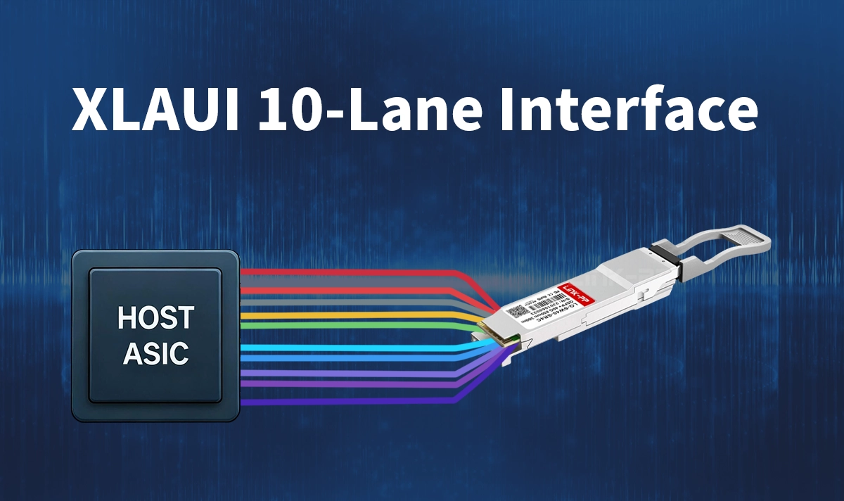
Lane structure: 10 parallel lanes, each operating at ~10.3125 Gb/s, aggregating to ~40 Gb/s of user data after encoding.
Applications: Host-to-module links for optical or copper backplanes.
Electrical standards: Defined in Annex 83A of IEEE 802.3ba, including transmitter/receiver parameters, channel loss budgets, return loss, and jitter budgets.
Relationship to other AUIs: Part of the "Attachment Unit Interface" family—like XAUI (10GbE) or CAUI (100GbE), but optimized for 40GbE.
XLAUI allows for manageable lane speeds while achieving high aggregate bandwidth, making it practical for dense switch and server designs.
📘 How XLAUI Works
▷ Lane Structure & Data Rate
Each of the 10 lanes carries ~10.3125 Gb/s.
After 64b/66b encoding, aggregate user data rate reaches ~40 Gb/s.
▷ SERDES Operation
Each lane uses a Serializer/Deserializer (SERDES) to convert parallel data to serial streams and vice versa.
Modules or retimers may use a gearbox to map 10 electrical lanes into fewer optical lanes (e.g., 10→4 mapping).
▷ Channel Requirements
IEEE 802.3ba specifies channel loss, return loss, jitter, and skew limits.
Example: ~10 dB loss allowed at Nyquist frequency (~5.15625 GHz) for typical 250 mm FR4 PCB traces.
▷ Chip-to-Module vs Chip-to-Chip
XLAUI is primarily a chip-to-module interface (ASIC → QSFP+).
Can also support backplane or PCB interconnects with proper signal integrity management.
📘 Importance of XLAUI in 40G QSFP+ Modules
1. Higher Port Density
Multiple ~10 Gb/s lanes are easier to route than a single ultra-high-speed lane.
Enables compact QSFP+ form factors and high-density linecards.
2. Standardized Compatibility
Standardization allows module and ASIC vendors (e.g., LINK-PP) to design to a common interface.
Interoperability is improved across multi-vendor systems.
3. Manageable Signal Integrity
Moderate lane speeds simplify PCB design, hot-plug connector implementation, and reduce retimer requirements.
4. Future-Proofing
XLAUI remains relevant for legacy 40G modules and mixed-rate fabrics, even with emerging 25G/50G lane technologies.
LINK-PP 40G QSFP+ Modules and XLAUI
Example: LINK‑PP LQ‑CW40‑LR4C 40G QSFP+ module
Converts 4×10 Gb/s electrical lanes into 4 CWDM optical signals.
Compatible with IEEE 802.3ba electrical interface standards, effectively implementing XLAUI-like 10-lane operation on the host side.
Design implications:
Host ASIC or switch must support a 10-lane XLAUI interface.
PCB design must ensure signal integrity, lane alignment, and skew control.
Confirm vendor compatibility for electrical interface adherence.
LINK-PP modules adhere to IEEE standards, enabling predictable performance and simplified integration in 40G systems.
📘 Design Considerations & Best Practices
Lane skew control: Ensure lane-to-lane skew is within specification for proper SERDES/gearbox alignment.
Jitter budget: Follow IEEE transmitter/receiver jitter masks (Annex 83A).
Channel loss budget: Typical ~10 dB loss at Nyquist frequency for ~250 mm FR4 traces.
SERDES calibration: Implement pre-emphasis, CTLE, and DFE as required.
Module compatibility: Verify host interface and QSFP+ form factor alignment.
Future-proofing: Plan for 100G (CAUI-10) or 400G systems with lane breakout flexibility.
📘 Summary
XLAUI (10-Lane Attachment Unit Interface) is a critical electrical interface standard for 40GbE systems. By splitting 40G into ten ~10.3 Gb/s lanes, it enables modular, high-density, and interoperable QSFP+ deployments. Engineers integrating LINK-PP 40G QSFP+ transceivers must understand XLAUI to ensure proper PCB design, SERDES configuration, and reliable data-center performance.
📘 FAQ
1. What is the primary purpose of XLAUI?
XLAUI provides a standardized 10-lane electrical interface between a host ASIC (or PHY) and a 40G QSFP+ module. It enables reliable 40 Gb/s data transfer while maintaining manageable lane speeds (~10.3125 Gb/s) for signal integrity and PCB routing.
2. How does XLAUI differ from XAUI or CAUI?
XAUI: 4 lanes for 10GbE (~3.125 Gb/s per lane after encoding).
XLAUI: 10 lanes for 40GbE (~10.3125 Gb/s per lane).
CAUI: 10 or 20 lanes for 100GbE (~10–25 Gb/s per lane).
XLAUI balances higher aggregate bandwidth with moderate per-lane speeds to simplify system design.
3. Can XLAUI be used for backplane connections?
Yes. While primarily designed for chip-to-module links (ASIC → QSFP+), XLAUI can support backplane or PCB interconnects if channel loss, skew, and signal integrity requirements are met.
4. What is the role of SERDES and gearbox in XLAUI?
SERDES: Converts parallel data to serial streams (and vice versa) on each of the 10 lanes.
Gearbox (optional): Maps multiple electrical lanes to fewer optical lanes inside the module (e.g., 10 electrical → 4 optical lanes) while maintaining alignment.
5. Are all 40G QSFP+ modules XLAUI-compliant?
Not all. Some modules use alternative 4-lane electrical interfaces like XLPPI or XLAUI-4. Always check the module datasheet for lane count, electrical interface type, and host compatibility.
6. How do I ensure proper lane alignment and signal integrity?
Control lane-to-lane skew within IEEE specifications.
Adhere to channel loss and jitter budgets.
Use SERDES features such as pre-emphasis, CTLE, and DFE as recommended.
Validate PCB routing, connector, and retimer performance.
7. Why is XLAUI still relevant in modern networks?
Despite newer 25G or 50G lane technologies, XLAUI remains widely used for legacy 40G deployments, high-density QSFP+ designs, and mixed-rate data center fabrics. It provides interoperability and a known electrical performance baseline.
8. How does LINK-PP implement XLAUI in their 40G QSFP+ modules?
LINK-PP’s 40G QSFP+ modules (e.g., LQ-CW40-LR4C) follow IEEE 802.3ba standards and implement electrical lanes equivalent to XLAUI for host-side connections. This ensures predictable performance and easier integration into switches or linecards supporting 10-lane XLAUI.
9. What design considerations should engineers keep in mind when deploying XLAUI?
Verify host ASIC supports 10-lane XLAUI.
Ensure channel insertion loss, return loss, and crosstalk meet standards.
Align SERDES lanes properly to avoid errors.
Consider thermal and power constraints in dense deployments.
Plan lane breakout paths for future upgrades (e.g., 100G or 400G).
10. Can XLAUI interfaces be upgraded to higher speeds in the future?
Yes, but it requires careful planning. Future upgrades to CAUI or other higher-lane architectures may affect PCB routing, retimer requirements, and SERDES allocation. Proper design foresight ensures backward compatibility with 40G QSFP+ modules.
