


High-speed communication systems—from Ethernet switches to optical transceivers—depend on an internal technology that most engineers use every day but rarely see directly: SERDES, short for Serializer/Deserializer. As data rates scale from 10G to 800G, SERDES has become a foundational building block that enables reliable transmission over high-speed electrical and optical links.
This article provides a clear, technically accurate overview of SERDES architecture, how it works, and where it is used, following authoritative sources such as IEEE 802.3 standards and modern high-speed I/O design principles.
Key Takeaways
SERDES technology converts parallel data into a high-speed serial data stream, enabling efficient data transfer between devices.
Using SERDES reduces the number of lines required for communication, simplifying board design and lowering costs.
SERDES enhances signal integrity through differential signaling, minimizing noise and electromagnetic interference.
This technology supports high-speed applications in data centers, automotive systems, and advanced computing, meeting the ever-increasing demands for high-speed data transmission.
Understanding SERDES helps you design more reliable and efficient systems, thereby improving overall performance in high-speed environments.
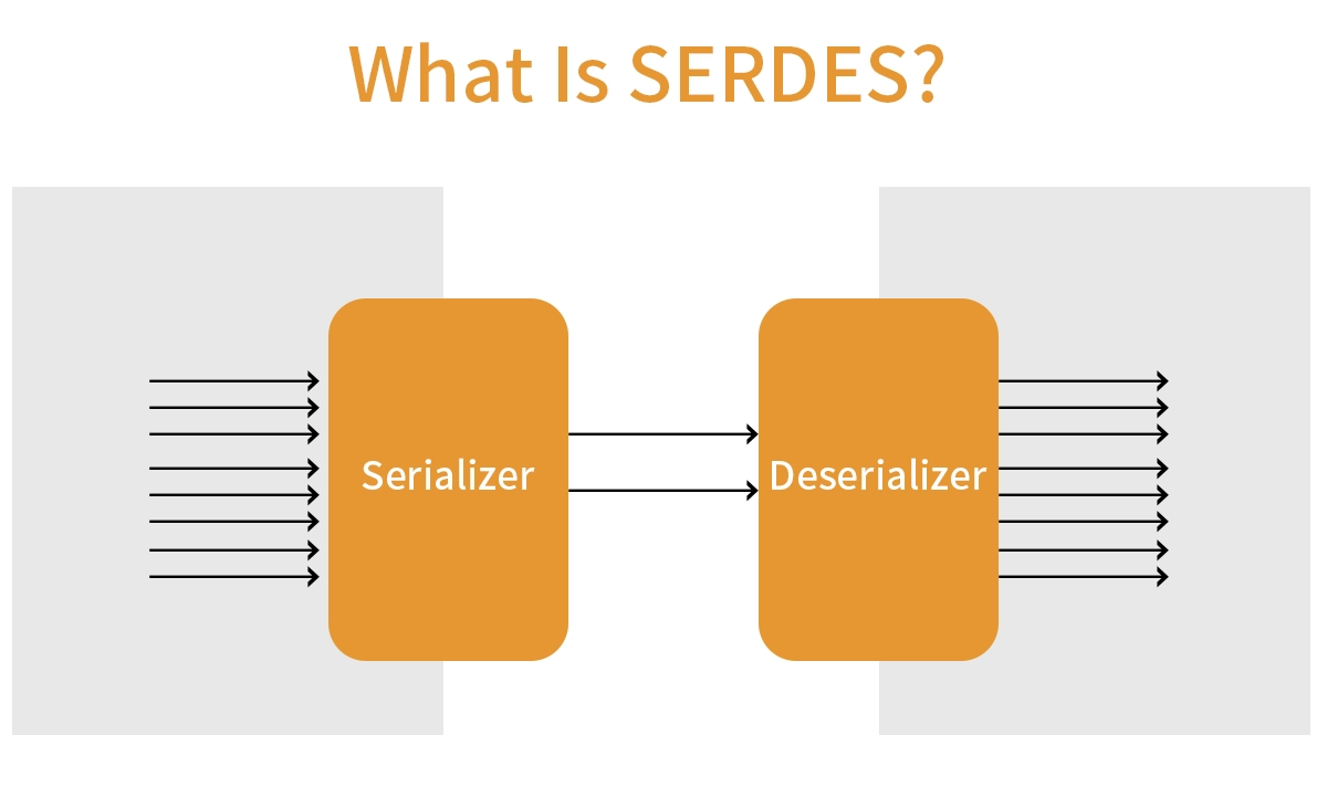
1. What Is SERDES?
A SERDES (Serializer/Deserializer) is a high-speed interface circuit that converts parallel data into serial data for transmission, then reconstructs it back to parallel data on the receiving side.
Its core purpose is to support high-bandwidth communication while minimizing pin count, skew, and signal integrity issues.
Instead of using wide parallel buses—which require dozens of traces and create large skew budgets—SERDES transmits data over one or a few high-speed differential lanes. This reduces board complexity and enables much higher throughput.
2. Why SERDES Matters in High-Speed Data Transmission
Modern systems must support massive bandwidth with low power, low latency, and high signal integrity. SERDES addresses key limitations of traditional parallel interfaces:
Parallel Buses Limitations
Require many I/O pins
Complex PCB routing
Severe clock skew at multi-GHz rates
Advantages of SERDES
Uses fewer differential pairs
Supports multi-gigabit transmission
Enables longer reach on PCB, backplane, and fiber
Integrates advanced equalization and CDR
Reduces overall system power and cost
This is why SERDES is used in nearly all high-speed standards, including Ethernet, PCIe, CPRI/eCPRI, JESD204C, and optical modules like SFP+ and QSFP+.
3. How a SERDES Works (Architecture Overview)
A SERDES link consists of a transmitter (TX) and receiver (RX) with several essential functional blocks.
3.1 Transmitter Path
Parallel Input (e.g., 8, 16, 32 bits)
Serializer
Encoding (8b/10b, 64b/66b, or PAM4 modulation)
Pre-emphasis / Equalization
High-speed serial output over a differential pair
3.2 Receiver Path
High-speed serial input
Equalization (CTLE/DFE/FIR filters)
Deserializer
Parallel output to the host IC
Together, these allow transmission at 10G, 25G, 50G, 112G PAM4, and beyond.
4. SERDES Inside QSFP+ Optical Transceivers
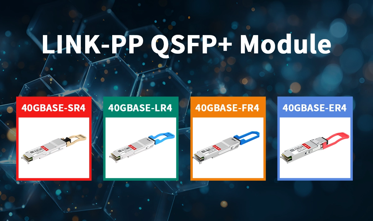
40G QSFP+ transceivers such as LINK-PP LQ-SW40-SR4C rely heavily on SERDES technology internally.
According to the IEEE 802.3ba standard, a QSFP+ module uses:
4 × 10.3125 Gbps electrical SERDES lanes
Defined by the XLPPI (40G Extended Four-Lane Parallel Physical Interface)
Mapped to 4 optical lanes for 40GBASE-SR4
SERDES roles inside the module
Converts host electrical SERDES lanes into optical modulation
Manages CDR for each lane
Ensures link stability across temperature and voltage variations
Works with parallel optics for short-range fiber connections
Because of this, SERDES performance defines the module’s signal integrity, jitter tolerance, and overall link quality.
5. Common SERDES Applications
Application Type | SERDES-Based Standards |
|---|---|
Data Center Ethernet | 10G/25G/40G/100G/400G Ethernet |
SFP+, QSFP+, QSFP28, QSFP-DD | |
Backplane & Chip-to-Chip | PCI Express, SAS/SATA |
Telecom / Wireless | CPRI, eCPRI, Radio Units |
JESD204B / JESD204C |
Any system moving data at multi-gigabit speeds relies on a SERDES somewhere in its signal path.
6. Summary
SERDES is one of the most critical technologies in modern networking. By enabling efficient high-speed serial transmission, it serves as the backbone of Ethernet optical modules, data center switching fabrics, chip-to-chip links, and next-generation communication systems.
Products like LINK-PP’s LQ-SW40-SR4C QSFP+ module rely on advanced SERDES design to deliver stable 40G performance with excellent interoperability and long-term reliability.
7. FAQ
♦ What does SERDES stand for?
SERDES stands for Serializer/Deserializer. You use it to convert parallel data into serial data for transmission and then back to parallel data at the receiver.
♦ What is the main advantage of using SERDES?
You reduce the number of wires and pins needed for high-speed data transfer. This makes your circuit boards simpler and improves signal quality.
♦ What types of encoding do SERDES interfaces use?
You often see encoding schemes like 8b/10b, 64b/66b, and PAM4. These help you maintain data integrity and support clock recovery.
♦ What applications use SERDES technology?
You find SERDES in data centers, optical modules, chip-to-chip links, and high-speed interfaces like Ethernet and PCI Express.
♦ What is differential signaling in SERDES?
Differential signaling uses two wires for each signal. You get better noise immunity and lower electromagnetic interference, which helps your data stay reliable.
See Also
The Importance of Digital Monitoring in Optical Transceivers
Key Differences Between Single Fiber and Dual Fiber Transceivers
Essential Terminology for Understanding Optical Transceivers


