
The Physical Coding Sublayer (PCS) is a critical component of the Ethernet Physical Layer (PHY), sitting between the Reconciliation Sublayer (RS) and the Physical Medium Attachment (PMA). Its core responsibility is to transform digital data into a format that can be reliably transmitted over copper or optical media—even at extremely high speeds such as 10G, 25G, 40G, 100G, and beyond.
The PCS has evolved significantly through IEEE 802.3 amendments, supporting increasingly complex coding schemes to ensure synchronization, error detection, and transmission efficiency across modern networks.
➡️ What Is the PCS in Ethernet?
The Physical Coding Sublayer defines the encoding, decoding, alignment, and control mechanisms required before signals are serialized and sent to the PMA. It ensures that binary data from higher layers is properly structured for the electrical or optical medium.
In simple terms, the PCS prepares data for transport.
➡️ Key Functions of the PCS
1. Line Coding and Block Encoding
The PCS implements specific encoding schemes depending on the Ethernet generation:
8B/10B coding for early Gigabit Ethernet
64B/66B coding for 10G/25G/40G/100G Ethernet
256B/257B coding for advanced architectures like 200G/400G
These encoding blocks ensure:
Sufficient signal transitions for clock recovery
Balanced DC characteristics
Control symbol insertion
Error detection capabilities
64B/66B is the dominant scheme in high-speed optics due to low overhead and high efficiency.
2. Synchronization & Alignment Markers
High-speed links require the receiver to maintain bit and frame alignment.
The PCS provides:
Block synchronization
Alignment markers (especially for multi-lane systems like 40GBASE-R, 100GBASE-R)
Lane deskewing across parallel optical lanes
Without PCS alignment logic, multi-lane Ethernet would not support deterministic, stable data transfer.
3. Error Detection and Idle Control
The PCS layer adds structure that enables:
Error checking via block validity
Idle insertion for link management
Ordered sets for link negotiation (e.g., “Local Fault”, “Remote Fault”)
The PCS, therefore, not only formats data—it also supports link health monitoring.
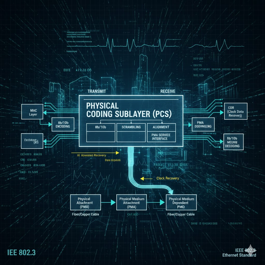
➡️ PCS vs PMA vs PMD — How They Work Together
PCS → PMA → PMD Overview
Layer | Function |
|---|---|
PCS(Physical Coding Sublayer) | Coding, alignment, lane distribution |
PMA (Physical Medium Attachment) | Serialization/deserialization, scrambling |
Defines optical/electrical media, wavelengths, and modulation |
The PCS prepares digital blocks.
The PMA serializes the bits.
The PMD interacts with the physical medium, such as fiber, copper, or backplane.
➡️ Why PCS Matters in Modern Optical Transceivers
High-speed optical modules—such as SFP+, SFP28, QSFP+, QSFP28, QSFP56—depend on PCS functions for interoperability across switches, routers, and data center equipment.
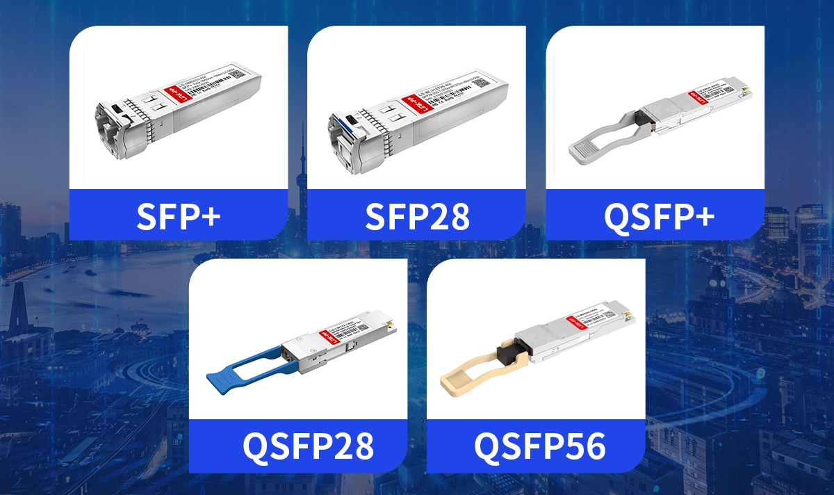
Key reasons PCS is essential in optical transceivers:
1. Ensuring Low BER (Bit Error Rate)
Efficient block encoding and alignment reduce transmission errors and increase link reliability.
2. Supporting Multi-Lane Architectures
40GBASE-R and 100GBASE-R rely heavily on PCS lane striping and deskew logic.
3. Enabling Higher Port Density
Encoding efficiency (e.g., 64B/66B) minimizes overhead, allowing more bandwidth per lane.
4. Related LINK-PP Products
LINK-PP provides a wide range of optical transceivers that operate with IEEE PCS-based Ethernet standards, including:
40G/100G QSFP+ / QSFP28 Modules
These modules are designed for compatibility, low BER performance, and stable operation across PCS-based Ethernet PHYs.
➡️ PCS in Different Ethernet Standards
▷ PCS in 10 Gigabit Ethernet (10GBASE-R)
Uses 64B/66B encoding
Defines block lock and marker detection
Optimized for long-reach optical transmission
▷ PCS in 25G Ethernet (25GBASE-R)
Retains 64B/66B
Adds improved FEC (Forward Error Correction) integration
▷ PCS in 40G/100G Ethernet (40GBASE-R / 100GBASE-R)
Introduces lane multiplexing with alignment markers
Critical for maintaining stability across parallel fiber channels
▷ PCS in Beyond-100G Architectures
IEEE 802.3bs and 802.3cd enhancements introduce:
Higher block sizes
PAM4 modulation (handled at PMA/PMD but coordinated with PCS)
➡️ Applications Where PCS Plays a Critical Role
● Data Centers
High-throughput spine-leaf networks rely on PCS for lossless communication between switches.
● Carrier & Metro Ethernet
PCS helps maintain signal integrity across long-reach optical links.
● Industrial Ethernet
Stable PCS coding is essential for deterministic traffic in harsh environments.
➡️ Conclusion
The Physical Coding Sublayer (PCS) is a foundational element of Ethernet PHY architecture, enabling reliable data encoding, synchronization, and alignment across both copper and optical transmission. As data rates scale to 100G, 200G, and 400G, PCS continues to evolve, supporting advanced coding schemes and multi-lane designs.
For system integrators, data center engineers, and OEMs, understanding PCS helps ensure the correct selection of transceivers, PHY components, and networking equipment—ultimately improving link performance, interoperability, and overall network reliability.


