

The Physical Medium Dependent (PMD) sublayer is one of the most important elements of the Ethernet physical layer, yet it is often misunderstood. PMD defines how bits are physically transmitted and received over a specific medium—single-mode fiber, multimode fiber, direct-attach copper, or electrical backplane.
For network designers, test engineers, and procurement teams, understanding PMD is essential because PMD specifications directly influence interoperability, reach, signal integrity, and transceiver selection.
This guide provides a professional, standards-aligned explanation of PMD, including the parameters you must evaluate when selecting optical transceivers such as SFP, SFP+, and QSFP modules.
➡️ What Is the Physical Medium Dependent (PMD) Sublayer?
The Physical Medium Dependent (PMD) sublayer is the lowest functional block of the IEEE 802.3 PHY. It defines the optical or electrical characteristics required for successful transmission across the chosen medium.
In real products, PMD corresponds to the front-end interface of an optical transceiver—its laser, receiver photodiode, modulation circuitry, and related components.
What PMD controls
The optical wavelength and spectral width
Transmit (Tx) average power and launch conditions
Receiver (Rx) sensitivity and overload limits
Optical return loss and extinction ratio
Supported fiber type and link distance
Electrical transmit/receive eye masks (for electrical PHYs)
Test point definitions for compliance measurements
PMD acts as the bridge between the standardized PHY logic and the physical world, ensuring that multiple vendors’ transceivers interoperate on the same fiber plant.
➡️ PMD vs. Other PHY Sublayers
Ethernet PHY architecture typically includes:
PCS (Physical Coding Sublayer) — encoding, 64b/66b, FEC, and lane distribution
PMA (Physical Medium Attachment) — serialization/deserialization, clock recovery
PMD (Physical Medium Dependent) — medium-specific optical/electrical parameters
PMD is the portion directly tied to the optical budget and medium type.
A single MAC may support multiple PMDs (e.g., SR, LR, ER), each optimized for a different reach or medium.
➡️ Why PMD Matters in Real Networks

1. Guaranteed Interoperability
Only modules conforming to the same PMD specifications will reliably link up. Wavelength, power levels, and sensitivity must align with IEEE requirements.
2. Predictable Link Reach
PMD parameters define the link-loss budget. If a module specifies a Tx power of –3 dBm to +3 dBm and an Rx sensitivity of –14 dBm, the usable optical budget is built from these numbers.
3. Accurate Testing and Compliance
PMD defines standardized test points (e.g., TP2, TP3), ensuring that optical power, jitter, and eye diagrams are measured consistently.
4. Reliability Over Time
Modules with stronger PMD margins tolerate aging, temperature variation, fiber contamination, and connector reflections better than modules built to minimum requirements.
➡️ Key PMD Parameters You Must Evaluate
Each PMD specification includes several critical optical and electrical metrics. Understanding them ensures proper module selection.
1. Wavelength (λ) and Spectral Width
Common values include:
850nm — short-reach multimode (SR)
1310nm — single-mode mid-reach (LR)
Specific ranges for LX, BX, CWDM, and DWDM variants
Spectral width affects dispersion performance, especially for long-reach links.
2. Transmitter (Tx) Average Power
Specifies minimum and maximum output power.
Too low → link may not reach the receiver.
Too high → may overload receivers or cause nonlinear effects.
3. Receiver Sensitivity and Overload
Sensitivity: the lowest power level at which the receiver meets BER requirements
Overload: maximum input before signal distortion occurs
These two values define the usable optical power budget.
4. Extinction Ratio and Return Loss
Extinction ratio ensures a clear distinction between logical “1” and “0.”
Optical return loss determines tolerance to reflections—critical on long single-mode spans.
5. Supported Fiber Type and Reach
PMD tables specify:
Reach for OM2/OM3/OM4 multimode
Reach for G.652/G.655 single-mode
Maximum supported length under IEEE power budgets
➡️ PMD in Optical Transceiver Selection
When choosing optical modules for data centers, industrial networks, or telecom infrastructure, confirming PMD compliance ensures:
True IEEE interoperability
Correct reach over existing fiber
Predictable loss margins
Robust performance in temperature-stressed or noisy environments
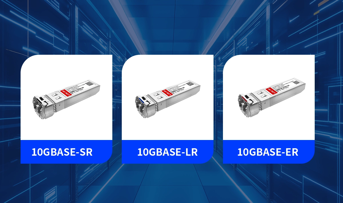
For example, selecting between 10GBASE-SR, 10GBASE-LR, and 10GBASE-ER is essentially choosing different PMDs optimized for 300m, 10km, or 40km.
➡️ Example PMD Summary Table
Replace values with the exact parameters from the chosen SFP+ module datasheet.
PMD Attribute | Typical Value | Description |
|---|---|---|
Wavelength | 1310nm | Single-mode, long-reach laser |
Tx Power (Min/Max) | –3dBm / +3dBm | Launch power range |
Rx Sensitivity | –14dBm | Minimum power for BER compliance |
Rx Overload | +1dBm | Maximum safe input |
Reach | 10km | Depends on fiber loss and splices |
Extinction Ratio | ≥ 3.5dB | Laser modulation quality |
➡️ PMD Testing and Compliance
A well-defined PMD test ensures reliable interoperability.
Key measurements include:
Optical power at transmitter and receiver
Eye-mask compliance
Jitter and noise margin
Testing at defined temperature points
Verification of receiver sensitivity under stressed conditions
These measurements align with IEEE compliance procedures.
➡️ Troubleshooting PMD-Related Failures
Low received power
Check connector cleanliness, unexpected fiber loss, or excessive patching.
Link flaps on long spans
Inspect Tx power aging or marginal sensitivity—optical budget may be too tight.
Multimode reaches the shorter than expected
Verify OM3/OM4 compatibility; bandwidth limitations are medium-specific.
➡️ Conclusion
The Physical Medium Dependent (PMD) sublayer is one of the foundational concepts behind Ethernet physical-layer interoperability. By specifying optical wavelength, power ranges, sensitivity, reach, and test points, PMD ensures that transceivers from different vendors operate predictably on the same fiber infrastructure.
For organizations deploying or upgrading networks, understanding PMD is critical to selecting the right optical modules and designing a link that is reliable, standards-compliant, and future-proof.
LINK-PP’s optical transceivers include clearly defined PMD specifications, making them excellent choices for robust, standards-aligned network designs.


