


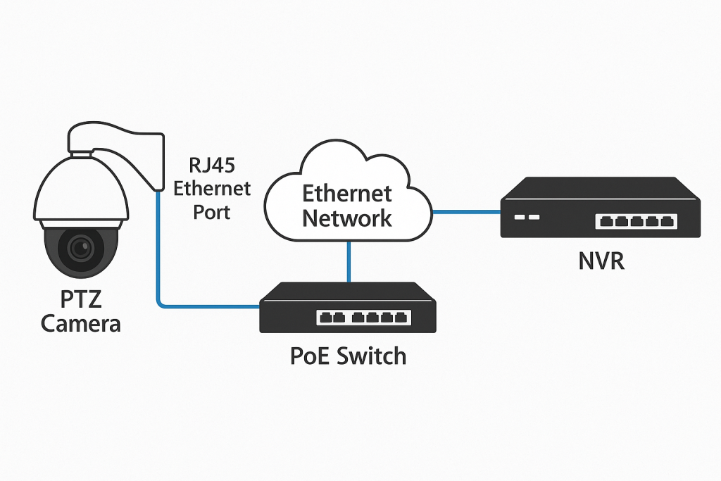
PTZ (Pan‑Tilt‑Zoom) IP cameras rely on Ethernet not just for video and control, but also for power via PoE. The small RJ45 port—often an integrated‑magnetics “MagJack”—is the electrical and mechanical gateway that keeps that entire link stable. Its internal transformers, shielding, pin plating, and even how it bonds to chassis ground directly influence power headroom, EMI/ESD immunity, surge robustness, and outdoor durability. In other words, getting the RJ45 connector right is foundational to PTZ reliability.
➡️ What an RJ45 with integrated magnetics actually does
At a glance, “RJ45” typically refers to the 8P8C modular connector used for Ethernet. In PTZ cameras and NVRs, it is commonly a MagJack: a shielded connector that integrates isolation transformers and common‑mode chokes. The magnetics provide galvanic isolation (typically around 1500Vrms, often specified as 2250V DC for 60 seconds in datasheets), keep differential signaling clean at Gigabit and multi‑gigabit speeds, and route PoE DC through transformer center taps while data rides on the pairs. This integration reduces PCB complexity and can improve EMC.
Just as important: a bare PCB jack is not weather‑sealed. True IP66/67 weather protection comes from the enclosure design and sealed accessories (for instance, push‑pull RJ45 feed‑throughs on outdoor domes), not from the RJ45 jack alone—as shown in the AXIS P5655‑E datasheet (2021).
According to the Ethernet Alliance 2019 PoE overview, typical available power at the powered device (PD) is 12.95W (Type 1), 25.5W (Type 2), up to 51W (Type 3), and up to 71.3W (Type 4). These values already account for cable loss rules in the standard; real installations still benefit from margin.
➡️ PoE classes and power budgeting for PTZ
PTZ cameras are dynamic loads: motors for pan/tilt/zoom, heaters for cold climates, and IR illuminators can all cause current peaks. Choosing the right PoE class and designing headroom avoids brownouts, resets, or visible artifacts like dropped frames.
IEEE 802.3af (Type 1): PSE nameplate 15.4 W; PD up to about 12.95 W.
IEEE 802.3at (Type 2, PoE+): PSE 30 W; PD up to 25.5 W.
IEEE 802.3bt (4‑pair PoE):
Type 3: PSE up to 60 W; PD up to ~51 W.
Type 4: PSE 90–100 W; PD up to ~71.3 W.
These PD numbers and class behaviors are summarized in the Ethernet Alliance 2019 PoE overview. When scoping PTZs with heaters or long cable runs, aim for a class above steady‑state needs to absorb surges and cable losses.
Recommended practice: treat the connector’s center‑tap current path and thermal environment as part of the power budget. Ensure the MagJack is rated for the expected PoE++ current and ambient, not just the nominal data rate.
➡️ Surge, ESD, and grounding: the EMC reliability stack
Outdoor cabling can pick up static discharges and induced surges. A robust RJ45 implementation is a system: connector, magnetics, PCB protection, and enclosure bonding all work together.
ESD immunity (IEC 61000‑4‑2): Level 4 calls for ±8 kV contact and ±15 kV air.
Surge immunity (IEC 61000‑4‑5): Industrial/outdoor links can see 1–2kV differential and 2–4kV common‑mode surges, depending on installation and protection choices.
Design practices for Ethernet ports in industrial environments:
Place low‑capacitance TVS arrays on the PHY side of the magnetics with very short leads to minimize inductance and protect the PHY from fast transients that couple through the transformer, per Texas Instruments’ application note on protecting Ethernet ports from surge (2019).
Choose TVS devices whose IEC 61000‑4‑2 ESD rating and 8/20 µs surge current match your environment. The engineering article on designing TVS for Gigabit Ethernet (2023) summarizes low‑cap device selection and placement trade‑offs.
Bond the RJ45 shield to chassis/earth to provide a 360‑degree return path for RF and surge currents, reducing noise injection into signal ground, as advised in the ODVA EtherNet/IP Media Planning and Installation Manual (2020).
➡️ Outdoor mechanics: sealing, temperature, and plating
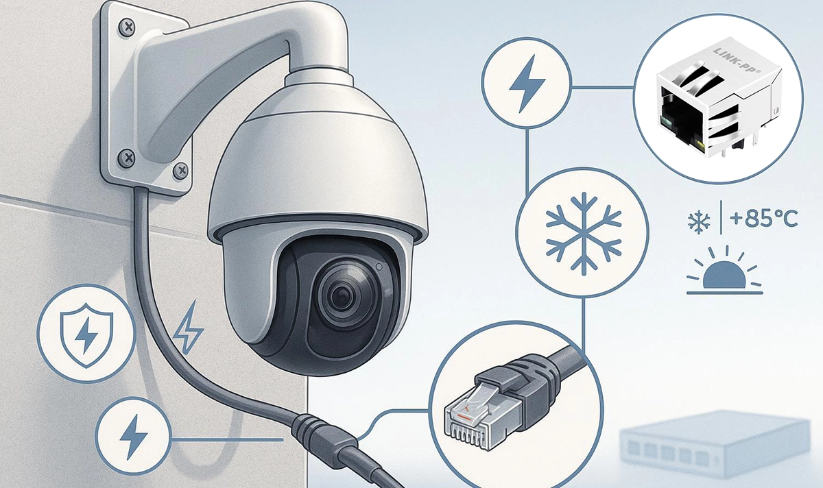
A PTZ camera’s Ethernet port must coexist with rain, dust, temperature swings, and vibration:
Sealing is achieved at the enclosure interface, not by the PCB jack alone. Many outdoor PTZs specify a push‑pull RJ45 connector accessory or sealed gland to maintain IP66/67 while allowing service—the AXIS P5655‑E datasheet (2021) exemplifies enclosure‑level IP and operating temperature ranges when installed as directed.
Temperature: For harsh climates, align the connector’s and protection devices’ operating range with the camera’s spec (e.g., −40 to +85 °C components for industrial designs).
Plating and durability: Gold plating thickness on contacts (e.g., 30–50 µin) resists fretting corrosion and maintains low contact resistance under vibration and humidity.
Shielded shells and strain relief: Use a metal‑shielded jack and ensure the mating solution provides strain relief to the enclosure.
➡️ PHY/SoC compatibility and layout
For a stable link at 1G/2.5G/5G:
Follow the PHY vendor’s reference design for magnetics selection and the Bob‑Smith termination network.
Maintain 100Ω differential impedance, minimize PHY‑to‑connector trace length, and match pair lengths tightly.
Validate insertion/return loss and mode conversion, and run pre‑compliance EMC checks early.
➡️ Engineering checklist (for design reviews)
PoE power class and margin
Confirm IEEE 802.3 af/at/bt type and PD budget; add headroom for motor/heater/IR peaks.
Verify MagJack center‑tap current and thermal limits at the expected ambient.
Isolation and signal integrity
Datasheet isolation rating ≥1500 Vrms (commonly 2250 VDC/60 s).
Return/insertion loss and CMR suitable for 1G+ links.
ESD/surge protection
TVS arrays with low capacitance on the PHY side of magnetics; track length minimized.
Target IEC 61000‑4‑2 Level 4 ESD and appropriate 61000‑4‑5 surge ratings for your site class.
Shielding and bonding
Shielded metal shell; defined shield‑to‑chassis bond path.
Enclosure provides 360° shield continuity.
Environment
Component operating range consistent with camera spec (e.g., −40 to +85 °C).
Adequate contact plating thickness and mechanical retention.
PHY alignment
Magnetics compatible with PHY reference design; correct Bob‑Smith values.
Clean 100 Ω differential routing and pair matching.
➡️ Procurement checklist (for buyers and program managers)
Standards and ratings
Stated IEEE PoE support (af/at/bt) and current ratings with conditions (ambient, ΔT).
Isolation and EMC claims with explicit values and test methods (e.g., 2250 VDC/60 s, IEC 61000‑4‑2/‑4‑5).
Environmental readiness
Operating temperature rating, shielding, plating thickness, and any compliance statements.
Clear statement that IP sealing depends on enclosure/accessories.
Lifecycle and availability
Supply continuity, alternates with footprint compatibility, inventory visibility, lead time guarantees.
Documentation and support
Pinouts, reference footprints, 3D models, and sample availability for early validation.
➡️ Bringing it all together
A reliable PTZ camera link is more than a cable and a port. It’s an engineered interface where the RJ45’s integrated magnetics, shield bonding, PoE current path, and mechanical integration work together to deliver clean data and stable power—through ESD strikes, motor surges, and weather. Anchor your choices in the IEEE PoE power classes, verify isolation and EMC at the connector and PCB, and treat outdoor sealing as an enclosure/accessory attribute.
If you’re validating a PTZ design or refreshing a bill of materials, we can help you compare PoE classes, isolation specs, and EMC options one‑to‑one against your requirements. Contact LINK‑PP to request samples or a quick spec review for your RJ45/MagJack shortlist.


