🌐 What is a Network Filter (LAN Filter)?
A Network Filter (often called a LAN filter or Ethernet filter) is an assembly of passive components—most commonly common-mode chokes (CMCs), isolation transformers, and sometimes discrete capacitors or resistive terminations—designed to attenuate unwanted electromagnetic interference (EMI) while allowing the desired differential Ethernet signals to pass with minimal distortion. Network filters reduce radiated emissions, improve immunity to external noise, and protect PHY circuitry from cable-borne transients.
Key components inside a LAN filter
Common-mode choke (CMC): Presents high impedance to noise that is common to both conductors of a differential pair while leaving the differential signal largely unaffected.
Isolation transformer: Provides galvanic isolation (often rated to meet IEEE 802.3 port isolation levels) and helps with matching differential pair impedance.
Termination / TVS / capacitors (supporting parts): Used for ESD/surge protection and to provide recommended terminations like the Bob Smith network in PoE applications.
🌐 Why network filters matter: EMI, isolation, and signal integrity
Network filters are applied for three main reasons:
EMI suppression (emissions & immunity): CMCs reduce common-mode currents that would otherwise radiate or be induced by nearby sources. This helps products pass EMC/EMI testing and reduces interference with radio receivers and sensitive electronics.
Isolation & safety: Ethernet isolation transformers provide the galvanic barrier required by standards; many designs call for at least 1500 Vrms isolation between line and system to protect users and equipment.
Protecting PHY chips and PoE operation: Filters and recommended TVS/termination schemes limit surge and ESD exposure and support stable PoE operation by controlling common-mode behavior on powered pairs.
🌐 How common-mode chokes work in Ethernet magnetics
A well-designed CMC is wound so that differential currents cancel magnetically while common-mode currents add — the result is low impedance for the intended differential data and high impedance for the unwanted common-mode noise. In many Ethernet modules, the CMC is integrated with the transformer or supplied as a matched discrete component to preserve CMRR (common-mode rejection ratio) across the relevant frequency band. Designers choose trifilar/quad-filar windings and cores sized to avoid saturation under PoE currents.
🌐 Typical use cases: where you’ll find network filters
Consumer and audiophile gear: Inline Ethernet filters are marketed to reduce RF/EMI pickup in audio-over-IP setups. While they don’t change the digital payload, they can reduce audible artifacts from RFI-induced noise in downstream audio equipment.
Industrial Ethernet & automation: Harsh EMI environments and long cable runs benefit from robust magnetics (transformer + CMC) and surge/ESD protection.
Telecom & datacom equipment: Switches, routers, and PHY modules require magnetics that meet IEEE isolation and EMC performance targets.
🌐 Selecting a network filter: practical checklist
Use this checklist when evaluating LAN filters/magnetics for a design:
Ethernet standard & data rate compatibility: Ensure components support your link rate (10/100/1000/2.5G/10G as appropriate). Integrated magnetics are specified per standard.
Isolation rating: Verify transformer isolation (commonly ≥1500 Vrms for IEEE-802.3).
CMRR / insertion loss: Look at CMRR across frequency and insertion loss at your operating bandwidth to avoid signal degradation.
PoE current handling & saturation margin: If using PoE, confirm choke/core selection supports the required DC bias without saturating.
Package & thermal/board constraints: Chip-style vs. discrete modules—consider PCB footprint, mounting (SMD vs through-hole), and thermal derating.
Regulatory and EMC test history: Prefer parts or modules with published EMC test results or vendor application notes.
🌐 Quick design notes
Put magnetics (transformer + CMC) as close to the RJ45 port / cable entry as practical, to minimize board-level loop areas.
Use low-capacitance TVS diodes if vendor application notes recommend them; large capacitances can disturb high-speed eye diagrams.
Test the final PCB in situ for EMC and common-mode emissions — simulation helps, but real-world cable runs and chassis coupling often reveal issues.
🌐 How LINK-PP Products Fit
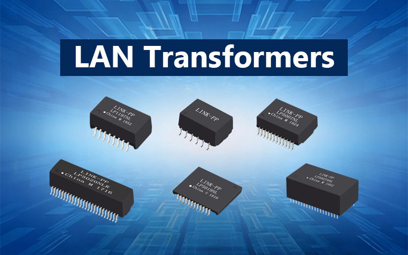
LINK-PP provides a wide portfolio of Integrated RJ45 connectors and LAN transformers designed for Ethernet and PoE applications. Each product is accompanied by a detailed Product Drawing, which clearly specifies supported data rates, isolation voltage, and PoE current rating.

🌐 Summary
A Network Filter combines CMCs, transformers and protection parts to reduce EMI, preserve signal integrity, and meet isolation/safety standards for Ethernet ports.
Choose filters that match your data rate, PoE needs, and EMI goals; prioritize tested modules with clear isolation and CMRR specs.
🌐 Further reading
For deeper technical guidance on Ethernet magnetics, filters, and EMC/EMI design, explore LINK-PP’s resources:


