


As data center networks transition from 100G to 400G architectures, engineers are increasingly faced with a practical selection question: QSFP28 vs. QSFP-DD — which transceiver form factor is the right choice?
While both QSFP28 and QSFP-DD belong to the QSFP family, they target fundamentally different generations of bandwidth density, electrical signaling, and switch platform design. QSFP28 has long been the workhorse for 100G Ethernet deployments, offering mature ecosystems, predictable power envelopes, and wide interoperability. QSFP-DD, by contrast, is designed to unlock 400G — and even 800G — without increasing front-panel port density, at the cost of higher power, tighter signal integrity margins, and stricter thermal requirements.
From a system perspective, this is not merely a speed upgrade. Moving from QSFP28 to QSFP-DD impacts electrical lane architecture, modulation schemes (NRZ vs. PAM4), fiber breakout strategies, and even data center cooling design. Choosing the wrong module can lead to interoperability issues, unstable links, or unnecessary infrastructure upgrades.
This guide provides a clear, engineer-focused comparison of QSFP28 and QSFP-DD, covering electrical design, supported data rates, power consumption, compatibility considerations, and real-world deployment scenarios. By the end, you will be able to confidently select the right 100G or 400G transceiver module based on your network architecture, switch platform, and long-term scalability goals.
1️⃣ What Is QSFP28 and What Is QSFP-DD? (Quick Definition)
QSFP28 and QSFP-DD are QSFP-family pluggable transceiver form factors designed for different Ethernet generations. QSFP28 is optimized for stable 100G deployments using four electrical lanes, while QSFP-DD doubles the electrical interface to support 400G and beyond without increasing front-panel port density. The key distinction lies in lane count, modulation method, and power envelope, which directly affects switch design, cooling strategy, and scalability planning.
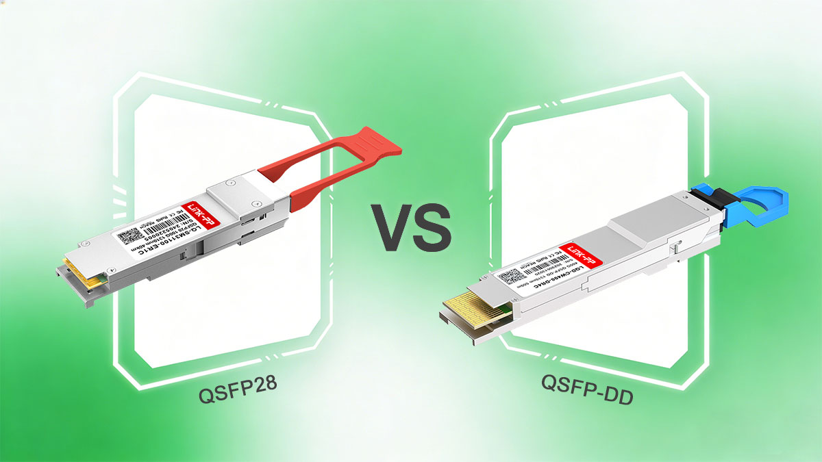
QSFP28 Overview (100G Form Factor)
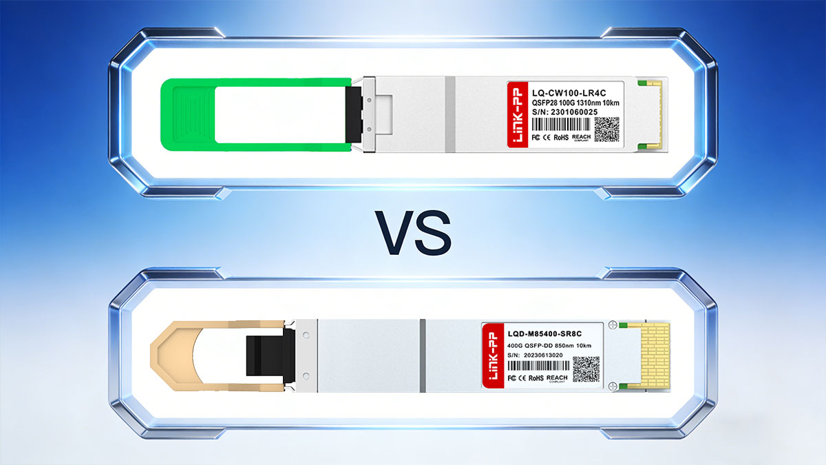
QSFP28 Module supports 100G Ethernet using 4 × 25G NRZ electrical lanes. It is widely deployed in data center leaf and spine switches, aggregation layers, and enterprise core networks. Typical use cases include 100GBASE-SR4, DR, and LR optics.
Typical power consumption: ~3.5–4.5 W per module, enabling high port density with predictable thermal behavior.
QSFP-DD Overview (400G Form Factor)
QSFP-DD Module supports 400G Ethernet using 8 × 50G PAM4 electrical lanes, effectively doubling lane density within a QSFP-sized module. “Double Density” refers to the additional row of electrical contacts, allowing higher bandwidth without expanding panel width. QSFP-DD is primarily used in hyperscale data centers and AI fabrics.
Typical power consumption: ~10–14 W for 400G modules.
2️⃣ Key Differences Between QSFP28 and QSFP-DD
Understanding the technical differences between QSFP28 and QSFP-DD is critical for engineers selecting the right 100G transceiver or 400G transceiver. The choice affects bandwidth, power, thermal design, port density, and backward compatibility. Below is a structured comparison highlighting the core trade-offs and deployment implications.
Feature / Parameter | QSFP28 (100G) | QSFP-DD (400G) |
|---|---|---|
Electrical Lanes | 4 × 25G NRZ | 8 × 50G PAM4 |
Aggregate Bandwidth | 100G | 400G |
Modulation | NRZ | PAM4 (dominant), NRZ (legacy) |
Typical Power Consumption | 3.5–4.5 W | 10–14 W |
Thermal Considerations | Moderate | High |
Port Density / Front-Panel Efficiency | Standard | Doubled per port |
Backward Compatibility | N/A | Mechanical with QSFP28/QSFP+ |
Deployment Target | Enterprise, moderate-density DC | Hyperscale, AI/HPC, high-radix leaf/spine |
Connector / Cage | QSFP-DD cage (dual-row contacts) | |
Breakout Support | Limited | 400G → 4 × 100G (platform-dependent) |
● Bandwidth and Electrical Lane Architecture
QSFP28 provides 100G per port using 4 × 25G NRZ lanes, while QSFP-DD doubles the electrical interface to 8 × 50G PAM4 lanes for 400G. The additional lanes in QSFP-DD align better with next-generation ASIC SerDes fabrics, reducing breakout complexity. NRZ vs PAM4 modulation affects signal integrity and requires stronger on-module DSP and FEC. Engineers must consider lane mapping, host PCB routing, and channel design when migrating from QSFP28 to QSFP-DD to maintain link stability and performance.
● Power Consumption and Thermal Impact
Typical QSFP28 modules draw ~3.5–4.5 W, whereas 400G QSFP-DD modules consume ~10–14 W per port. This tripling of power has direct chassis-level implications: airflow direction, fan staging, and thermal headroom become critical. High-density deployment without adequate cooling can lead to thermal throttling or reduced reliability. Engineers must plan for worst-case sustained load and integrate DOM/DDM telemetry for proactive monitoring to prevent overheating.
● Port Density and Front-Panel Efficiency
QSFP-DD delivers 400G in the same QSFP-sized footprint, doubling per-port bandwidth without expanding front-panel width. For spine or high-radix leaf switches, this increases bisection bandwidth and fabric capacity while reducing the total number of chassis needed. 100G QSFP28 remains optimal for moderate-density platforms where power and cooling budgets are constrained, but QSFP-DD enables more aggressive scaling in hyperscale and AI/HPC environments.
● Backward Compatibility and Mechanical Fit
QSFP-DD cages mechanically accept QSFP28 and QSFP+ modules, but functional compatibility is conditional. QSFP28 modules operate at their native 100G speed and rely on host firmware for proper lane mapping. QSFP-DD requires platform support for 8-lane operation and breakout logic. Mixing QSFP28 and QSFP-DD in the same chassis demands careful verification of firmware, ASIC support, and thermal planning to avoid interoperability issues.
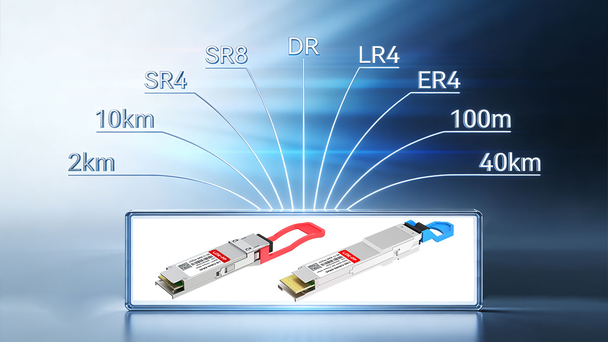
3️⃣ Optical Module Types and Reach Comparison
When selecting QSFP28 or QSFP-DD modules, understanding optical standards, reach, and fiber infrastructure is critical. Engineers and procurement teams frequently ask: “How far can this module transmit?” and “Can we reuse existing fiber?” This section summarizes common optics for both form factors and key fiber considerations.
Common QSFP28 Transceivers (100G)
QSFP28 Module Type | Fiber Type | Typical Reach | Connector | Typical Use Case |
|---|---|---|---|---|
Multimode Fiber (OM3/OM4/OM5) | ~70–100 m | MPO/MTP | Short‑reach spine/leaf links inside racks or adjacent racks | |
100GBASE-SR2 | Multimode Fiber (OM3/OM4) | ~100 m | LC (via breakouts) | Short‑reach links over parallel fiber with LC breakouts |
100GBASE-CR4 | Copper Twinax | ~5–7 m | Direct attach twinax | Very short reach, server top‑of‑rack interconnect |
Single‑mode Fiber (SMF) | ~500 m | LC or MPO | Inter‑rack, data hall aggregation | |
100GBASE-FR1 | Single‑mode Fiber | ~2 km | LC | Campus / metro‑adjacent links |
Single‑mode Fiber | ~10 km | LC (duplex / WDM) | Long‑haul metro or edge aggregation | |
Single‑mode Fiber | ~40 km | LC (WDM) | Regional or long‑distance links (high budget) |
Engineering note: SR4 is cost-effective for existing MMF; DR/LR4 options require SMF with proper Tx/Rx power planning.
Common QSFP-DD Transceivers (400G)
Module Type | Fiber Type | Typical Reach | Connector | Lane Count / Aggregation | Use Case |
|---|---|---|---|---|---|
400GBASE-SR8 | Multimode (OM4/OM5) | ~100 m | MPO/MTP | 8 × 50G | Short-reach leaf/spine links |
400GBASE-DR4 | Single-mode | ~500 m | MPO or LC | 4 × 100G / 8 × 50G | Inter-rack / campus |
Single-mode | ~2 km | LC | 4 × sub-aggregates | Metro-adjacent links | |
Single-mode | ~10 km | LC (duplex/WDM) | 4 λ WDM | Metro / edge aggregation |
Engineering tip: Always verify Tx/Rx optical budgets, FEC requirements, and vendor-specific variations.
Fiber Infrastructure Considerations
MMF vs. SMF reuse: SR/SR8 can often reuse existing multimode fiber; DR/FR/LR may reuse single-mode fiber, but verify link budgets.
Connector type changes: SR4/SR8 typically use MPO; LR/FR modules often use LC duplex, requiring patching or adapter planning.
Migration planning tips: Standardize fiber types and connectors per layer, plan for optical reach and FEC, and integrate telemetry to monitor optical power and temperature during upgrades.
4️⃣ When QSFP28 100G Is the Right Choice
Not every deployment needs to upgrade to QSFP-DD. Choosing QSFP28 over QSFP-DD can save cost, reduce power/thermal risk, and simplify operations—especially in networks where 400G isn’t required today. This section helps engineers and procurement teams decide when sticking with 100G optics is the most pragmatic path.
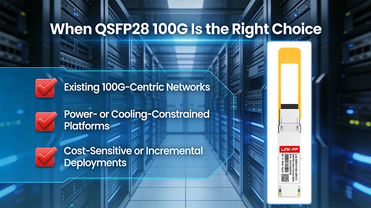
Existing 100G-Centric Networks
Networks fully built on 100G leaf/spine fabrics may not require 400G ports.
QSFP28 modules maintain existing cabling, breakout configurations, and firmware without major changes.
Ideal for enterprise or SMB environments where east-west bandwidth demands remain moderate.
Practical takeaway: Avoid unnecessary complexity and cost if your network’s growth requirements are already met by 100G.
Power- or Cooling-Constrained Platforms
QSFP-DD 400G modules draw ~10–14 W per port; QSFP28 only ~3.5–4.5 W.
Dense QSFP-DD deployments can overwhelm existing fan curves or chassis thermal limits.
Legacy switches or rack designs with tight airflow budgets may be unable to handle 400G heat density safely.
Practical takeaway: Stick with QSFP28 when the chassis or data center cannot support higher per-port power and thermal load without costly upgrades.
Cost-Sensitive or Incremental Deployments
QSFP-DD modules, optics, and compatible switches typically cost more than QSFP28.
For incremental growth or temporary bandwidth upgrades, QSFP28 can meet operational needs at lower CAPEX.
Avoid over-investment in 400G-capable optics if your expansion horizon is short or uncertain.
Practical takeaway: QSFP28 is often the best choice when budget constraints outweigh the need for maximum per-port bandwidth.
5️⃣ When QSFP-DD Module Is the Better Option
QSFP-DD becomes the preferred choice when network performance, port density, and future-proofing outweigh cost and power considerations. Engineers and procurement teams should consider QSFP-DD 400G when scaling beyond 100G fabrics, planning for hyperscale workloads, or preparing for 800G evolution.

High-Density Spine and Leaf Switches
Hyperscale data centers increasingly deploy QSFP-DD 400G ports in spine/leaf switches to maximize bisection bandwidth without increasing chassis width.
Doubling electrical lanes (8 × 50G) allows more bandwidth per port while preserving front-panel port count.
Supports breakout options (e.g., 400G → 4 × 100G) for flexible interconnects.
Practical takeaway: QSFP-DD is essential when port density and fabric radix are critical, enabling fewer switches to carry the same aggregate throughput.
AI / HPC Clusters with Heavy East–West Traffic
AI training and HPC clusters generate extremely high east-west traffic, often exceeding 400G per rack.
QSFP-DD enables high-bandwidth, low-latency fabrics across GPU/accelerator pods.
Short-reach SR8 or DR4 optics maximize rack-level throughput while minimizing fiber count.
Practical takeaway: QSFP-DD ensures cluster interconnects can sustain heavy east-west traffic without bottlenecks.
Preparing for 800G and Future Scaling
QSFP-DD electrical architecture (8 lanes) is already compatible with emerging 800G modules (8 × 100G PAM4).
Investing in QSFP-DD today provides a forward path for bandwidth upgrades without mechanical redesign.
Ensures new deployments are not limited by front-panel port density or ASIC lane mapping in the near future.
Practical takeaway: QSFP-DD is the safe choice for organizations planning to scale to 800G and beyond while maintaining standard form factor continuity.
6️⃣ 100G & 400G Module Power, Cooling, and Platform Readiness Checklist
Before deploying QSFP28 or QSFP-DD modules, engineers must evaluate power, cooling, and platform readiness to ensure reliable operation. High-speed optics increase per-port power and thermal demands, and overlooking these factors can lead to throttling, link errors, or equipment failure.
1. Per-Port and Chassis Power Budget
QSFP28 (100G): Typical per-port power: 3.5–4.5 W
QSFP-DD (400G): Typical per-port power: 10–14 W; early 800G modules: 16–20 W
Checklist for engineers:
Verify per-port power vs. worst-case manufacturer spec
Calculate total chassis power with full port population
Include transient spikes (boot, traffic bursts) in budget
Ensure PSU headroom and redundant power capability
Tip: Always design for worst-case power, not typical, to avoid thermal throttling or fan overrun.
2. Airflow Direction and Thermal Validation
High-density QSFP-DD ports increase thermal load; airflow direction (front-to-back or back-to-front) critically impacts module cooling.
Key validation steps:
Map thermal zones per port and identify potential hot spots
Run stress tests under fully populated, sustained 400G traffic
Adjust fan curves, speed, or chassis venting as needed
Avoid clustering high-power modules adjacent to each other
Practical insight: Proper airflow planning ensures stable operation in hyperscale spine/leaf or AI/HPC racks.
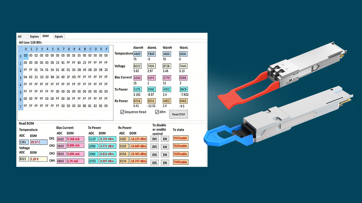
3. DOM/DDM Monitoring Requirements
Digital Optical Monitoring (DOM) or Digital Diagnostics Monitoring (DDM) is mandatory, not optional.
Minimum monitored parameters:
Module temperature
Supply voltage
Tx/Rx optical power
Laser bias current
Recommended practice:
Integrate DOM/DDM telemetry into network management systems (NMS)
Set proactive alarms for threshold violations
Use trending to predict fiber degradation or cooling inefficiency before link failure
Takeaway: Continuous monitoring reduces operational risk and ensures the network meets SLAs under full 400G deployment.
7️⃣ QSFP28 vs. QSFP-DD: Cost and Operational Considerations
Selecting between QSFP28 and QSFP-DD is not only about speed—it directly impacts CAPEX, OPEX, cabling, and operational complexity. Engineers and procurement teams must evaluate cost per port, infrastructure changes, and long-term management effort to make the right decision.
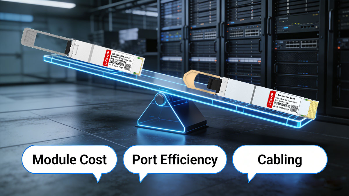
Module Cost vs Port Efficiency
QSFP28 (100G): Lower per-module cost, widely available, mature supply chain.
QSFP-DD (400G): Higher per-module cost but delivers 4× bandwidth in the same panel footprint.
Evaluation guidance:
Compare cost per effective bandwidth per rack unit instead of per-module cost
Consider reduced chassis count and switch consolidation with QSFP-DD
Factor in energy cost: higher per-port power of QSFP-DD can offset CAPEX savings if thermal design is inadequate
Takeaway: QSFP-DD may have higher upfront cost but can reduce total infrastructure spend through higher port efficiency and fewer devices.
Cabling and Infrastructure Changes
QSFP28: Uses 100G optics (SR4/DR/LR4), compatible with existing MMF/SMF and LC/MPO connectors in many deployments.
QSFP-DD: 400G optics (SR8/DR4/FR4/LR4) may require:
MPO cabling for SR8
Additional fiber count or re-termination for higher lane aggregation
Validation of patching, polarity, and breakout configurations
Migration tip: Evaluate whether existing fiber plant and patch panels support 400G without major rework.
Takeaway: QSFP-DD deployments may involve moderate to significant cabling adjustments—plan in advance to avoid operational disruption.
Long-Term Operational Complexity
QSFP28: Easier to maintain, fewer thermal challenges, lower monitoring overhead.
QSFP-DD: Requires careful management of:
DOM/DDM telemetry for temperature, optical power, and voltage
Higher power and airflow planning in chassis
Breakout and lane-mapping logic for interoperability
Recommendation: Standardize module SKUs and optics across deployments to reduce troubleshooting and operational overhead.
Scaling insight: QSFP-DD allows migration to 800G with minimal front-panel redesign but requires disciplined operational practices.
Takeaway: QSFP-DD offers future-proof scalability at the cost of more complex operational management; proper planning mitigates risk and maximizes return on investment.
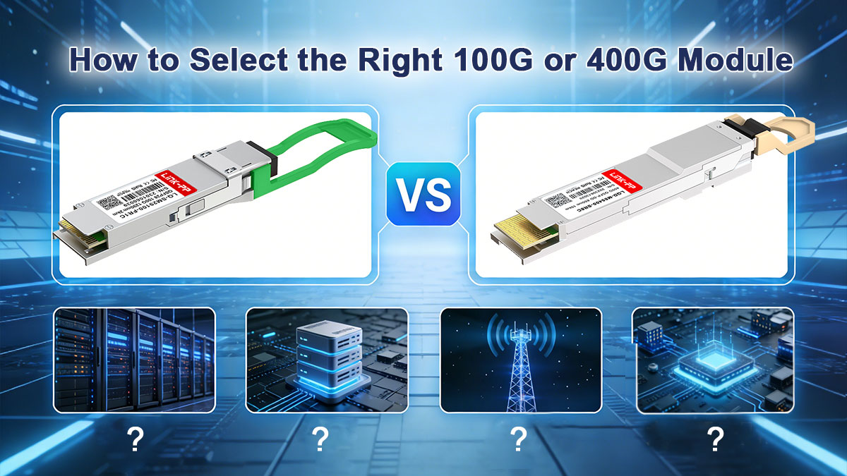
8️⃣ How to Select the Right 100G or 400G Module (Decision Guide)
Selecting between QSFP28 100G and QSFP-DD 400G modules is not just a matter of speed—it requires a system-level evaluation of power, thermal design, optical infrastructure, and forward compatibility. This guide provides a practical framework for engineers and procurement teams to make informed deployment decisions.
QSFP28 vs. QSFP-DD — Side-by-Side Comparison Table
Feature / Parameter | QSFP28 (100G) | QSFP-DD (400G) | Notes / Engineering Implications |
|---|---|---|---|
Electrical Lanes | 4 × 25G NRZ | 8 × 50G PAM4 | QSFP-DD doubles lane density for higher per-port bandwidth |
Aggregate Bandwidth | 100G | 400G (typical), 800G (early/experimental) | QSFP-DD enables 4× bandwidth without increasing front-panel width |
Modulation | NRZ | PAM4 | PAM4 doubles bits per symbol but requires stronger DSP & FEC |
Typical Module Power | 3.5–4.5 W | 10–14 W (400G), 16–20 W (800G early) | Higher power impacts chassis thermal planning |
Port Density Impact | Baseline | Same panel width, 4× capacity | Ideal for spine/leaf switches needing more bandwidth per RU |
Backward Compatibility | N/A | Mechanical: QSFP+/QSFP28; Functional: conditional | Requires host ASIC & firmware support for older modules |
Typical Use Cases | 100G leaf/spine, aggregation | 400G spine/leaf, AI/HPC clusters, core aggregation | QSFP-DD targets hyperscale & high-bandwidth deployments |
Optical Modules / Reach | 100GBASE-SR4 / DR / LR4 (~100 m–10 km) | 400GBASE-SR8 / DR4 / FR4 / LR4 (~100 m–10 km) | Fiber type & connector changes may be needed |
Chassis Thermal Considerations | Standard cooling | Critical: airflow, fan curves, hotspot mitigation | QSFP-DD requires careful thermal planning and monitoring |
DOM/DDM Monitoring | Optional | Mandatory for stable ops | QSFP-DD modules expose detailed telemetry for temperature, voltage, and optical power |
Migration Path | 100G only | 400G → 800G | QSFP-DD enables future-proof scaling without front-panel redesign |
Questions Should Ask Before Choosing
Current and Future Bandwidth Requirements
Is your existing network limited to 100G, or do you need 400G per port for spine/leaf upgrades?
Will your network scale toward 800G in the future?
Host ASIC and Firmware Support
Does your switch or board support 8-lane electrical interfaces for QSFP-DD?
Are breakout modes (e.g., 400G → 4 × 100G) supported and validated?
Power and Thermal Constraints
Can your chassis sustain 10–14 W per QSFP-DD port under full load?
Are airflow, fan curves, and hot-spot mitigation validated for dense deployments?
Optical Infrastructure and Reach
Is multimode (MMF) or single-mode fiber (SMF) available?
Are MPO-to-LC changes required for 400G optics (SR8, DR4, FR4, LR4)?
Have link budgets been calculated, including Tx/Rx power, fiber loss, and contingency margin?
Backward Compatibility and Mixed Deployments
Will QSFP-DD coexist with QSFP28 modules in the same chassis?
Are DOM/DDM monitoring and firmware lane mapping compatible with both module types?
Typical Selection Scenarios
① Stay at 100G
Networks designed around 100G performance with limited growth expectations
Platforms with constrained power or cooling capacity
Cost-sensitive or incremental deployment requirements
Recommended modules: 100G QSFP28, minimal changes to existing infrastructure
② Migrate to 400G
High-density spine or leaf switches requiring higher per-port bandwidth
AI/HPC clusters or hyperscale data centers with heavy east–west traffic
Systems capable of handling QSFP-DD thermal and power demands
Recommended modules: 400G QSFP-DD (SR8, DR4, FR4, LR4 depending on reach)
③ Mixed Deployment
Gradual network upgrade with partial 400G rollout
Requires careful verification of host ASIC, firmware, and DOM telemetry support
Thermal planning and airflow validation are critical
Recommended strategy: QSFP28 + QSFP-DD mix, with pre-production lab testing for interoperability
9️⃣ QSFP28 vs. QSFP-DD FAQs
Q1: Is QSFP-DD backward compatible with QSFP28?
QSFP-DD is mechanically compatible with QSFP28 cages, but functional interoperability depends on host ASIC, PCB routing, and firmware support. QSFP28 modules will run at their native 100G speed when inserted into a QSFP-DD cage; they cannot operate at 400G. Breakout modes and lane mapping must also be verified.
Q2: Does 400G always replace 100G?
Not necessarily. 400G QSFP-DD is optimal for high-density spine/leaf switches, AI/HPC clusters, or future-proofed data centers. Many networks continue operating 100G QSFP28 for incremental upgrades, cost-sensitive deployments, or power-constrained platforms. Selection depends on traffic requirements, power, and thermal capacity.
Q3: What is the typical power difference?
QSFP28 (100G): ~3.5–4.5 W per module
QSFP-DD (400G): ~10–14 W per module (early 800G can be 16–20 W)
Engineers must plan chassis-level power and airflow accordingly, using worst-case power values for full port population.
Q4: Can QSFP28 and QSFP-DD coexist in one switch?
Yes, mechanically they can, but functional coexistence requires verified firmware and ASIC support for lane mapping, breakout modes, and DOM telemetry. Thermal planning is critical, as QSFP-DD modules produce higher per-port heat than QSFP28.
🔟 Final Selection Guidance for QSFP28 vs. QSFP-DD
100G/400G Modules Selection Logic
When choosing between QSFP28 (100G) and QSFP-DD (400G), follow a simple logic:
QSFP28 → ideal for existing 100G networks, power- or cooling-constrained platforms, or incremental deployments.
QSFP-DD → preferred for high-density spine/leaf switches, AI/HPC clusters, or when planning future 400G–800G scaling.
Engineers should always validate host ASIC support, firmware compatibility, power budgets, and thermal headroom before committing to a deployment. Mixed deployments require careful testing to ensure functional interoperability.
Explore LINK-PP QSFP28 & QSFP-DD Solutions
For verified, data-center-grade optical modules with detailed technical documentation and proven interoperability, visit the LINK-PP Official Store:
These modules are designed to simplify deployment, support spine/leaf and AI/HPC fabrics, and provide a forward-compatible path to 400G and beyond, while ensuring reliability and long-term operational stability.


