

In modern network infrastructure, few components are as widely used—and as frequently misunderstood—as the SFP form-factor. Whether you are designing enterprise networks, upgrading data center links, or selecting optical modules for Ethernet applications, understanding this concept is essential for making the right hardware decisions.
At its core, the SFP (Small Form-Factor Pluggable) standard defines the physical design and interface of pluggable transceivers. However, many users mistakenly associate it with speed, distance, or even protocol support. This confusion often leads to common deployment issues such as incompatible modules, failed links, or unnecessary hardware costs.
The reality is that the SFP form-factor is only one piece of a much larger compatibility puzzle. Factors like data rate (SFP vs. SFP+), fiber type (single-mode vs. multimode), wavelength, and vendor compatibility all play critical roles in determining whether a module will function correctly in a given system.
This guide is designed to provide a clear, engineer-level explanation of the SFP form-factor while aligning with real-world usage and current industry trends. Drawing on practical deployment insights and common questions from network engineers, we will break down:
What the SFP form-factor actually means
How it differs from SFP+, SFP28, and other transceiver standards
The most important compatibility rules you must follow
Common mistakes and how to avoid them
👉 By the end of this article, you will not only understand the theory behind SFP form-factors but also gain the practical knowledge needed to select, deploy, and troubleshoot SFP modules with confidence in real network environments.
🛑 What Is the SFP Form-Factor?
The SFP form-factor (Small Form-Factor Pluggable) is a standardized physical design for compact, hot-swappable transceiver modules used in networking equipment. It defines the module’s size, mechanical interface, and electrical connection to the host device, but does not determine speed, transmission distance, or protocol.
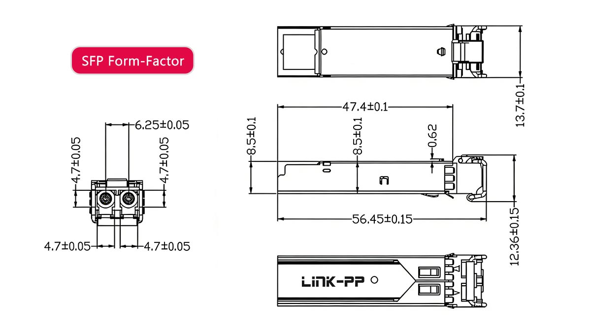
SFP Form-Factor Simple Definition
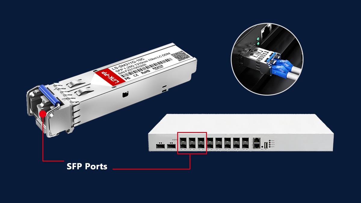
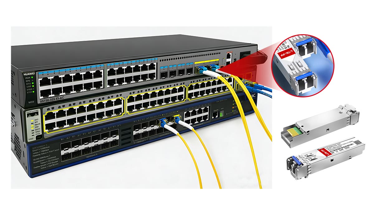
At a basic level, the SFP form-factor describes how a transceiver module is built and how it fits into a network device, such as a switch, router, or media converter.
For both beginners and experienced engineers, it helps to think of SFP as:
👉 A standardized plug-in interface that allows different types of transceivers (optical or copper) to be inserted into the same port.
Key Characteristics:
Compact size designed for high port density
Hot-swappable, allowing replacement without powering down equipment
Standardized electrical interface (defined by industry MSA specifications)
Supports both:
Optical transceivers (fiber-based)
Copper transceivers (RJ45 Ethernet)
Common Use Cases:
Gigabit Ethernet (1G) links
Fiber uplinks in enterprise switches
Telecom and access networks
What the SFP Form-Factor Does and Does Not Define
Understanding what the SFP form-factor does—and does not—define is critical for avoiding compatibility issues.
✅ What It Defines:
Physical dimensions of the module
Connector alignment with the host port
Electrical interface between module and device
Mechanical insertion/removal (plug-and-play design)
❌ What It Does NOT Define:
Data rate (e.g., 1G, 10G, 25G)
Transmission distance (e.g., 300 m, 10 km, 40 km)
Optical wavelength (e.g., 850 nm, 1310 nm, 1550 nm)
Network protocol (Ethernet, Fibre Channel, etc.)
👉 These parameters are determined by the specific module type, not the form-factor itself.
Example:
Two modules can share the same SFP form-factor but differ completely in function:
1000BASE-SX SFP → multimode fiber, short distance
1000BASE-LX SFP → single-mode fiber, longer distance
Both fit into the same port—but are not interchangeable in all scenarios.
Why This Concept Is Often Misunderstood
The SFP form-factor is frequently misunderstood due to a combination of naming conventions, marketing practices, and real-world deployment complexity.
1. Confusion Between Form-Factor and Performance
Many users assume:
“SFP = 1G”
“SFP+ = 10G”
While this is often true in practice, it is not what the form-factor defines. The physical design remains nearly identical, while performance depends on internal electronics.
2. Misleading Product Naming in the Market
Some vendors label products as:
When they actually mean:
SFP+ (10G-capable module)
👉 This leads to incorrect purchases and compatibility issues.
3. Overlapping Compatibility Across Generations
Because SFP, SFP+, and even SFP28 share similar physical designs:
Users assume full compatibility across all ports
In reality, compatibility depends on:
Host port support
Firmware validation
Electrical signaling
4. Real-World Deployment Complexity
In practical environments, multiple variables interact:
Fiber type (single-mode vs multimode)
Wavelength matching
Vendor-specific restrictions
Power and thermal limits
👉 As a result, many failures are incorrectly attributed to the “form-factor,” when the root cause lies elsewhere.
The SFP form-factor defines how a module fits—not how it performs.
🛑 What Is a Transceiver Form-Factor in Networking?
A transceiver form-factor is the standardized physical design of a pluggable module used to transmit and receive data in networking equipment. It defines the size, fiber connector type, and host interface, while performance characteristics such as speed and distance are defined by the module’s internal technology.
Physical Interface vs. Electrical Performance
One of the most important concepts in networking hardware design is the distinction between physical interface and electrical performance.
Physical Interface (Form-Factor Defines This)
The form-factor determines:
The size and shape of the module
How it fits into a port on a switch or router
The mechanical and electrical connection to the host device
The type of external connector (e.g., LC, MPO, RJ45)
👉 This ensures that modules from different vendors can physically fit into standardized ports.
Electrical Performance (Form-Factor Does NOT Define This)
Performance characteristics are independent of form-factor and include:
Data rate (1G, 10G, 25G, 100G)
Signal encoding and modulation
Transmission distance
Optical wavelength or copper signaling
👉 Two modules with the same form-factor can have completely different performance capabilities.
Practical Insight:
This separation allows network designers to:
Use the same hardware platform
Swap modules to meet different requirements
But it also introduces:
Compatibility risks if specifications are mismatched
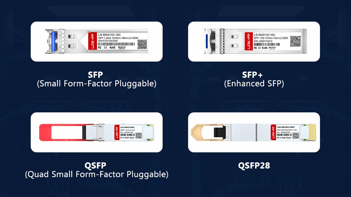
Common Transceiver Form-Factors (SFP, SFP+, QSFP, QSFP28)
Modern networks rely on several widely adopted transceiver form-factors, each designed for different bandwidth and density requirements.
SFP (Small Form-Factor Pluggable)
Typical speed: 1G
Use case: access networks, legacy systems
SFP+ (Enhanced SFP)
Typical speed: 10G
Same physical size as SFP
Widely used in enterprise and data centers
QSFP (Quad Small Form-Factor Pluggable)
Typical speed: 40G
Uses 4 parallel lanes
Higher port density than SFP
QSFP28
Typical speed: 100G
Advanced signaling for high-speed networks
Common in cloud and hyperscale data centers
Key Comparison Insight:
Form-Factor | Typical Speed | Port Density | Common Use Case |
|---|---|---|---|
SFP | 1G | High | Access / legacy |
SFP+ | 10G | High | Enterprise |
QSFP | 40G | Very high | Aggregation |
QSFP28 | 100G | Very high | Data centers |
👉 Despite different capabilities, each form-factor maintains a standardized physical interface within its category.
Why Form-Factor Matters in Network Design
Choosing the correct transceiver form-factor is a foundational decision in network architecture. It directly impacts performance, scalability, and cost.
1. Hardware Compatibility
Devices are built with specific port types:
SFP ports
SFP+ ports
QSFP ports
👉 Selecting the wrong form-factor results in immediate incompatibility.
2. Port Density and Space Efficiency
Smaller form-factors (like SFP/SFP+) allow:
More ports per switch
Higher network density
👉 Critical in:
Data centers
High-performance computing environments
3. Scalability and Upgrade Path
Choosing SFP+ over SFP enables:
Future upgrades to higher speeds
Better long-term ROI
👉 Modern design trend:
Deploy multi-rate ports (e.g., SFP+/SFP28 compatible)
4. Power Consumption and Thermal Design
Higher-speed modules (especially copper-based) consume more power
Thermal limits can affect:
Switch performance
Module lifespan
5. Cost Optimization
Optical modules vary significantly in cost
Using the correct form-factor avoids:
Over-specifying hardware
Unnecessary expenses
A transceiver form-factor defines the physical foundation of your network, while performance is built on top of it.
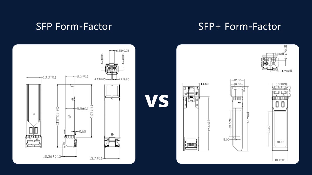
🛑 SFP vs. SFP+ Form-Factor: Key Differences Explained
SFP and SFP+ share the same physical form-factor, but differ in data rate and electrical signaling. SFP typically supports 1 Gbps, while SFP+ supports 10 Gbps, requiring higher-performance circuitry and stricter signal integrity.
Speed and Electrical Signaling Differences
The most important difference between SFP and SFP+ lies in their electrical interface and supported data rates.
Data rate: up to 1 Gbps
Signaling: Lower frequency, simpler encoding
Internal design includes more signal conditioning within the module
Data rate: up to 10 Gbps
Signaling: High-speed serial interface with tighter tolerances
Relies more on the host device for signal processing (reduced module complexity in some designs)
Key Engineering Insight:
SFP+ requires significantly better signal integrity
PCB layout, EMI shielding, and host PHY design become more critical
Not all SFP ports can handle SFP+ electrical requirements
👉 This is why speed upgrade is not just a “plug-and-play” change, even though the modules look identical.
Physical Similarities and Compatibility Myths
One of the biggest sources of confusion is that SFP and SFP+ modules are physically almost identical.
What Is the Same:
Module size and dimensions
Cage and connector interface
Insertion mechanism (hot-swappable design)
👉 Both modules fit into the same physical slot type.
Common Compatibility Myths:
❌ Myth 1: Same size means fully compatible
Reality:
Physical compatibility ≠ electrical compatibility
❌ Myth 2: Any SFP works in any SFP+ port
Reality:
Only certain SFP modules are supported, depending on the device
❌ Myth 3: “10G SFP” is just a faster SFP
Reality:
“10G SFP” is actually SFP+, not standard SFP
Practical Implication:
Because of identical size:
Users often purchase incorrect modules
Deployment failures are common in mixed environments
Real-World Compatibility Rules (What Actually Works)
Based on real deployment experience and industry best practices, the following compatibility rules apply:
✅ Rule 1: SFP Modules in SFP+ Ports
Usually supported (downward compatibility)
Works if the port supports multi-rate operation
👉 Common in enterprise switches
❌ Rule 2: SFP+ Modules in SFP Ports
Not supported
SFP ports cannot handle 10G signaling
⚠️ Rule 3: Vendor Compatibility Matters
Some devices enforce:
Vendor-locked firmware
EEPROM validation
👉 Result:
Third-party modules may:
Work normally
Show warnings
Be rejected entirely
⚠️ Rule 4: Optical Parameters Must Match
Even if form-factor and speed match:
Wavelength must match (e.g., 850 nm vs. 1310 nm)
Fiber type must match (MMF vs. SMF)
Distance rating must align
👉 Otherwise:
No link or unstable connection
⚠️ Rule 5: Copper SFP+ Modules Have Extra Constraints
Higher power consumption
Heat generation
Limited port support on some switches
Summary Table:
Scenario | Result |
|---|---|
SFP → SFP+ port | ✅ Usually works |
SFP+ → SFP port | ❌ Does not work |
Same size modules | ⚠️ Not always compatible |
Different wavelengths | ❌ Link failure |
SFP and SFP+ share a form-factor but differ fundamentally in performance and electrical design.
For reliable deployment:
Always verify port capability, module specs, and compatibility lists
Never rely on physical similarity alone
🛑 SFP Form-Factor Compatibility Guide
SFP form-factor compatibility depends on port capability, module specifications, and vendor support. While SFP and SFP+ share the same physical interface, successful operation requires matching speed, signaling, and optical parameters.
SFP in SFP+ Ports (Downward Compatibility)
One of the most common real-world scenarios is using SFP (1G) modules in SFP+ (10G) ports.
✅ When It Works:
The SFP+ port supports multi-rate operation (1G/10G)
The switch or NIC firmware allows 1G fallback
The correct module type (e.g., 1000BASE-SX or LX) is used
👉 This is widely supported in:
Enterprise switches
Data center top-of-rack (ToR) switches
⚠️ Limitations to Consider:
Not all SFP+ ports support 1G (check datasheet)
Some devices require manual port speed configuration
Performance is limited to 1 Gbps, even in a 10G port
❌ Reverse Scenario:
SFP+ modules in SFP ports do NOT work
Due to:
Higher signaling requirements
Hardware limitations of SFP ports
Practical Tip:
👉 Always verify “dual-rate” or “multi-rate” support in the device specifications before deployment.
Vendor Lock and Third-Party Modules
Although the SFP form-factor is standardized through Multi-Source Agreements (MSA), vendor-specific restrictions are common in real deployments.
What Is Vendor Lock?
Some manufacturers (e.g., major switch vendors) implement:
EEPROM validation checks
Firmware restrictions on transceiver identification
👉 This means:
Non-approved modules may be:
Rejected
Disabled
Allowed with warning messages
Third-Party Module Reality:
Widely used in enterprise and ISP networks
Often significantly more cost-effective
Quality varies by supplier
Risks and Considerations:
Lack of official vendor support (TAC may refuse troubleshooting)
Potential firmware compatibility issues after upgrades
Inconsistent performance in low-quality modules
Best Practice:
👉 Use tested and validated third-party modules with compatibility coding for your target devices.
Common Causes of SFP Compatibility Issues
Even when the form-factor matches, many deployments fail due to non-obvious mismatches.
1. Speed Mismatch
SFP (1G) vs. SFP+ (10G) incompatibility
Port not supporting required data rate
2. Optical Parameter Mismatch
Wavelength mismatch (e.g., 850 nm vs. 1310 nm)
Fiber type mismatch:
Multimode (MMF) vs. Single-mode (SMF)
👉 Result:
No link or unstable connection
3. Vendor or Firmware Restrictions
Module not recognized due to vendor lock
Firmware updates breaking compatibility
4. Power and Thermal Constraints
High-power modules (especially 10G RJ45 SFP+)
Ports unable to supply sufficient power
👉 Symptoms:
Port shutdown
Intermittent link drops
5. Physical or Mechanical Issues
Improper insertion
Dirty or damaged connectors
Poor cable quality
6. Misleading Product Labels
“10G SFP” incorrectly interpreted
Wrong module purchased due to unclear naming
Troubleshooting Checklist:
Before replacing hardware, verify:
✅ Port type and supported speeds
✅ Module specifications (datasheet)
✅ Fiber type and wavelength
✅ Vendor compatibility
✅ Power and thermal limits
SFP form-factor compatibility is not guaranteed by physical fit alone.
Reliable operation requires alignment across:
Electrical signaling
Optical specifications
Vendor ecosystem
🛑 Real-World Problems with SFP Form-Factor Deployments
While the SFP form-factor provides flexibility and standardization, real-world deployments often face issues related to thermal limits, physical constraints, and incorrect module selection—not the form-factor itself.
Heat and Power Issues (Especially 10G RJ45 SFP)
One of the most frequently reported issues in real deployments involves excessive heat and power consumption, particularly with 10GBase-T (RJ45) SFP+ modules.
Why It Happens:
Copper-based SFP+ modules require:
Higher power (typically 2.5W–3W or more)
Complex signal processing (10G over twisted pair)
👉 This is significantly higher than optical SFP modules, which typically consume <1W.
Common Symptoms:
Switch ports becoming extremely hot
Automatic port shutdown or throttling
Reduced module lifespan
Unstable or intermittent links
Deployment Risks:
High-density switches may not support full population of RJ45 SFP+ modules
Thermal design limitations in compact devices
Best Practices:
Check switch power budget per port
Avoid fully populating all ports with high-power modules
Prefer DAC (Direct Attach Copper) or optical modules when possible
Physical Space and Port Constraints
Although SFP modules are compact, physical design limitations can still create deployment challenges.
Common Issues:
Limited clearance between ports
Cable bending radius constraints
Interference with adjacent modules or chassis doors
Difficulty inserting/removing modules in dense configurations
Real-World Scenarios:
RJ45 SFP modules are often longer and bulkier than optical SFP modules
High-density switches (e.g., 48-port) leave minimal space for cable management
Impact on Deployment:
Reduced usability of adjacent ports
Increased risk of connector damage
Complicated maintenance and replacement
Best Practices:
Plan cable routing and airflow in advance
Use shorter modules (DAC/AOC) where applicable
Verify mechanical clearance in rack design
Misleading Product Labels and Buying Mistakes
Another major source of issues is incorrect module selection due to unclear or misleading naming conventions.
Common Labeling Problems:
“10G SFP” used instead of SFP+
Missing details about:
Wavelength
Fiber type (SMF vs. MMF)
Compatibility coding
Typical Buying Mistakes:
❌ Mistake 1: Assuming Form-Factor Defines Speed
Buying SFP instead of SFP+ for a 10G port
❌ Mistake 2: Ignoring Fiber Compatibility
Using multimode module with single-mode fiber
❌ Mistake 3: Overlooking Vendor Compatibility
Purchasing modules that are not supported by the switch
❌ Mistake 4: Choosing RJ45 SFP+ Without Checking Power Limits
Leading to overheating and port issues
How to Avoid These Mistakes:
Before purchasing, always verify:
✅ Exact module type (SFP vs. SFP+)
✅ Speed and application (1G / 10G / etc.)
✅ Fiber type and wavelength
✅ Device compatibility (vendor or third-party tested)
Most SFP deployment problems are not caused by the form-factor itself, but by thermal limits, physical constraints, and incorrect module selection.
🛑 Frequently Asked Questions About SFP Form-Factor
1. What is the form-factor in SFP?
The form-factor in SFP (Small Form-Factor Pluggable) refers to the standardized physical design and interface of a transceiver module used in networking equipment. It defines the module’s size, shape, and how it connects to a switch or router port, ensuring cross-vendor mechanical compatibility.
Importantly, the form-factor does not define performance characteristics such as speed, distance, or wavelength—those are determined by the specific SFP module type.
2. What is the difference between SFP and SFP+ form-factor?
The key difference between SFP and SFP+ is data rate and electrical signaling, not physical size.
SFP: typically supports up to 1 Gbps
SFP+: supports up to 10 Gbps
Both share the same physical form-factor, but SFP+ requires more advanced high-speed signaling and is not always backward-compatible with SFP ports.
3. What is a transceiver form-factor?
A transceiver form-factor is a standardized physical specification that defines how a pluggable networking module is designed and how it interfaces with network hardware.
It includes:
Physical dimensions
Connector type and layout
Electrical interface with the host device
Common transceiver form-factors include SFP, SFP+, SFP28, QSFP, and QSFP28, each supporting different bandwidth levels and network applications.
4. Are there different SFP+ form factors?
No, SFP+ has only one standardized physical form-factor, meaning all SFP+ modules share the same size and interface design.
However, SFP+ modules come in different types and performance categories, such as:
SR (Short Range, multimode fiber)
LR (Long Range, single-mode fiber)
ER (Extended Range)
DAC (Direct Attach Copper)
10GBase-T (RJ45 copper)
These variations affect performance but do not change the form-factor itself.
5. Can SFP modules be used in SFP+ ports?
Yes, in many cases SFP (1G) modules can work in SFP+ ports, provided the port supports multi-rate operation and is configured correctly. However, compatibility depends on the switch or router hardware and firmware support.
6. Why do SFP modules fail even if they fit physically?
SFP modules may fail despite fitting because physical compatibility does not guarantee electrical or optical compatibility.
Common reasons include:
Speed mismatch (1G vs. 10G)
Wavelength mismatch (e.g., 850nm vs. 1310nm)
Fiber type mismatch (MMF vs. SMF)
Vendor-specific restrictions or firmware locks
7. What are the most common types of SFP modules?
The most common SFP module types include:
1000BASE-SX (short-range multimode fiber)
1000BASE-LX (long-range single-mode fiber)
SFP RJ45 copper modules (Ethernet over twisted pair)
BiDi SFP modules (single-fiber bidirectional transmission)
Each type is designed for different network environments and distance requirements.
8. Is SFP still used in modern networks?
Yes, SFP is still widely used in modern networks, especially in:
Enterprise access layers
Industrial networking
Legacy infrastructure upgrades
However, it is gradually being complemented or replaced by SFP+ (10G), SFP28 (25G), and QSFP-based solutions in high-performance environments.
🛑 Key Takeaways on SFP Form-Factor
As modern networks continue to evolve toward higher speeds and greater density, the SFP form-factor remains a foundational building block in enterprise, telecom, and data center infrastructures. However, as this guide has shown, successful deployment depends on far more than physical compatibility alone.
Understanding how SFP relates to SFP+, optical specifications, electrical signaling, and vendor ecosystems is essential for avoiding costly configuration errors and ensuring long-term network stability.
To summarize the most important engineering insights:
The SFP form-factor defines physical structure, not performance capability
SFP, SFP+, SFP28, and QSFP modules share a standardized concept but differ in speed and electrical design
Physical compatibility does not guarantee functional compatibility
Most real-world issues come from mismatched speed, wavelength, fiber type, or vendor restrictions, not the form-factor itself
Proper module selection directly impacts network reliability, scalability, and total cost of ownership (TCO)
👉 In practice, engineers should always validate device compatibility matrices and module specifications before deployment, rather than relying on form-factor similarity alone.
To ensure stable and efficient deployment of SFP-based networking systems, engineers should rely on verified specifications and tested compatibility data.
You can improve procurement accuracy and reduce deployment risk by accessing:
📘 Detailed product datasheets
🔗 Compatibility guides for major switch platforms
⚙️ Verified SFP transceiver and LAN magnetics solutions
🛒 Professional-grade networking components
👉 Explore reliable solutions and technical resources at the LINK-PP Official Store, where you can find engineered products designed for consistent performance across enterprise and data center environments.


