

As data center traffic continues to surge—driven by cloud computing, artificial intelligence workloads, and high-performance computing (HPC)—network infrastructure must scale far beyond traditional 100G Ethernet. Modern switch ASICs now deliver switching capacities exceeding 12.8 Tbps, creating a demand for higher-density optical interconnect solutions.
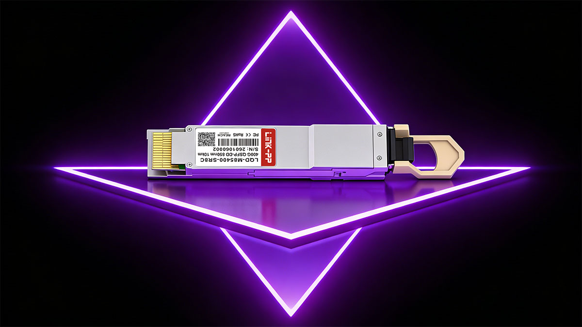
QSFP-DD (Quad Small Form-factor Pluggable Double Density) is an eight-lane pluggable optical module form factor designed to enable 400G and beyond while preserving a similar mechanical footprint to earlier QSFP modules. By doubling the electrical interface from four lanes to eight lanes, 400G Module allows network engineers to dramatically increase front-panel bandwidth without expanding switch size or port spacing.
Today, QSFP-DD has become one of the most widely adopted solutions for hyperscale data centers, AI cluster fabrics, and carrier-class aggregation networks.
↪️ What Is QSFP-DD?
QSFP-DD (Quad Small Form-factor Pluggable – Double Density) is an eight-lane pluggable optical transceiver form factor designed to scale Ethernet and data center interconnect bandwidth to 400G and emerging 800G speeds. It extends the traditional QSFP electrical interface from four lanes to eight lanes, effectively doubling the available bandwidth within the same compact footprint.
The term “double density” refers to this expanded electrical architecture. By adding a second row of high-speed electrical contacts, QSFP-DD delivers higher aggregate data rates while maintaining mechanical backward compatibility with existing QSFP+, QSFP28, and QSFP56 modules. This enables a smooth migration path for data center operators without requiring a complete redesign of switch ports or cabling infrastructure.
Key Characteristics of QSFP-DD
Eight high-speed electrical lanes for increased bandwidth density
Supports PAM4 and legacy NRZ modulation, depending on speed and application
Designed for 200G, 400G, and emerging 800G Ethernet deployments
Mechanical backward compatibility with QSFP+/QSFP28 modules
Optimized for hyperscale data centers and AI/ML infrastructure, where port density and power efficiency are critical
Today, QSFP-DD is widely adopted as the primary 400G pluggable optics platform in modern data center switching environments, forming the foundation for scalable cloud, AI, and high-performance computing networks.
↪️ What Problem Does QSFP-DD Solve?
As switch ASIC bandwidth rapidly increased beyond 12.8 Tbps, traditional QSFP28 modules—limited to four electrical lanes—became a scalability bottleneck.
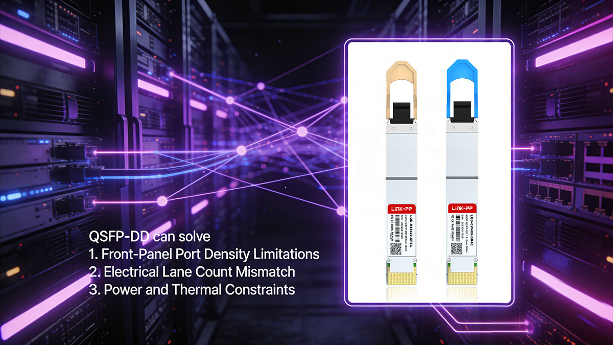
QSFP-DD addresses three fundamental challenges in modern high-speed network deployments:
1. Front-Panel Port Density Limitations
Conventional QSFP form factors restrict the amount of bandwidth that can be delivered per switch port. Increasing switch throughput without increasing chassis size requires higher bandwidth per port. QSFP-DD solves this by enabling 400G transmission while maintaining similar port dimensions.
2. Electrical Lane Count Mismatch
Next-generation ASICs support higher SerDes lane counts and speeds. QSFP-DD aligns with these platforms by expanding to eight electrical lanes, enabling efficient mapping between host ASIC lanes and optical interfaces.
3. Power and Thermal Constraints
Higher bandwidth requires increased digital signal processing (DSP) capability and forward error correction (FEC). 400G Transceiver is designed to support these requirements while balancing cooling and airflow constraints in high-density deployments.
By doubling the electrical interface to eight lanes, QSFP-DD enables 400G throughput without increasing front-panel footprint, allowing data centers to scale capacity within existing infrastructure constraints.
4. What Engineers Should Check Before Adopting QSFP-DD
Platform support: Confirm switch ASIC and firmware support for QSFP-DD electrical pinout and breakout modes.
Power budget: Verify per-port and chassis-level power headroom for worst-case module power.
Thermal plan: Validate airflow, fan curves, and temperature alarms under sustained traffic.
Signal integrity: Review host trace lengths and connector specifications; prefer short controlled impedance paths for PAM4 lanes.
Interoperability testing: Run vendor mutual testing (compatibility matrix, burn-in, and link-margin validation) before production rollout.
Monitoring: Ensure DOM/diagnostic telemetry for temperature, voltage, and optical power is supported and integrated into NMS/monitoring systems.
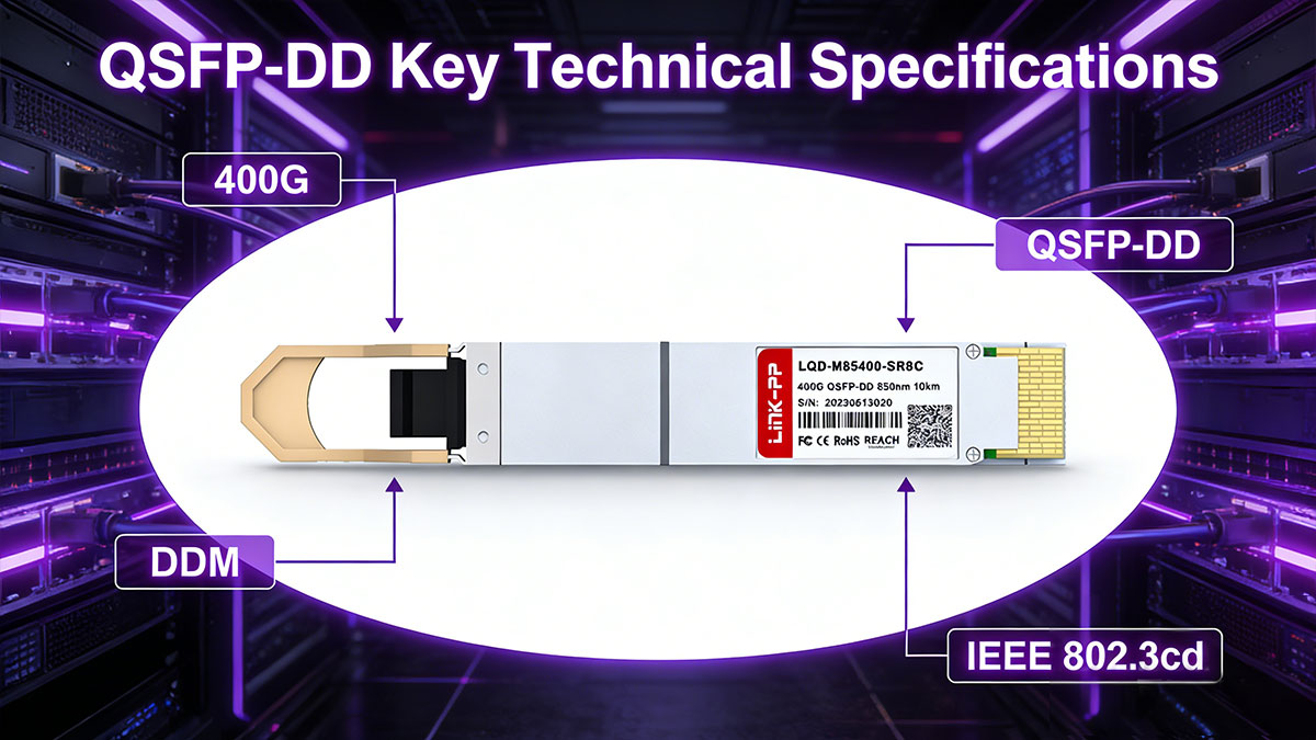
↪️ QSFP-DD Key Technical Specifications
400G QSFP-DD supports multiple lane speeds and modulation technologies to enable flexible high-speed interconnect designs.
Parameter | QSFP-DD |
|---|---|
Electrical Lanes | 8 |
Lane Speed | 25G / 50G PAM4 |
Aggregate Data Rate | 200G / 400G / 800G |
Modulation | NRZ (legacy), PAM4 |
Connector | QSFP-DD edge connector |
Backward Compatibility | QSFP+, QSFP28 (cage and adapter support) |
Typical Use | Data center spine-leaf switching |
Detailed Explanations and Practical Values
Electrical lanes & lane speed
What it is: QSFP-DD increases the number of high-speed electrical lanes presented to the host from 4 (QSFP28) to 8 lanes.
Practical lane speeds: 25G NRZ (legacy / slower links), 50G PAM4 (common for 400G), and 100G PAM4 (used for many 800G experiments/implementations).
Design impact: host PCB routing, connector quality, and SerDes configuration must support the chosen lane speed and signaling type.
Aggregate data rates
How aggregate is formed: aggregate rate = (lane count) × (lane speed). Example: 8 × 50G = 400G.
Common aggregates: 200G (e.g., 8 × 25G), 400G (8 × 50G), 800G (8 × 100G or other lane aggregations).
Modulation (NRZ vs. PAM4)
NRZ (non-return to zero): simpler, used historically at 10/25/28G per lane.
PAM4 (4-level pulse amplitude modulation): doubles bits per symbol vs NRZ, enabling 50G/100G per lane with the same baud but requires advanced DSP, stronger equalization, and more robust FEC.
Practical consequence: PAM4 increases module complexity, power, and requirements for channel SNR and equalization.
Connector and mechanical form factor
QSFP-DD connector: uses a dual-row (double density) contact array in a QSFP-sized cage to carry 8 high-speed lanes.
Mechanical compatibility: many QSFP-DD cages accept QSFP28/QSFP+ modules mechanically, but functional compatibility depends on host PCB wiring and firmware support (see compatibility section).
Backward compatibility caveat
Mechanical vs functional: QSFP-DD cage is intentionally designed to accept older QSFP form factor mechanically, but you must verify that the host board / ASIC / firmware support the electrical mapping and speed negotiation required for older modules.
Breakout behavior: some platforms support breakout modes (e.g., 1×400G → 4×100G), but this depends on ASIC and firmware implementations.
Power consumption (typical ranges)
QSFP28 100G: ~3.5–4.5 W (reference point)
QSFP-DD 400G: typical production modules commonly draw ~10–14 W; design for worst-case (manufacturer maximal spec) when planning power/thermal budgets.
800G QSFP-DD: early chips/modules may draw 16–20 W or higher.
Design note: use worst-case/per-module power for chassis power supply and thermal planning; transient and sustained loads both matter.
Optical interfaces and reach (typical 400G mappings)
SR8 (MMF): short-reach, typically up to ~100 m over OM4/OM5 multimode fiber using MPO/MTP.
DR4 (SMF): ~500 m single-mode (4×100G lanes or equivalent).
FR4 (SMF): ~2 km class.
LR4 (SMF): ~10 km class.
(Actual reach depends on vendor optics, fiber type, link budget, connector/splice losses, and FEC.)
Diagnostics and management
DDM/DOM: QSFP-DD modules expose digital diagnostics (I²C accessible) for temperature, supply voltage, laser bias, Tx/Rx optical power, etc. Integrate telemetry into NMS for proactive monitoring.
Telemetry best practice: set conservative alarm/critical thresholds and validate against thermal throttling behavior.
Signal integrity and channel design
Channel sensitivity: 8 lanes at PAM4 magnify signal-integrity requirements—controlled impedance routing, minimized trace lengths, careful via stubs, and high-quality connectors are essential.
DSP/FEC role: on-module DSP and FEC compensate for channel impairments but cannot replace proper channel engineering.
Standards and ecosystem
MSAs & IEEE: QSFP-DD mechanical/electrical details are defined in the QSFP-DD MSA (multi-source agreement); 400G optical PHYs and PMDs are defined in IEEE 802.3 (e.g., 400GBASE specs). Use MSA documents and IEEE standards as authoritative references when validating designs and claims.
What to Verify for Each QSFP-DD Module
Lane configuration: confirm lane count & lane speed (e.g., 8 × 50G PAM4).
Power class: check typical and max power dissipation; plan chassis power/PSU accordingly.
Thermal envelope: validate module thermal dissipation and host airflow requirements.
Optical interface & reach: SR8/DR4/FR4/LR4 mapping and link budget (Tx/Rx powers, receiver sensitivity).
FEC & DSP: check required FEC mode and any latency implications.
Compatibility: confirm host ASIC support, breakout modes, and firmware compatibility.
Signal integrity: review host trace length, connector/cage spec, and required SerDes equalization settings.
Telemetry: ensure DOM/DDM I²C mapping and NMS integration.
Interoperability testing: run platform burn-in and mutual link tests under worst-case thermal/power conditions.
↪️ QSFP-DD Electrical Architecture Explained
QSFP-DD (Quad Small Form Factor Pluggable – Double Density) achieves higher port bandwidth by doubling the electrical lane count from 4 to 8 within the same QSFP form factor. This architectural change allows next-generation switch ASICs to scale beyond 100G without increasing front-panel width.
♦ Lane Layout Comparison
Form Factor | Electrical Lanes | Typical Speed |
|---|---|---|
QSFP+ | 4 × 10G | 40G |
QSFP28 | 4 × 25G | 100G |
QSFP-DD | 8 × 25G / 50G | 400G / 800G |
Engineering note: Most deployed 400G modules use 8 × 50G PAM4 lanes.
♦ How Double Density is Achieved
QSFP-DD Transceiver introduces a second row of high-speed electrical contacts inside the connector while maintaining the familiar QSFP cage dimensions. This enables:
Direct electrical alignment with 8-lane switch ASIC SerDes
Higher per-port bandwidth without reducing front-panel port count
Mechanical compatibility with legacy QSFP cages (with host support)
♦ Architectural Implications
Doubling lane density and adopting PAM4 modulation has several system-level consequences:
Higher signal integrity sensitivity due to increased lane count and channel loss
Mandatory DSP and FEC to compensate for PAM4’s reduced noise margin
Increased power dissipation, impacting thermal and airflow design
These factors make 400G Modules integration more demanding than QSFP28 and require careful host PCB, power, and cooling design.
♦ Why this Architecture Matters
QSFP-DD’s electrical architecture bridges the gap between rapidly scaling switch ASIC bandwidth (≥12.8 Tbps) and practical front-panel density. It enables 400G—and lays the electrical foundation for 800G—without forcing disruptive mechanical redesigns.
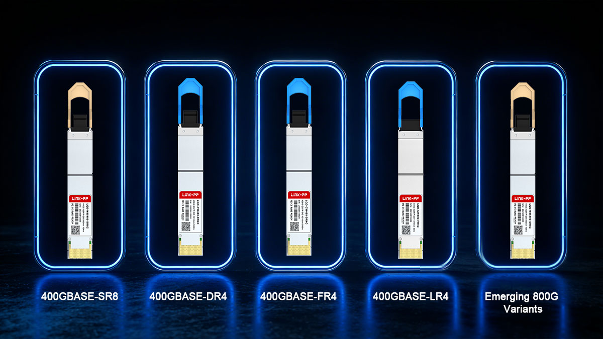
↪️ 400G QSFP-DD Module Types
QSFP-DD supports multiple optical interface standards optimized for different transmission distances and fiber infrastructures.
Quick Reference Table
Module Type | Fiber Type | Typical Reach (vendor dependent) | Typical Connector | Lane Count / Aggregation | Typical Use |
|---|---|---|---|---|---|
400GBASE-SR8 | Multimode (OM3/OM4/OM5) | ~100 m | MPO/MTP (parallel) | 8 × 50G (parallel) | In-rack, short-reach leaf/spine links |
400GBASE-DR4 | Single-mode (SMF) | ~500 m | MPO/MTP or multiple LC (vendor) | 4 × 100G or 8 × 50G mapping (vendor dependent) | Data-center inter-rack, campus aggregation |
400GBASE-FR4 | Single-mode (SMF) | ~2 km | LC (usually duplex per channel or MPO) | 4 × (sub-aggregates) — PHY mapping per standard | Metro links, longer DC interconnects |
400GBASE-LR4 | Single-mode (SMF) | ~10 km | LC (duplex / WDM) | 4 λ WDM or equivalent aggregation | Metro edge, regional aggregation |
800GBASE-DR8 / FR8 (emerging) | SMF / MMF variants | DR8: similar short-to-mid; FR8: longer | MPO / LC (vendor dependent) | 8 × 100G or 16 × 50G (vendor dependent) | Hyperscale trunking, future high-density fabrics |
Note: reach numbers above are typical planning values. Actual link reach depends on vendor optical power (Tx), receiver sensitivity, fiber type, connector/splice losses, and FEC employed. Always verify vendor datasheets and run a link-budget calculation for your specific fiber plant.
400GBASE-SR8
Multimode fiber (MMF)
Short-reach data center interconnects
Typically deployed using MPO/MTP connectors
400GBASE-DR4
Single-mode fiber (SMF)
Up to approximately 500 meters
Commonly used in hyperscale spine-leaf fabrics
400GBASE-FR4
Single-mode fiber
Up to approximately 2 kilometers
Uses WDM technology with duplex LC connectors
400GBASE-LR4
Single-mode fiber
Up to approximately 10 kilometers
Typically used for metro or campus aggregation links
Emerging 800G Variants
800GBASE-DR8
800GBASE-FR8
These emerging standards extend 800G module capability using higher PAM4 lane speeds, though power and thermal requirements remain key engineering considerations.
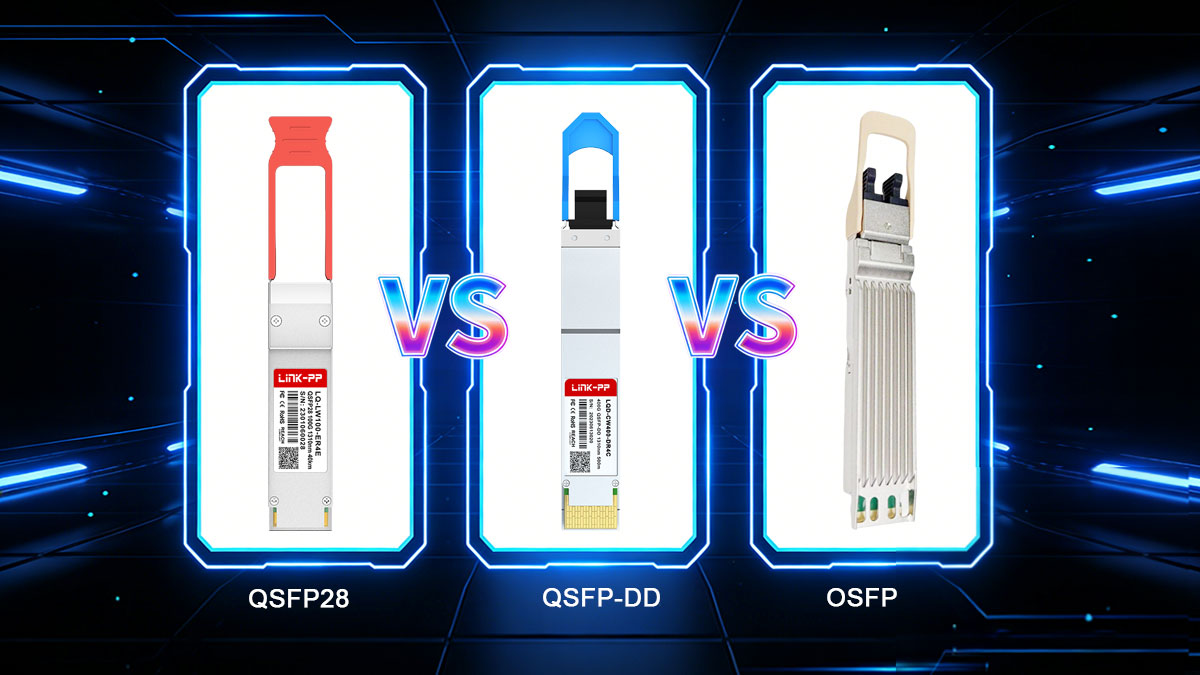
↪️ QSFP-DD vs. QSFP28 vs. OSFP — Power, Thermal, and Backward-compatibility
This section compares the three common high-speed pluggable ecosystems, summarizes power/thermal consequences of moving to QSFP-DD/800G, and lists the concrete compatibility constraints engineers must verify before deployment.
Power Consumption — Typical Per-module Ranges
(use vendor max specs for final power/PSU planning; these are typical production ranges used for preliminary capacity planning)
Module type | Typical power (per module) |
|---|---|
QSFP28 (100G) | 3.5–4.5 W |
QSFP-DD (400G) | ~10–14 W |
QSFP-DD (800G, early) | ~16–20 W |
Engineering note: always design chassis power and thermal headroom to accommodate worst-case module power (manufacturer max), sustained load, and transient scenarios (boot/peak traffic).
Practical Engineering Impacts of Higher Per-port Power
Switch airflow direction becomes critical. Different vendors use front-to-back or back-to-front airflow; module cooling effectiveness depends on matching module thermal path to chassis airflow.
Port placement strategy affects thermal throttling. Concentrating high-power modules in adjacent ports can create hot spots and trigger thermal throttling; distribute high-power ports or provision additional cooling.
DOM temperature monitoring is mandatory. Integrate DOM/DDM telemetry into NMS for active alarms and trending; temperature thresholds should drive automated mitigation (rate limiting, fan stage changes, or module replacement).
Practical actions
Use vendor max power for per-port and whole-chassis power budgeting.
Run thermal chamber tests with fully populated worst-case modules.
Validate fan control curves under worst-case ambient and sustained load.
Implement telemetry dashboards that correlate port power, temperature, and error counts.
Backward Compatibility — What Works and What Doesn’t
QSFP-DD cages are mechanically designed to accept older QSFP form factors (QSFP+ and QSFP28). However:
Mechanical fit ≠ functional compatibility. A QSFP28 inserted into a QSFP-DD cage will physically seat, but the host ASIC, PCB routing, and firmware must support the older module’s electrical mapping and speed negotiation.
Backward modules run at their native speed only. A QSFP28 cannot magically operate at 400G when placed in a QSFP-DD cage.
Electrical lane mapping differs. Breakout logic, lane ordering/polarity, and SerDes configuration must be supported by the switch ASIC and firmware for correct operation.
Power & cooling profiles differ significantly. Expect higher per-port cooling needs for QSFP-DD/800G; older QSFP28 power assumptions can be invalid when mixed with QSFP-DD in the same chassis.
Checklist before mixing module types
Confirm host ASIC and firmware support for mixed form factors and breakout modes.
Verify board routing and power distribution accommodate both module classes.
Test mechanical insertion/removal and DOM reporting for each supported module type.
Update NMS to recognize and handle differing DOM registers and thresholds.
Quick Comparison: QSFP28 vs. QSFP-DD vs. OSFP
Feature | QSFP28 | QSFP-DD | OSFP |
|---|---|---|---|
Max speed (typical) | 100G | 400G / 800G | 800G |
Electrical lanes | 4 | 8 | 8 |
Backward compatibility | N/A (legacy) | Mechanical: yes; Functional: conditional | No (different mechanical footprint) |
Power headroom | Limited | Medium | High |
Primary ecosystem | Mature broad market | Hyperscale & mainstream DC | Hyperscale (power-heavy platforms) |
Interpretation: QSFP-DD strikes a pragmatic balance — it delivers higher density while preserving mechanical continuity for much of the QSFP ecosystem. OSFP offers higher power headroom (favored by some hyperscalers) but requires different cages and front-panel real estate.
Engineering Takeaway
QSFP-DD is the most pragmatic path for many data centers to reach 400G without a full mechanical redesign. But it raises electrical, power, and thermal requirements that must be validated at the platform level:
Plan for worst-case power and thermal loads, not typical values.
Treat mechanical compatibility as only the first step — validate functional compatibility (ASIC, firmware, lane mapping).
Integrate DOM telemetry and automated thermal mitigation into operations.
If you want, I can produce a short thermal-budget worked example (per-chassis power & fan profile) using a 32×400G QSFP-DD configuration, or generate a compatibility checklist you can hand to hardware validation teams. Which would help you next?
↪️ Typical QSFP-DD Deployment Scenarios
QSFP-DD is primarily deployed where port density, bandwidth scaling, and forward compatibility are critical. Below are the most common real-world scenarios, with practical engineering context rather than marketing generalities.
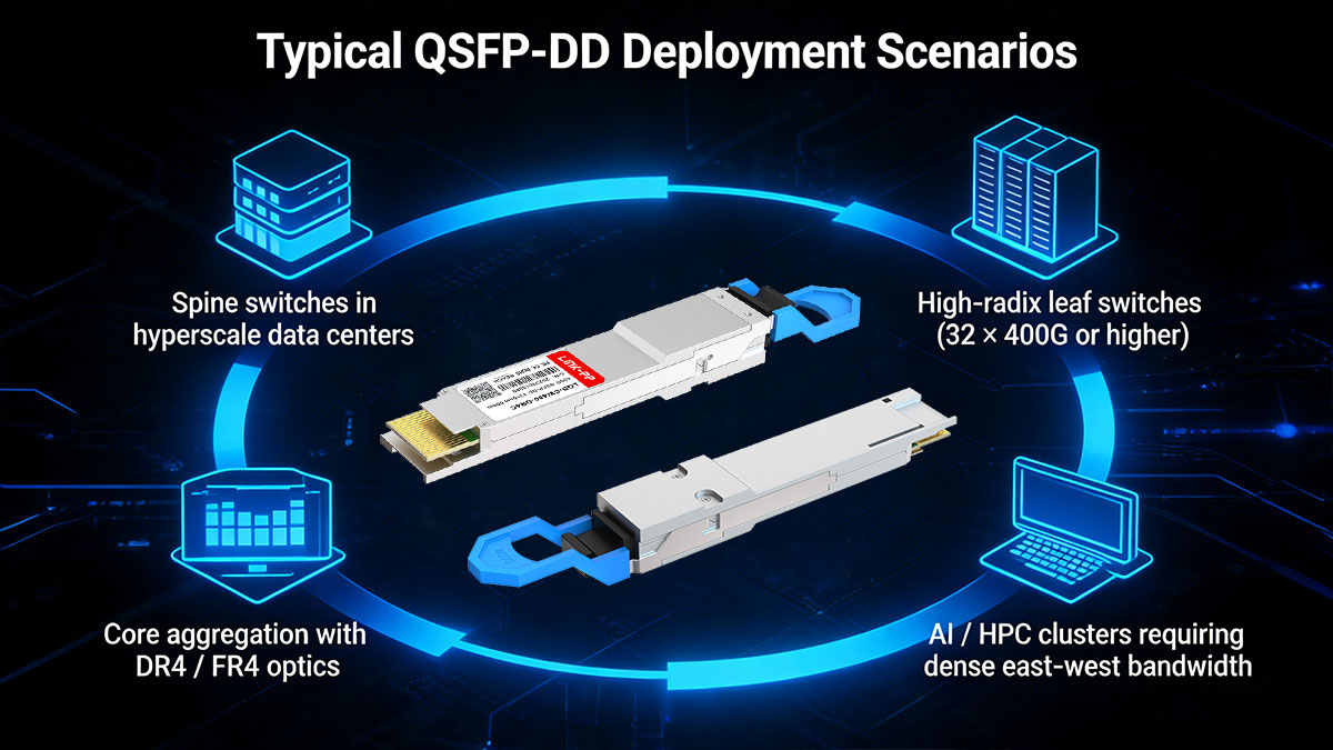
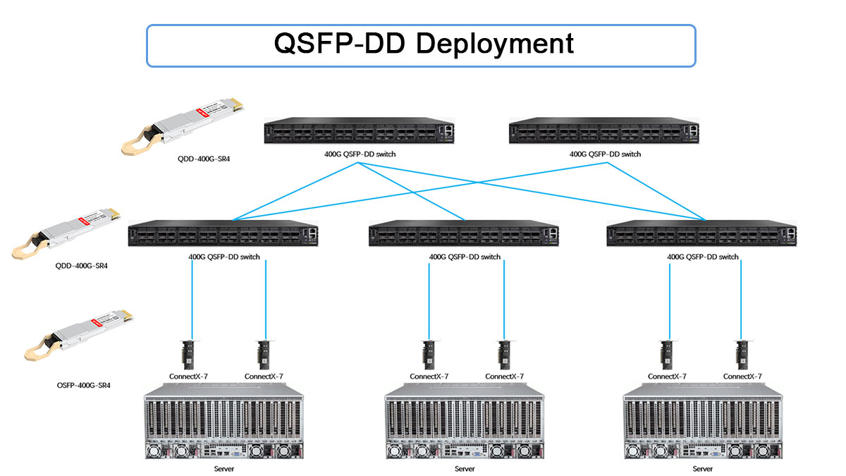
▶ Spine switches in hyperscale data centers
QSFP-DD is the dominant form factor for 400G spine layers in hyperscale and large cloud data centers.
Enables massive east-west bandwidth between leaf tiers without increasing rack count
Aligns cleanly with ≥12.8 Tbps and 25.6 Tbps switch ASICs
Commonly paired with 400GBASE-DR4 or FR4 optics depending on fabric reach
Why QSFP-DD fits: high port density, standardized ecosystem, and mechanical continuity with QSFP-based platforms simplify large-scale rollout and spares management.
▶ High-radix leaf switches (32 × 400G or higher)
Modern leaf switches increasingly use high-radix QSFP-DD front panels (for example, 32 × 400G or 64 × 400G designs).
Reduces the number of leaf devices needed for the same fabric capacity
Simplifies cabling and lowers operational complexity
Supports breakout modes (e.g., 400G → 4 × 100G) when ASIC and firmware allow
Design note: power density and airflow planning are essential, especially when many adjacent ports are populated with ≥12 W modules.
▶ AI / HPC clusters requiring dense east-west bandwidth
AI training and HPC workloads generate extremely high east-west traffic, making QSFP-DD a natural choice.
Supports high-bandwidth, low-latency fabrics for GPU/accelerator clusters
Commonly used with short-reach DR4 or SR8 optics inside AI pods
Provides a migration path toward 800G without changing mechanical form factor
Operational consideration: tight thermal margins and sustained high utilization require proactive DOM temperature monitoring and strict cooling validation.
▶ Core aggregation with DR4 / FR4 optics
QSFP-DD is also widely used at core or aggregation layers where 400G links consolidate multiple lower-speed connections.
DR4 (~500 m) suits large campuses or multi-hall data centers
FR4 (~2 km) enables metro-adjacent aggregation without coherent optics
Reduces fiber count and port complexity compared with multiple 100G links
Planning tip: always validate link budgets and FEC requirements, especially for FR4 and longer reaches, to avoid marginal links at scale.
▶ Deployment Summary (When QSFP-DD Makes Sense)
QSFP-DD is best suited for environments that require:
400G bandwidth per port today, with a path to 800G
High front-panel density without mechanical redesign
Standardized optics across spine, leaf, and aggregation layers
For lower-density or power-constrained platforms, QSFP28 may remain sufficient. For ultra-high-power hyperscale designs, OSFP may be considered — but QSFP-DD remains the most balanced and widely adopted option across the industry.
↪️ QSFP-DD Selection and Deployment Best Practices
Selecting and deploying QSFP-DD modules is not just a speed decision — it’s a system-level engineering exercise involving optics, ASIC capability, power, thermal design, and long-term operability. The practices below reflect what consistently works in real data center and AI/HPC deployments.
1. Start With the Link, Not the Module
Always select the optical standard based on reach and fiber plant, then choose a compatible QSFP-DD module.
≤100 m, MMF available: 400GBASE-SR8
≤500 m, SMF: 400GBASE-DR4
≤2 km, SMF: 400GBASE-FR4
≤10 km, SMF: 400GBASE-LR4
Best practice: run a formal link budget using vendor Tx(min), Rx(max), connector/splice losses, and a ≥2–3 dB engineering margin.
2. Verify Host ASIC and Firmware Support
4OOG Module functionality depends heavily on host-side capabilities.
Confirm the following before purchase or deployment:
Supported electrical lane rates (8 × 50G PAM4 vs legacy modes)
Supported breakout options (e.g., 400G → 4 × 100G)
Required FEC types and defaults
DOM/DDM register compatibility and telemetry reporting
Field lesson: many “compatibility issues” are firmware limitations, not optical failures.
3. Design for Worst-case Power and Thermal Load
QSFP-DD modules operate at significantly higher power than QSFP28.
Budget using maximum rated power, not typical values
Validate airflow direction (front-to-back vs back-to-front)
Avoid clustering high-power optics in adjacent ports
Confirm fan curves and thermal alarms under sustained traffic
Rule of thumb: if a platform is stable at idle but fails under load, thermal headroom is insufficient.
4. Treat Backward Compatibility As Conditional
While QSFP-DD cages accept QSFP+/QSFP28 mechanically, functional compatibility is not guaranteed.
Backward modules operate at native speed only
Lane mapping and polarity must be supported by the switch
Mixed deployments require careful firmware validation
Cooling assumptions differ between 100G and 400G optics
Best practice: test mixed module configurations in a staging environment before production rollout.
5. Standardize Optics to Reduce Operational Complexity
At scale, consistency matters more than theoretical flexibility.
Limit the number of module SKUs per reach class
Standardize connector types (MPO vs. LC) per layer
Align vendor selection with support, firmware cadence, and lead time reliability
This reduces sparing requirements, troubleshooting time, and field errors.
6. Make DOM Monitoring Part of Operations, Not Diagnostics
DOM/DDM telemetry should be continuously monitored, not checked only during failures.
Track at minimum:
Module temperature
Tx/Rx optical power
Supply voltage and bias current
Actionable insight: trending DOM data often reveals fiber degradation or cooling issues weeks before link failure.
7. Plan for Forward Scalability (400G → 800G)
Even if deploying 400G today, plan with the next generation in mind.
Confirm cage and connector readiness for higher power modules
Validate power and airflow margins for early 800G QSFP-DD optics
Avoid locking into optics that block future lane-rate upgrades
Strategic advantage: QSFP-DD 400G allows incremental scaling without reworking front-panel mechanics.
8. Deployment Checklist
✅ Optical standard matches reach and fiber plant
✅ Link budget validated with margin
✅ Host ASIC + firmware compatibility confirmed
✅ Power and thermal headroom verified at full load
✅ Mixed-module scenarios tested
✅ DOM telemetry integrated into NMS
✅ Upgrade path to 800G considered
↪️ 400G QSFP-DD Transceiver FAQs
Q1: What does QSFP-DD stand for?
QSFP-DD stands for Quad Small Form-factor Pluggable – Double Density, referring to its doubled electrical lane count.
Q2: Is QSFP-DD the same as QSFP56-DD?
QSFP56-DD is an early naming variant. In practice, both refer to QSFP-DD supporting 50G PAM4 lanes.
Q3: Can QSFP-DD support 800G?
Yes. Early 800G QSFP-DD modules use 8 × 100G PAM4, but power and thermal constraints remain challenging.
Q4: Does QSFP-DD require new fiber infrastructure?
Not always. DR4 and FR4 reuse existing single-mode fiber, though connector type (MPO vs LC) may change.
Q5: Is QSFP-DD suitable for enterprise networks?
Generally no. QSFP-DD targets hyperscale data centers and carrier-class aggregation, not typical enterprise access networks.
↪️ QSFP-DD Conclusion and Final Recommendations
QSFP-DD has emerged as the primary 400G form factor not because it is simply faster than QSFP28, but because it enables a step-change in bandwidth density without expanding switch front-panel real estate. By doubling the electrical interface to eight lanes, QSFP-DD aligns optics capability with next-generation switch ASIC bandwidth growth.
That said, QSFP-DD introduces new engineering constraints. Higher lane density, PAM4 signaling, and increased per-port power fundamentally shift deployment priorities toward signal integrity, thermal design, firmware maturity, and platform validation. Treating 400G module as a drop-in replacement rather than a system-level upgrade is a common source of instability in early deployments.
QSFP-DD enables 400G and beyond without increasing front-panel footprint
PAM4 and higher lane density tighten signal integrity and thermal margins
Backward compatibility is mechanical, not automatically functional
Interoperability and validation testing are essential for production networks
Final Recommendations
Engineers evaluating QSFP-DD Modules should:
Start with the switch platform, not the optic—verify ASIC support, airflow direction, and power budget
Validate under worst-case conditions, including full port population and sustained traffic
Standardize optics and cabling architectures to reduce operational complexity
Actively monitor DOM telemetry, especially temperature and optical power
Plan for future scaling, ensuring today’s 400G decisions do not constrain 800G roadmaps
QSFP-DD is not just a faster QSFP—it represents a fundamental shift in port density strategy for modern data centers, AI clusters, and carrier-class networks. Success depends less on headline speed and more on system-level compatibility and operational discipline.
Explore QSFP-DD Solutions from LINK-PP
For validated QSFP-DD 400G optical module designed for spine–leaf architectures, AI/HPC clusters, and high-density aggregation, visit the LINK-PP Official Store.
LINK-PP provides detailed specifications, compatibility guidance, and production-ready QSFP-DD optics to support reliable, large-scale deployments.
See Also
QSFP-DD Optical Transceivers Enabling High-Speed Connections
Advantages of Using the 100G SFP-DD LR Transceiver
Improving High-Density Networks with 100G SFP-DD Transceivers


