
In high-speed digital communications—where data rates are pushing 25 Gbps, 50 Gbps, and beyond—the integrity of the transmitted signal is constantly challenged by the physical channel (PCB traces, copper cables). This challenge manifests primarily as Intersymbol Interference (ISI).
ISI occurs when the energy from a currently transmitted data symbol "spills over" and interferes with the sampling of subsequent symbols. This phenomenon, which degrades the eye diagram by closing both its height and width, is the primary cause of an elevated Bit Error Rate (BER).
While the Continuous-Time Linear Equalizer (CTLE) is highly effective at compensating for the frequency-dependent attenuation (channel loss), it can introduce noise enhancement. For maximum performance and the elimination of residual, long-tail ISI, a more sophisticated, nonlinear solution is required: the Decision Feedback Equalizer (DFE).
⭐ What Is a Decision Feedback Equalizer (DFE)?
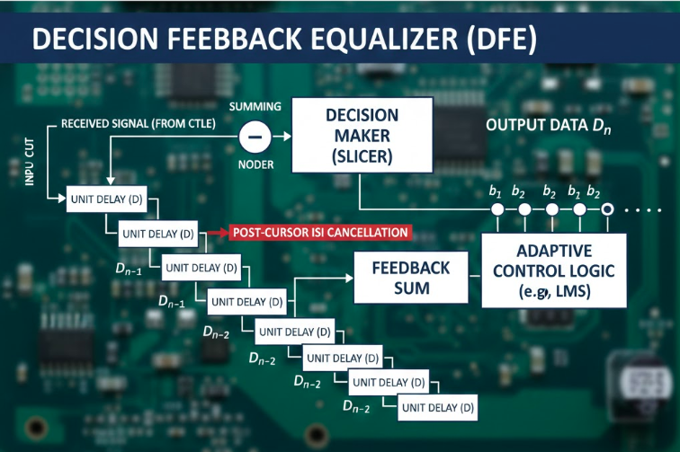
A Decision Feedback Equalizer (DFE) is a digital or mixed-signal equalization technique used in high-speed serial links and optical transceivers to remove post-cursor inter-symbol interference (ISI).
Unlike linear equalizers such as CTLE, which operate in the analog domain, DFE works after the signal has been sliced into digital symbols, using previous symbol decisions to cancel distortion caused by earlier bits interfering with later ones.
DFE has become a critical block in modern SerDes receivers and optical modules (including SFP+, SFP28, QSFP28, and 100G/200G/400G transceivers).
⭐ Why DFE Is Needed — Understanding Post-Cursor ISI
▷ What Is ISI?
Inter-symbol interference occurs when limited channel bandwidth, reflections, or dispersion cause one bit’s waveform tail to spill into the next bit period.
▷ Post-Cursor ISI (Core Problem DFE Solves)
Post-cursor ISI is the distortion caused by previous bits interfering with the current bit at the receiver sampling point.
This distortion:
shrinks eye-diagram height
shifts decision thresholds
increases bit-error rate (BER)
cannot be fully corrected by analog equalizers like CTLE
▷ Why High-Speed Links Need DFE
As data rates scale to 25G, 50G, 100G PAM4 and beyond, channel latency and bandwidth limitations make post-cursor ISI much more severe.
DFE is the most effective technique for cancelling this specific form of distortion because:
It adapts based on actual decisions
It does not amplify noise or high-frequency jitter
This makes DFE indispensable for modern high-speed optical-module receivers.
▷ DFE in High-Speed Optical Transceivers
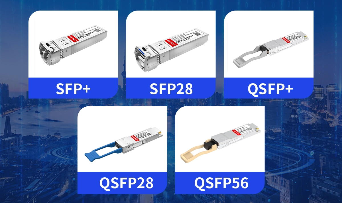
Optical modules such as SFP+, SFP28, QSFP+, QSFP28, QSFP56, and 100G-PAM4 modules integrate DFEs in the DSP or SerDes receiving chain to ensure error-free operation under fiber dispersion, PCB loss, and connector reflections.
DFE helps restore eye opening after optical-to-electrical conversion and plays a crucial role in meeting IEEE 802.3 electrical specifications.
⭐ CTLE vs DFE — Complementary Equalization Roles
Why CTLE Alone Is Not Enough
CTLE (Continuous-Time Linear Equalizer):
fixes frequency-dependent loss
boosts high-frequency components
works in the analog front-end
But CTLE cannot cancel nonlinear ISI.
Why DFE Complements CTLE Perfectly
DFE:
removes post-cursor ISI
operates after digitization
does not boost noise
This makes CTLE + DFE the most widely used hybrid equalization scheme in modern SerDes and optical modules.
⭐ Advantages and Limitations of DFE
● Advantages
Highly effective at cancelling post-cursor ISI
Does not amplify thermal or channel noise
Adaptive and robust to channel variations
Improves BER dramatically in multi-gigabit links
● Limitations
Cannot correct pre-cursor ISI (FFE/Tx pre-emphasis required)
Feedback loop increases complexity and power consumption
Requires accurate and stable decisions (error propagation is a risk)
More complex implementation at PAM4 rates
⭐ Practical Use Cases of DFE in Industry
Applications
Backplane links (25G/56G/112G SerDes)
High-speed Ethernet (25GBASE-KR, 100GBASE-KR4)
PCIe Gen4/5/6
Optical module DSPs (10G–400G)
CDR / Retimer ICs
High-density switch and router ports
Why It Matters in Optical Modules
DFE helps meet stringent signal integrity and BER requirements across diverse channel conditions — fiber lengths, connector variations, PCB geometries — making it vital in 100G/200G/400G optical platforms.
⭐ Summary
A Decision Feedback Equalizer (DFE) is a critical digital equalization technique used in high-speed communication systems to remove post-cursor ISI — a major contributor to signal distortion at multi-gigabit data rates.
By using past symbol decisions to cancel interference dynamically, DFE significantly improves eye opening and BER performance, especially when combined with CTLE or Tx-side FFE.
In modern optical modules and SerDes receivers, CTLE handles linear analog loss, while DFE corrects nonlinear digital ISI, forming the industry-standard hybrid equalization architecture.


