
As data rates soar to 10 Gbps, 25 Gbps, and beyond in network switches, servers, and storage systems, the physical channel connecting chips and modules introduces a fundamental obstacle: channel loss. This loss, primarily due to skin effect, dielectric absorption, and impedance discontinuities in PCB traces or copper cables, acts as a low-pass filter.
This filtering action severely attenuates the high-frequency components of the transmitted signal. The result is a degraded eye diagram, characterized by a reduced eye height and significant intersymbol interference (ISI). Without aggressive compensation, reliable data recovery becomes impossible.
This is where the Continuous-Time Linear Equalizer (CTLE), a vital component in modern serializer/deserializer (SerDes) architectures, steps in.
➡️ What is a CTLE?
A Continuous‑Time Linear Equalizer (CTLE) is an analog equalization circuit used in the receiver front-end of high-speed data links — such as SerDes channels or optical‑module receivers — to compensate for frequency‑dependent channel losses that degrade signal integrity.
Unlike digital equalizers, CTLE works in the analog domain: it adjusts the frequency response of the received analog signal before any clock recovery or symbol decision, boosting attenuated high‑frequency components and suppressing excessively dominant low‑frequency components.
➡️ Why CTLE is Needed
1. Channel Loss in High-Speed Links
In real-world high‑speed channels — whether a copper trace, a backplane routing, or an optical-electrical interface in optical modules — the physical medium exhibits frequency‑dependent loss: higher-frequency components (which carry the sharp transitions and edges of digital waveforms) suffer greater attenuation than lower‑frequency components. This results from effects such as skin effect, dielectric loss, impedance mismatches, and general frequency‑dependent insertion loss.
As a result, after transmission, the received waveform’s edges become less sharp, the amplitude is reduced, and the “eye diagram” used to visualize signal integrity may collapse (eye closure), leading to increased inter-symbol interference (ISI) and degraded bit‑error rate (BER).
2. Restoring Signal Integrity via Equalization
To counteract this, receivers employ equalization — the goal being to “undo” the channel’s filtering effect and restore a balanced frequency response. CTLE implements a form of high‑pass (or peaking) filter in the analog domain: boosting high-frequency components while attenuating or leaving low-frequency components relatively untouched (or even suppressed).
In practice, that means after CTLE processing, the combined response of “channel + CTLE” becomes more uniform across the relevant frequency band (i.e., closer to an all‑pass response), improving edge sharpness, recovering eye opening, mitigating ISI, and making timing recovery (clock/data recovery) more reliable — all before any digital equalization or decision logic.
3. A Note for Optical Module Engineers
As data rates continue climbing — 100G, 200G, 400G and beyond — channel impairments (loss, dispersion, coupling, PCB/reflection, fiber/electrical transitions) only become more severe. Equalization is no longer optional; it is foundational.
For companies like LINK‑PP focusing on optical transceivers, ensuring your RX front‑end supports robust CTLE (and optionally DFE) is critical to guarantee reliability, low BER, and compatibility across varying fiber types (MMF / SMF), cable lengths, PCB traces, and connector types.
Moreover, for marketing and technical content: explaining that your modules integrate proven equalization technologies such as CTLE (and optionally DFE) helps boost customer trust and aligns with modern industry expectations.
➡️ How CTLE Works
● Transfer Function — Peaking Behavior in Frequency Domain
CTLE’s behavior is typically described via its frequency‑domain transfer function. In simplest form, a passive (or active) RC (or R‑C/L‑C) network provides a high-pass/peaking response. The net effect is to apply more gain at higher frequencies than at lower frequencies, counterbalancing the channel’s low-pass tendency.
In implementation, a CTLE may consist of a combination of resistors (R), capacitors (C), possibly inductors (L), and amplifying stages — either as a passive circuit or as an active equalizer with gain control.
The “peaking” (or “zero/pole”) in the transfer function is often tuned such that the equalizer’s boosted frequency range aligns with the critical frequency band of the data signal (e.g., up to the Nyquist frequency of the SerDes bit rate) to maximize effective compensation.
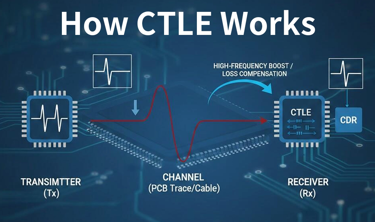
●Integration in Receiver Front-End (RX)
In a typical SerDes or optical‑module receiver architecture, the CTLE is placed immediately at the analog input stage (after coupling capacitors, if any), before any clock‑data recovery (CDR) or digital sampling.
This ensures the recovered signal has sufficiently fast edges and amplitude for reliable clock/data recovery. After CTLE and CDR, further equalization (e.g,. digital equalization, non‑linear equalizers such as Decision‑Feedback Equalizer, DFE) can be applied to mitigate residual ISI.
➡️ CTLE in Practice — Where It’s Used & Its Advantages and Trade‑Offs
▷ Applications: SerDes, High-Speed Optical Modules
CTLE is widely used in high-speed serial interfaces (SerDes), e.g., PCIe, USB, backplane links — and just as importantly, in high-speed optical communications, where optical-to-electrical conversion, fiber dispersion, cable loss, and transceiver packaging all contribute to frequency-dependent loss.
In optical modules, CTLE helps ensure that signals — after passing through fiber, transceiver front‑end, PCB traces, and connectors — still present clean, high‑quality waveforms at the receiver, enabling reliable high-bandwidth data transmission (100 G, 200 G, 400 G, etc.).
★ CTLE in LINK-PP Optics Transceivers
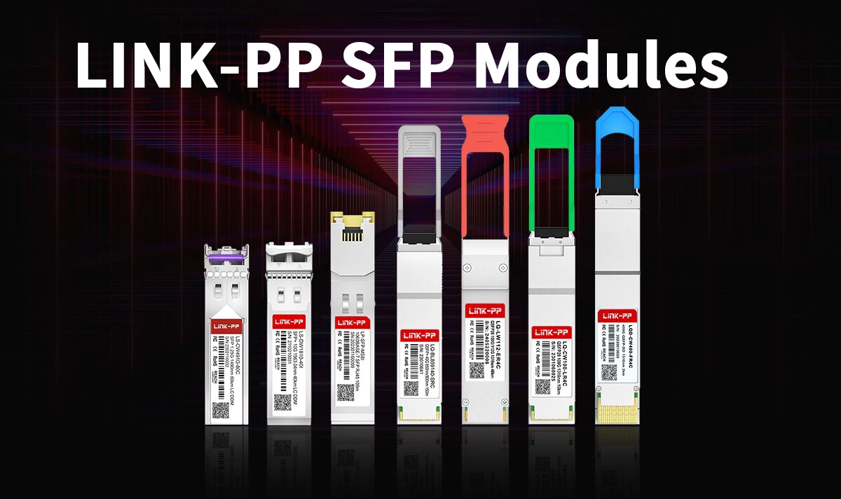
The reliability of high-speed connectivity products such as LINK-PP SFP Modules directly depends on robust equalization technology.
Optics Transceivers, particularly those operating at 10G/25G/100G and above (e.g., SFP+, QSFP28), often utilize a high-performance CTLE on both the electrical input (receiving data from a host card) and sometimes on the laser driver/TIA.
Receiving Data from Host (Input): The CTLE compensates for the loss incurred on the PCB traces between the host processor/switch chip and the SFP cage. The quality of this CTLE directly impacts the maximum trace length the module can reliably support.
Driving the Laser/TIA (Output): While the main loss compensation is at the receiver, the ability of the driver circuit (often including FFE) to interface seamlessly with the CTLE of the connected equipment is essential for a compliant and interoperable link.
By employing advanced, often adaptive CTLE technology, LINK-PP's SFP solutions ensure that the integrity of the data stream is maintained even across extended or challenging electrical interfaces, guaranteeing low BER and high system reliability.
▷ Advantages of CTLE
Low complexity & low power: As an analog circuit, CTLE can be relatively simple and power-efficient compared with fully digital equalizers (especially at very high speeds).
Immediate compensation in the analog domain: CTLE corrects for channel loss before clock/data recovery, making subsequent digital processing more robust.
Improved signal integrity: By boosting high-frequency components, CTLE helps reopen “closed eyes,” reduce ISI, and lower bit error rate (BER).
▷ Trade‑offs and Limitations
Noise amplification: Because CTLE boosts high-frequency components, it may also amplify high-frequency noise present on the channel.
Limited compensation range: CTLE alone may not fully eliminate all ISI or non-linear distortions — residual ISI, reflections, crosstalk, or channel mismatch may remain, requiring additional equalization (e.g., digital DFE).
Fixed or limited adaptability: Passive or simple active CTLEs may have limited ability to adapt dynamically to changing channel conditions, compared to adaptive digital equalizers.
➡️ CTLE vs. Other Equalization Techniques
While the Continuous-Time Linear Equalizer (CTLE) is a powerful linear equalizer, it is rarely used alone in modern high-speed communication systems. Different equalization techniques serve complementary roles across the transmitter (Tx) and receiver (Rx) chain to ensure robust signal integrity.
Equalizer | Location | Key Function | Benefit |
|---|---|---|---|
CTLE (Continuous-Time Linear Equalizer) | Rx Front-End | Compensates high-frequency loss | Restores signal bandwidth linearly |
DFE (Decision Feedback Equalizer) | Rx Digital Stage | Cancels post-cursor ISI | Effective against long-channel ISI |
FFE (Feed-Forward Equalizer) | Tx Front-End | Pre-emphasis high frequencies | Reduces channel loss proactively |
Key Insights:
CTLE primarily addresses linear, frequency-dependent loss in the analog domain.
DFE complements CTLE by targeting residual, non-linear ISI in the digital domain.
FFE acts upstream, shaping the transmitted signal to reduce the burden on receiver-side equalization.
This layered approach — combining FFE at the transmitter, CTLE at the receiver front-end, and DFE in the receiver digital stage — forms the standard hybrid equalization architecture in modern optical modules and high-speed SerDes channels.
➡️ Summary
The Continuous‑Time Linear Equalizer (CTLE) is a key analog equalization building block in high-speed communication systems — particularly in SerDes channels and optical-module receivers. By compensating for frequency‑dependent channel loss, boosting high-frequency content, and restoring edge integrity before clock/data recovery, CTLE plays a vital role in enabling clean, reliable high-bandwidth transmission.
While CTLE alone cannot address all impairments (e.g., non-linear distortion, severe ISI, crosstalk), when combined with digital equalization techniques such as DFE, it forms a robust hybrid equalization solution well suited for the demands of modern 100 G/200 G/400 G (and beyond) optical and SerDes links.
For organizations like LINK‑PP offering optical modules, showcasing the use (or support) of CTLE (and DFE) in product documentation can help highlight technical maturity and reassure customers about performance and signal integrity.


