


🔹 Introduction
In modern electronics, transferring signals between circuits without unwanted interference is crucial. This process, known as signal coupling, ensures that information can be passed efficiently while protecting circuits from DC bias conflicts or grounding issues. Whether in audio amplifiers, PCB layouts, or Ethernet networking, signal coupling is a fundamental concept every engineer needs to understand.
🔹 What Is Signal Coupling?
Signal coupling refers to the method of transmitting an alternating signal (AC) from one circuit to another while blocking or isolating unwanted direct current (DC). This allows designers to share signal information without transferring voltage offsets that could damage sensitive components.
In practice, signal coupling enhances signal integrity, reduces noise interference, and provides circuit isolation in communication and power systems.
🔹 Types of Signal Coupling
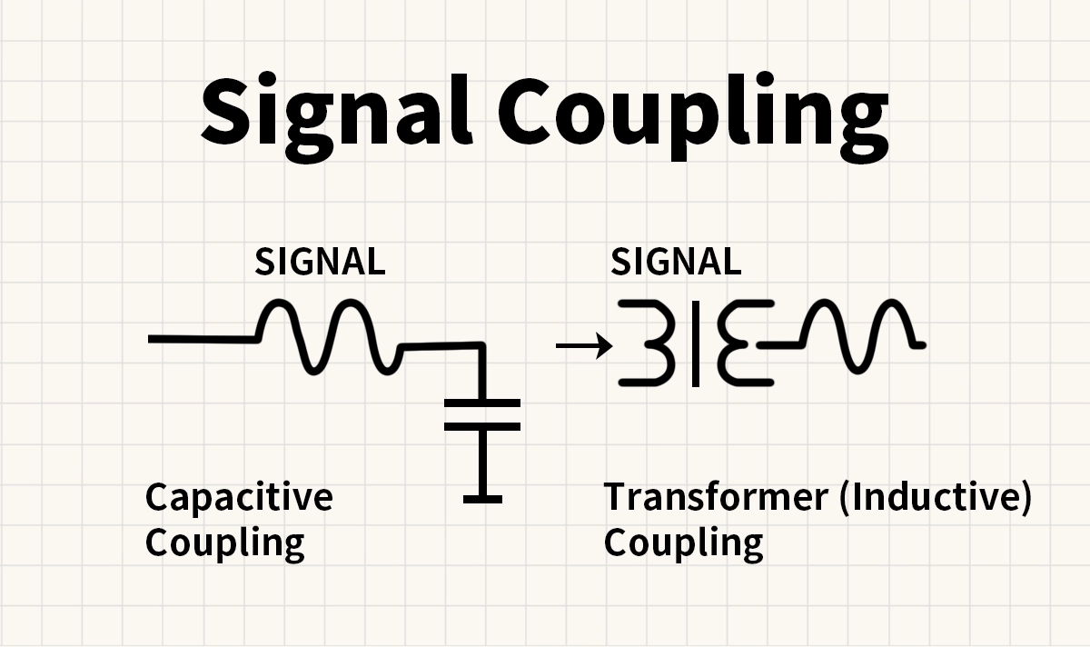
1. Capacitive Coupling
Definition: A coupling method that uses a capacitor as the medium between two circuits.
Principle: Since capacitors block DC but allow AC to pass, they enable signal transfer while removing DC bias.
Applications:
Audio amplifier input/output stages
Communication circuits for signal filtering
High-frequency PCB designs
Capacitive coupling is the most common technique because it is simple, cost-effective, and highly effective for mid- to high-frequency signals.
2. Transformer (Inductive) Coupling
Definition: A coupling method that uses a transformer or inductor to transfer signals through magnetic fields.
Principle: A transformer provides galvanic isolation between circuits while transmitting the AC signal. It also allows impedance matching, which improves efficiency in transmission lines.
Applications:
RF and telecommunication systems
Power supply isolation circuits
Transformer coupling is widely used in networking hardware, where both signal integrity and isolation are essential.
3. Direct Coupling (DC Coupling)
Definition: Directly connecting two circuits without capacitors or transformers.
Advantages: Allows both AC and DC components to pass.
Limitations: Risk of voltage mismatch or DC offset affecting downstream circuits.
Applications: Low-frequency amplifiers and digital logic circuits where DC levels must be preserved.
🔹 Signal Coupling in Electronics and Networking
Signal coupling plays a vital role in data communication, audio transmission, and PCB signal routing. In high-speed networking, for example, LAN transformers use transformer coupling to deliver Ethernet signals with 1.5kV–2kV isolation, protecting chipsets from surges, ESD, and ground potential differences.
LINK-PP, as a leading manufacturer of RJ45 connectors with integrated magnetics, provides solutions that integrate capacitive and inductive coupling principles to ensure reliable, high-speed signal transmission across industrial, automotive, and telecom applications.
🔹 Conclusion
Signal coupling is more than a theoretical concept—it is a practical engineering solution for transferring signals safely and effectively. Capacitive coupling is ideal for AC isolation, transformer coupling provides both isolation and impedance matching, and direct coupling serves special cases where DC continuity is needed.
From audio electronics to high-speed Ethernet, mastering signal coupling enables better designs, improved reliability, and enhanced system performance.


