

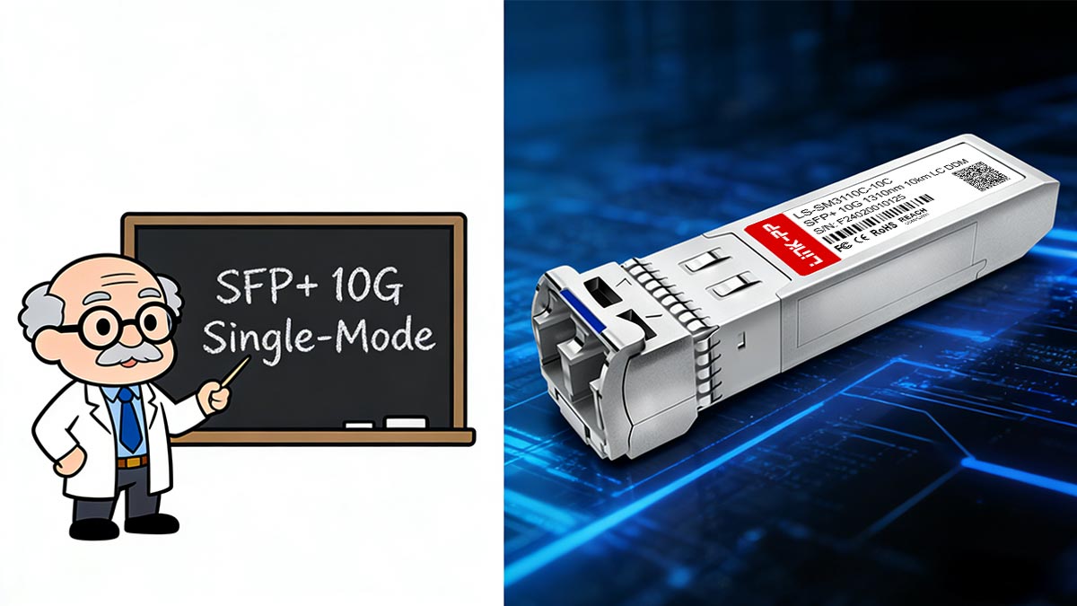
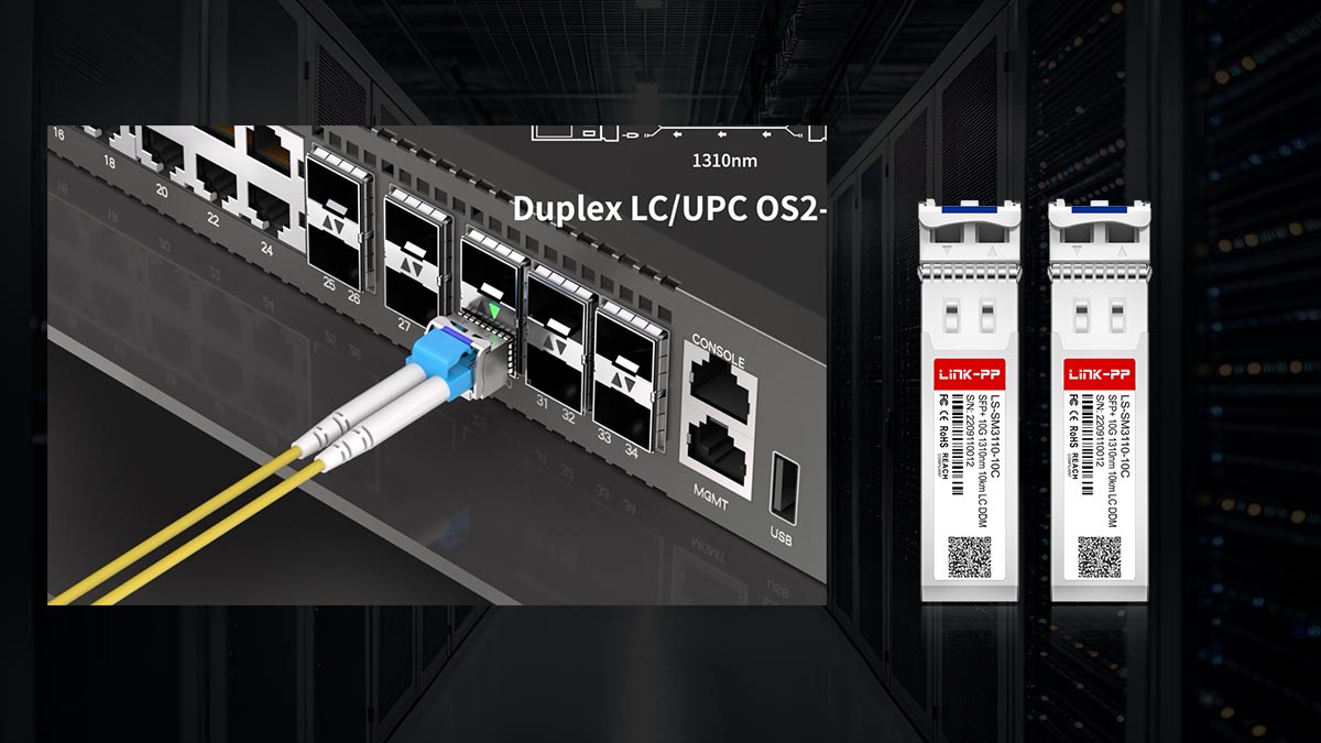
The Optical Transceiver SFP+ 10G Single-Mode Module 1310nm 10km LC is a high-performance, compact networking component designed to deliver 10 Gigabit Ethernet connectivity over single-mode fiber (SMF). These modules are widely used in data centers, enterprise networks, and telecom environments to provide reliable long-distance links with minimal signal loss and low latency.
Operating on the 1310nm wavelength and supporting distances up to 10 kilometers, SFP+ 10G single-mode modules conform to the 10GBASE-LR (Long Reach) standard defined by IEEE 802.3ae. Their LC duplex connectors make them compatible with standard single-mode patch cords while maintaining the small form-factor benefits of SFP+, including hot-pluggable operation and high port density.
By installing these optical transceivers, network engineers can upgrade existing SFP+ ports to long-distance single-mode fiber connections without replacing the switch chassis. The modules also support Digital Optical Monitoring (DOM / DDM), allowing real-time measurement of parameters such as optical output power, temperature, and voltage, ensuring operational reliability and proactive troubleshooting.
This article explores the technical features, deployment scenarios, and best practices for SFP+ 10G single-mode 1310nm LC modules, helping IT professionals make informed decisions about high-speed fiber connectivity. By the end, readers will understand how these modules integrate into modern networks, optimize long-distance connections, and maintain compatibility with various switch vendors and optical infrastructure.
1️⃣ What Is an SFP+ 10G Single-Mode Module?
An SFP+ 10G single-mode module is a hot-pluggable optical transceiver that converts electrical signals from a switch or router into optical signals suitable for single-mode fiber transmission. These modules are standardized under the Small Form-Factor Pluggable Multi-Source Agreement (SFF MSA) and the IEEE 802.3ae 10GBASE-LR specification, ensuring wide interoperability across vendors.
Single-Mode Fiber Basics
Single-mode fiber (SMF) uses a narrow core (≈9µm) to transmit light directly along the fiber axis, which minimizes modal dispersion and allows for long-distance transmission. This characteristic makes SMF the preferred medium for 10GBASE-LR applications, supporting distances up to 10 km with a single 1310nm laser source.
10GBASE-LR Standard
The 10GBASE-LR (Long Reach) standard defines the optical and electrical characteristics for 10 Gigabit Ethernet over single-mode fiber:
Data rate: 10 Gbps
Wavelength: 1310nm
Maximum distance: 10 km
Connector type: LC duplex
10GBASE-LR ensures reliable long-distance connections while maintaining backward compatibility with existing SFP+ cages in switches and routers.
Hot-Pluggable SFP+ Architecture
SFP+ modules maintain the compact footprint of SFP, allowing high port density in data-center switches. Key features include:
Hot-swappable design: Insert or remove the module without powering down the switch
Low power consumption: Typically <1W, though slightly higher than 1G SFPs due to faster SERDES operation
Standardized interface: Compatible with SFF-8431 electrical specification and LC optical interface
The SFP+ module’s internal SERDES (Serializer/Deserializer) handles high-speed serial data from the switch ASIC, encoding it for transmission through the optical laser.
1310nm Optical Wavelength and 10km Reach
The 1310nm wavelength is ideal for long-distance, single-mode fiber links because it balances low attenuation with minimal chromatic dispersion. With proper single-mode fiber installation, a 10G SFP+ 10GBASE-LR module can maintain error-free transmission up to 10 kilometers, making it suitable for:
Data center uplinks
Enterprise backbone networks
Telecom metro connections
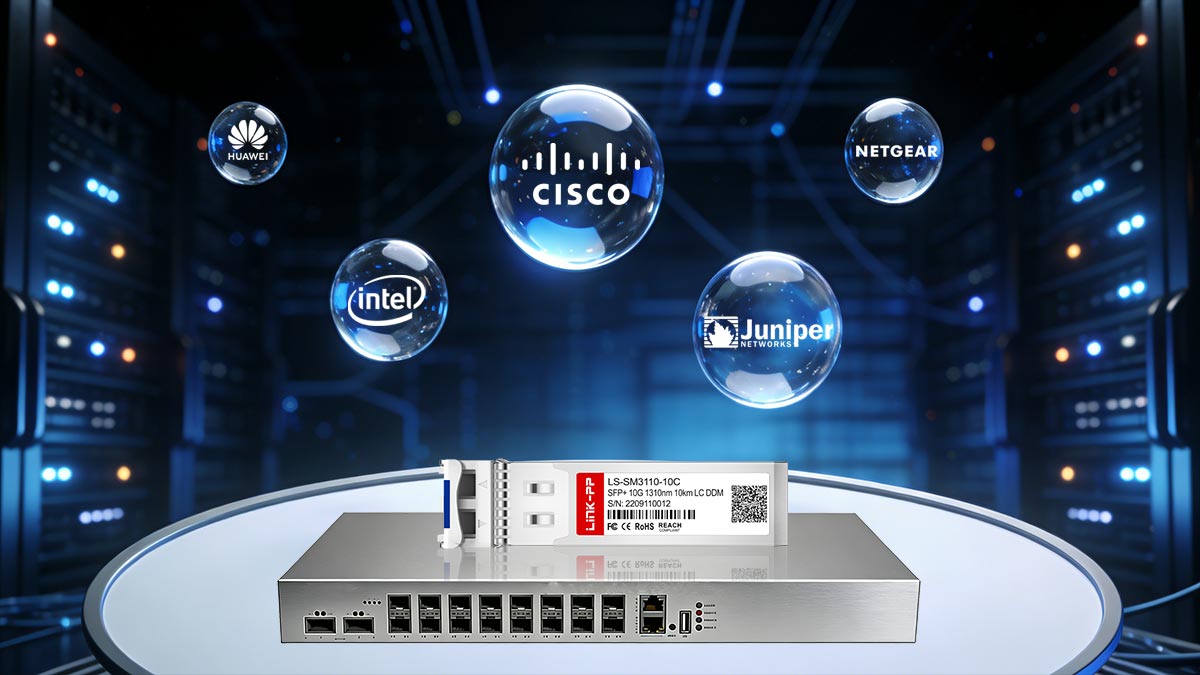
According to the IEEE 802.3ae standard and the SFF-8431 Multi-Source Agreement, these modules are vendor-independent, ensuring interoperability between switches from Cisco, Juniper, Arista, and other major manufacturers.
2️⃣ 10G SFP+ Types and Form Factors
The SFP+ 10G family of optical transceivers provides a range of options tailored for different network distances, fiber types, and deployment scenarios. Understanding the differences between 10GBASE-LR, 10GBASE-SR, and 10GBASE-ER modules is essential for selecting the right module for your infrastructure.
Common SFP+ 10G Types
10GBASE-LR (Long Reach)
Fiber type: Single-mode fiber (SMF)
Wavelength: 1310nm
Maximum distance: 10 km
Connector: LC duplex
Use case: Enterprise backbone, data center uplinks, metro networks
10GBASE-SR (Short Reach)
Fiber type: Multimode fiber (MMF)
Wavelength: 850nm
Maximum distance: 300 m (OM3) / 400 m (OM4)
Connector: LC duplex
Use case: Rack-to-rack or intra-data center connections
10GBASE-ER (Extended Reach)
Fiber type: Single-mode fiber (SMF)
Wavelength: 1550nm
Maximum distance: Up to 40 km
Connector: LC duplex
Use case: Long-haul enterprise and metro networks, carrier-grade applications
LC Duplex Interface
All modern 10G SFP+ modules use LC duplex connectors, which provide:
Compact design suitable for high-density switch panels
Reliable optical alignment for low insertion loss
Easy patching in fiber management systems
The LC interface has become the industry standard for both single-mode and multimode SFP+ modules.
Speed, Distance, and Application Comparison Table
Module Type | Fiber Type | Wavelength | Max Distance | Connector | Typical Application |
|---|---|---|---|---|---|
10GBASE-LR | SMF | 1310nm | 10 km | LC duplex | Enterprise backbone, data center uplinks, metro networks |
10GBASE-SR | MMF | 850nm | 300–400 m | LC duplex | Rack-to-rack, intra-data center links |
10GBASE-ER | SMF | 1550nm | 40 km | LC duplex | Long-haul enterprise, carrier networks |
By understanding the differences in wavelength, fiber type, and reach, network engineers can choose the optimal 10gbe SFP+ module for their infrastructure, ensuring reliable performance and compatibility with existing switches.
3️⃣ How SFP+ Modules Work Inside a Switch or Router
10G SFP+ optical transceivers are compact, high-speed modules that enable seamless integration of fiber optics into switches and routers. Understanding their internal operation is critical for network engineers seeking optimal performance, reliability, and compatibility.
SERDES Interface and Host Communication
At the heart of every SFP+ module is the SERDES (Serializer/Deserializer) interface, which converts high-speed parallel data from the host switch ASIC into serial optical signals for transmission over fiber.
Key points:
The SERDES handles 10 Gbps serial data streams, conforming to the SFF-8431 SFP+ electrical specification.
It ensures signal integrity and timing alignment between the switch and the optical module.
Engineers rely on this interface to maintain low latency and error-free transmission over long distances.
By translating parallel host data into serial signals, the SFP+ effectively acts as a miniaturized fiber interface, connecting high-speed network devices without requiring additional hardware.
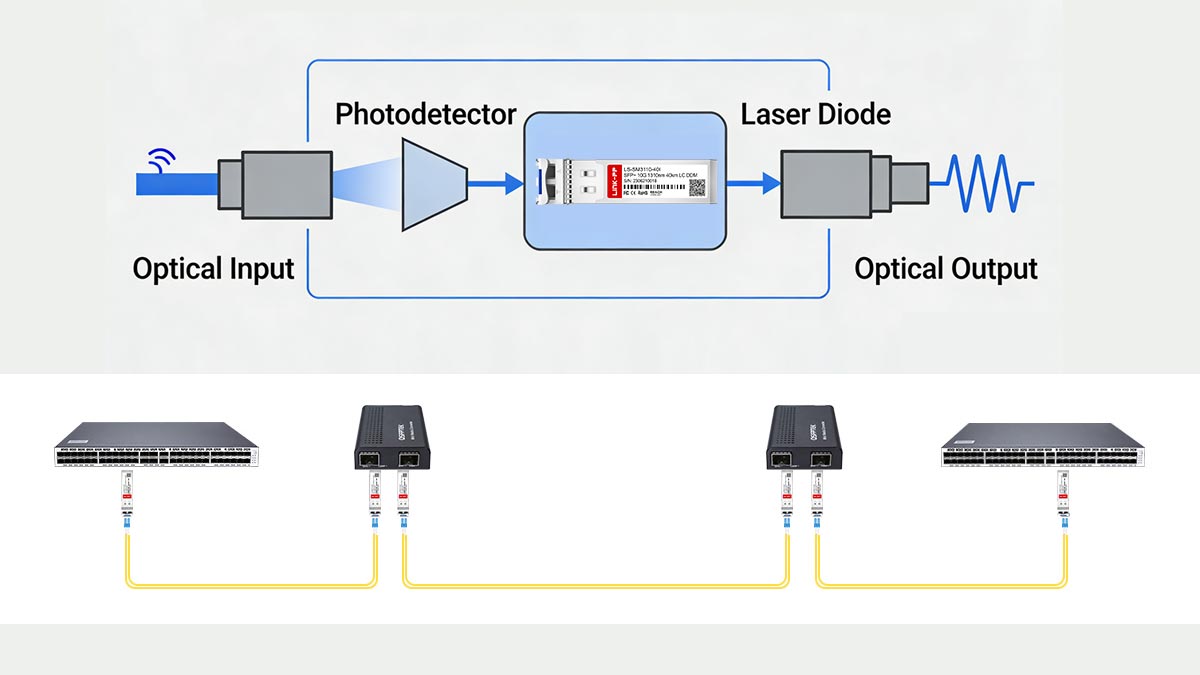
Optical Signal Conversion
Inside the module, electrical signals from the SERDES are converted into optical signals using a laser diode (for transmission) and a photodiode (for reception).
Transmission: The SERDES output drives a 1310nm laser in 10GBASE-LR modules.
Reception: Incoming optical signals are converted back into electrical signals via the photodiode.
The LC duplex interface separates transmit (TX) and receive (RX) channels, ensuring full-duplex communication.
This process allows a standard SFP+ port to act as a mini media converter, bridging electrical switch signals with optical fiber infrastructure without external devices.
Digital Diagnostics (DOM/DDM)
Modern SFP+ modules support Digital Optical Monitoring (DOM) or Digital Diagnostic Monitoring (DDM), which provides real-time telemetry, including:
Optical output and input power
Laser bias current
Module temperature
Supply voltage
DOM/DDM helps network engineers:
Monitor link health proactively
Detect signal degradation or fiber faults
Optimize network reliability and uptime
Standards such as SFF-8472 define the DOM interface, ensuring consistent access across vendors and switches.
Why Engineers Call It a “Mini Fiber Interface”
Network professionals often refer to SFP+ modules as “mini fiber interfaces” because:
They integrate all optical conversion components inside a small, hot-swappable form factor.
They replace bulky media converters, allowing direct fiber connections from SFP+ ports.
They maintain full 10G bandwidth while providing the flexibility to connect different fiber types or distances without modifying the switch chassis.
This combination of compact size, high performance, and plug-and-play convenience has made SFP+ modules the industry standard for 10 Gigabit optical networking.
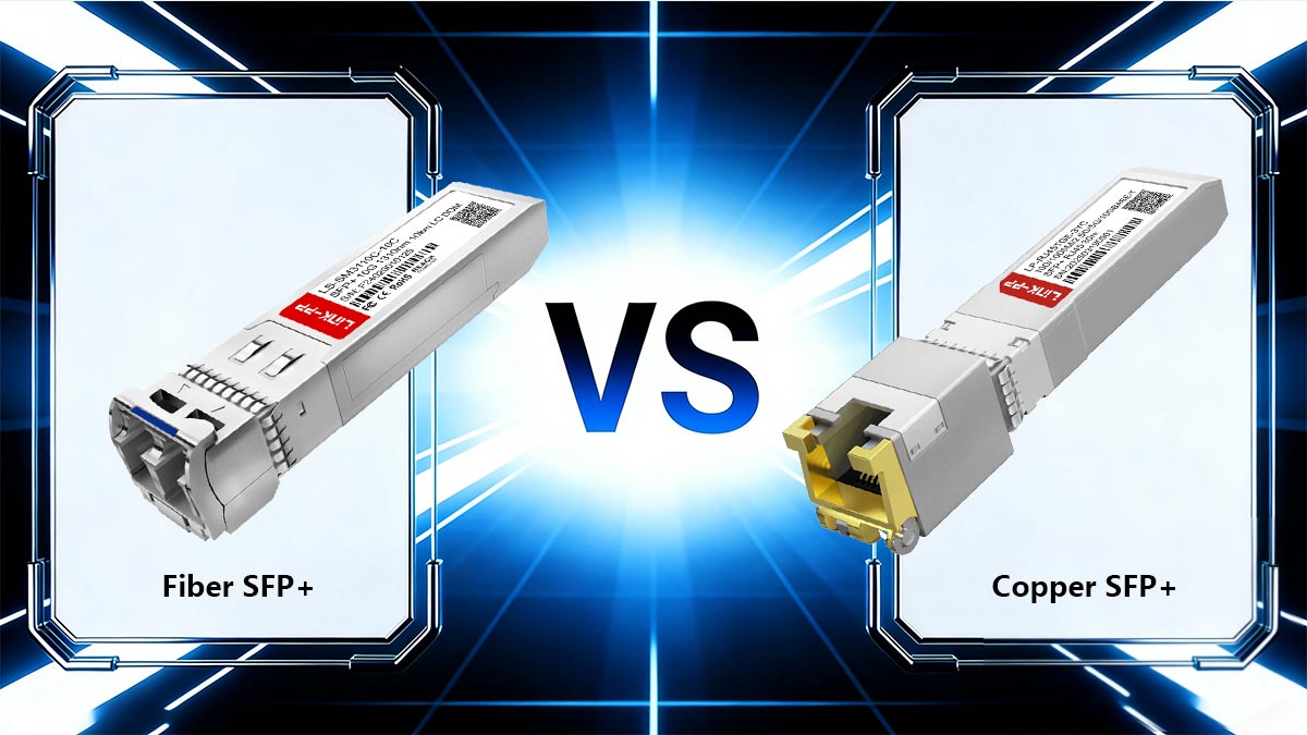
4️⃣ Optical vs. Copper SFP+: Performance, Latency, and Use Cases
When designing high-speed networks, engineers often need to choose between optical SFP+ modules and copper SFP+ (10GBASE-T) modules. Each option has distinct advantages and trade-offs regarding performance, distance, power, and electromagnetic interference (EMI). Understanding these differences ensures reliable, high-speed connectivity in enterprise and data-center environments.
Performance and Latency
Optical SFP+ modules provide low-latency transmission because the signal is transmitted as light over fiber, bypassing the electrical encoding and decoding required in copper modules. By contrast, copper 10GBASE-T modules integrate a PHY chip and SERDES, which introduces a slight delay due to electrical-to-optical conversion internally and auto-negotiation circuitry.
Reddit discussions from networking professionals highlight that copper SFP+ behaves like a mini media converter, with latency typically <1µs per module, whereas optical SFP+ links exhibit sub-microsecond latency, making them preferable for high-frequency trading, core data-center uplinks, and latency-sensitive applications.
Power Consumption
Feature | Optical SFP+ | Copper SFP+ (10GBASE-T) |
|---|---|---|
Typical Power | 1 W or less | 1–2.5 W |
Heat Generation | Low | Higher (PHY and signal processing) |
Cooling Requirement | Minimal | Requires adequate airflow, especially in high-density switches |
Optical SFP+ modules are more energy-efficient, especially in high-density 10G switch deployments, while copper modules can increase switch thermal load.
Distance and Medium
Feature | Optical SFP+ 10G | Copper SFP+ 10GBASE-T |
|---|---|---|
Medium | Single-mode or multi-mode fiber | Cat5e / Cat6 copper twisted-pair |
Max Distance | 10 km (SMF, 10GBASE-LR) | 100 m |
EMI Immunity | Immune | Sensitive to electromagnetic interference |
Optical modules excel in long-distance or EMI-prone environments, such as data centers with dense cabling or metro links, while copper modules are suitable for short-distance connections and legacy RJ45 infrastructure.
Use Cases
Fiber SFP+ 10G Modules:
Data center uplinks between switches
Metro and campus backbone connections
Environments with high EMI or long-distance requirements
Copper SFP+ 10G Modules:
Adding extra RJ45 ports to switches
Short-distance connections in enterprise access networks
Lab or temporary deployments where fiber is unavailable
Key Takeaways from Community Insights
Engineers on Reddit and networking forums emphasize that optical SFP+ modules provide predictable low-latency performance, critical for mission-critical infrastructure.
10G Copper module is convenient for retrofitting legacy networks but can consume more power and introduce slight latency due to internal PHY and signal processing.
The choice often depends on distance, EMI environment, switch power budget, and budget constraints.
Summary Comparison Table
Feature | Optical SFP+ | Copper SFP+ 10GBASE-T |
|---|---|---|
Medium | SMF / MMF | Cat5e / Cat6 |
Max Distance | 10 km (SMF) | 100 m |
Latency | Very low | Slightly higher |
Power | Low | Higher (1–2.5 W) |
EMI Sensitivity | Immune | Susceptible |
Deployment | Data center uplinks, metro | Short enterprise links, lab |
By understanding these differences, network engineers can select the optimal module for their performance requirements, physical infrastructure, and cost considerations, ensuring both network reliability and efficiency.
5️⃣ Choosing the Right SFP+ 10G Single-Mode 1310nm 10km LC Module
Selecting the right 10G SFP+ single-mode module is critical to ensure stable, high-performance, and long-distance network connectivity. Engineers must consider fiber type, connector standards, transmission distance, and switch compatibility before deploying these modules in enterprise or data-center networks.
Cable Type: Single-Mode Fiber
Single-mode fiber (SMF) is mandatory for 10GBASE-LR SFP+ modules:
Core diameter: ≈9 µm
Wavelength: 1310nm for standard LR modules
Purpose: Minimizes modal dispersion for long-distance transmission up to 10 km
Using multimode fiber with a 10GBASE-LR module can result in high insertion loss, signal distortion, or complete link failure. Always verify that the patch cords and fiber infrastructure match the single-mode specification.
Connector Type: LC Duplex
LC duplex connectors are the industry standard for SFP+ modules:
Compact footprint suitable for high-density switches
Separate TX and RX channels for full-duplex operation
Reliable optical alignment reduces insertion loss and signal degradation
When purchasing modules, ensure that the LC connectors match the existing fiber infrastructure, or use LC-to-LC patch cords for compatibility.
Distance and Dispersion Considerations
Although 10GBASE-LR module is rated for up to 10 km, real-world deployment requires attention to:
Fiber attenuation: SMF typically has ~0.35 dB/km at 1310nm
Connector and splice loss: Each connection can add 0.3–0.5 dB loss
Chromatic dispersion: Minimal at 1310nm but can impact very long links
Planning for link budget and distance margin ensures that the module maintains error-free 10G performance.
Switch Compatibility and Firmware Verification
Compatibility between SFP+ modules and switch vendors is essential:
EEPROM verification: The module’s EEPROM must match the switch’s expected vendor ID and capabilities
Firmware restrictions: Some switches may block unverified third-party modules
Port power budget: SFP+ modules consume ~1W, and dense switch deployments require adequate power and cooling
Best practices:
Check the vendor compatibility matrix before purchasing
Test modules in a lab environment prior to production deployment
Update switch firmware to ensure support for third-party SFP+ modules if needed
By carefully selecting a single-mode fiber SFP+ module with proper LC connectors, distance planning, and switch compatibility verification, engineers can ensure long-distance 10G connectivity with minimal errors, optimized for both performance and network reliability.
6️⃣ Third-Party SFP+ Compatibility and Vendor Lock-In
One of the most common concerns when deploying 10G SFP+ optical modules is whether third-party (compatible) transceivers will work reliably with branded switches such as those from Cisco Systems, Juniper Networks, Arista Networks, or Hewlett Packard Enterprise.
Many network vendors implement vendor identification mechanisms in their switches to encourage the use of OEM optics, a practice often described as vendor lock-in. However, modern compatible SFP+ modules are widely used in enterprise and data-center environments when proper verification steps are followed.
This section explains how compatibility works, how EEPROM coding affects module recognition, and how to safely deploy third-party optics.
OEM vs. Compatible SFP+ Modules
Factor | OEM Optical Modules | Compatible / Third-Party Modules |
|---|---|---|
Manufacturer | Switch vendor branded | Independent optics manufacturers |
Price | Higher | Typically 50–80% lower |
Compatibility | Guaranteed with vendor hardware | Requires vendor coding |
Availability | Limited to vendor supply | Broad multi-vendor availability |
Performance | Standardized | Usually identical if built to spec |
Technically, both OEM and third-party modules follow the same optical and electrical specifications defined by standards such as 10GBASE-LR in the IEEE Ethernet standards.
In most cases, the hardware components (laser, driver IC, receiver) are manufactured by the same optical component suppliers used by OEM vendors.
The Role of EEPROM Coding in SFP+ Modules
Every SFP+ module contains a small memory chip called EEPROM (Electrically Erasable Programmable Read-Only Memory).
The EEPROM stores identification data such as:
Vendor name
Part number
Supported standards
Wavelength and reach
Diagnostic capability (DOM/DDM)
When a module is inserted, the switch reads this EEPROM data through the I²C interface defined in the SFP Multi-Source Agreement.
If the switch firmware expects a specific vendor ID, it may display warnings or block unsupported optics.
Typical behavior includes:
Switch Behavior | Result |
|---|---|
Allow but warn | Module works but shows compatibility warning |
Soft restriction | Requires command to allow unsupported modules |
Hard restriction | Module disabled |
Firmware Restrictions and Vendor Lock-In
Some network vendors implement firmware checks designed to restrict third-party optics.
Common mechanisms include:
Vendor name verification
Optical power calibration checks
EEPROM signature validation
For example, networking forums often mention commands that enable unsupported optics in some switches, such as:
service unsupported-transceiveror
allow-unsupported-transceiverHowever, availability of these commands depends on the specific switch platform and firmware version.
Are Third-Party SFP+ Modules Reliable?
In practice, high-quality compatible SFP+ modules are widely used in production networks, including:
enterprise campus networks
hyperscale data centers
telecom infrastructure
lab and test environments
Reliability depends primarily on:
compliance with IEEE Ethernet standards
quality of the laser and receiver components
accurate EEPROM coding
proper thermal design
Reputable optical manufacturers also perform multi-vendor compatibility testing before releasing modules.
Best Practices for Verifying Compatibility
To safely deploy third-party SFP+ modules, network engineers should follow several verification steps.
1. Check the switch compatibility matrix
Most optics vendors provide a vendor compatibility list mapping modules to supported switches.
2. Verify EEPROM coding
Ensure the module is coded for the specific platform (for example Cisco-compatible, Juniper-compatible, etc.).
3. Confirm Digital Diagnostics (DOM/DDM)
Diagnostic monitoring ensures the module can report:
optical transmit power
receive power
module temperature
supply voltage
These readings are essential for troubleshooting.
4. Test modules before large-scale deployment
Lab testing verifies:
link establishment
stability under traffic load
compatibility with switch firmware
Vendor lock-in mechanisms mainly rely on EEPROM identification and firmware validation, not fundamental hardware differences.
When sourced from reliable manufacturers and properly coded, compatible SFP+ optical modules can deliver the same performance and reliability as OEM optics, often at significantly lower cost.
For network operators, the best strategy is to combine:
verified compatibility coding
standards-compliant optics
proper lab validation
This approach ensures stable 10G fiber connectivity without unnecessary vendor restrictions.
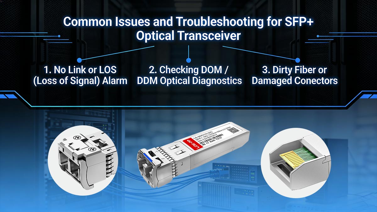
7️⃣ Common Issues and Troubleshooting for SFP+ Optical Transceiver
Even though 10G SFP+ optical transceivers are highly reliable, network engineers may occasionally encounter link failures, optical alarms, or unstable connections. Most issues can be quickly resolved by following a systematic troubleshooting process focused on optics, fiber cleanliness, and module diagnostics.
Modern SFP+ modules support Digital Optical Monitoring (DOM/DDM) defined in the SFF‑8472 Digital Diagnostic Monitoring Interface for Optical Transceivers, which allows engineers to check real-time optical parameters directly from the switch or router.
Below are the most common problems and practical troubleshooting steps.
1. No Link or LOS (Loss of Signal) Alarm
A LOS alarm indicates that the receiver cannot detect sufficient incoming optical power. This is one of the most frequent issues when deploying 10G-LR SFP+ modules.
Common causes
TX and RX fibers reversed
Fiber not fully inserted into the LC port
Fiber type mismatch (MMF vs. SMF)
Optical loss exceeding the link budget
Incompatible or unsupported module
Troubleshooting steps
Verify the TX/RX polarity of the LC duplex cable.
Confirm the fiber type is single-mode (SMF) for 10GBASE-LR.
Reseat the SFP+ module and check the link LED status.
Test with a known-good fiber patch cable.
Check switch logs for transceiver compatibility warnings.
2. Checking DOM / DDM Optical Diagnostics
Most enterprise switches allow engineers to read real-time optical data from SFP+ modules.
Typical command examples:
show interfaces transceiver detailsor
show interfaces diagnostics opticsDOM/DDM parameters typically include:
Parameter | Description |
|---|---|
TX Optical Power | Output power of the laser |
RX Optical Power | Received optical signal level |
Module Temperature | Internal temperature of the transceiver |
Supply Voltage | Operating voltage |
Laser Bias Current | Current driving the laser diode |
Normal operating ranges help engineers identify problems such as:
fiber attenuation
optical misalignment
module overheating
3. Dirty Fiber or Damaged Connectors
One of the most overlooked causes of optical network problems is contamination on fiber connectors.
Even microscopic dust particles can cause:
insertion loss
signal reflection
unstable links
This is particularly critical for LC connectors used in SFP+ modules.
Best practices
Always inspect connectors with a fiber inspection microscope
Clean connectors using lint-free wipes or fiber cleaning pens
Avoid touching fiber end faces
Always install dust caps when ports are unused
Industry guidelines from organizations such as the Fiber Optic Association emphasize the rule:
“Inspect before you connect.”
4. Step-by-Step Troubleshooting Workflow
The following checklist helps quickly isolate most 10G optical link problems:
Step 1 — Check module status
Confirm the switch detects the SFP+ module
Verify compatibility messages in system logs
Step 2 — Verify fiber connections
Ensure correct TX/RX orientation
Confirm the cable is LC duplex single-mode fiber
Step 3 — Inspect and clean connectors
Clean both fiber ends and the SFP+ interface
Step 4 — Check optical diagnostics
Compare RX power against module specifications
Step 5 — Swap components
Replace fiber cable
Replace SFP+ module
Test with another switch port
Quick Troubleshooting Summary
Issue | Likely Cause | Fix |
|---|---|---|
No link | TX/RX reversed | Swap fiber polarity |
LOS alarm | Low RX optical power | Check fiber and connectors |
Intermittent link | Dirty connectors | Clean fiber endfaces |
Module overheating | Poor airflow | Improve switch cooling |
Compatibility warning | Vendor lock | Use correctly coded module |
8️⃣ FAQs About SFP+ 10G Single-Mode 1310nm LC Modules
Q1. What is a 10G SFP+ single-mode transceiver?
A 10G SFP+ single-mode transceiver is a hot-pluggable optical module that enables 10 Gigabit Ethernet communication over single-mode fiber (SMF).
These modules typically follow the 10GBASE-LR Ethernet standard defined in IEEE 802.3ae, operating at a 1310 nm wavelength and supporting transmission distances up to 10 km using LC duplex fiber connectors.
They are widely used in:
data center switch uplinks
enterprise backbone networks
metro aggregation networks
Q2. What distance can 10GBASE-LR reach?
A 10GBASE-LR SFP+ module can typically transmit up to 10 km (6.2 miles) over single-mode fiber at 1310 nm.
The actual achievable distance depends on:
fiber attenuation
connector and splice losses
link budget margin
In properly designed networks, 10GBASE-LR provides stable long-distance connectivity for campus and enterprise backbone links.
Q3. Can SFP+ 10G work with multi-mode fiber?
Most 10G SFP+ single-mode modules (LR) are designed specifically for single-mode fiber and should not be used with multi-mode fiber.
Using LR optics on multimode fiber can lead to:
excessive optical loss
modal dispersion
unstable links
For multimode fiber deployments, 10GBASE-SR SFP+ modules operating at 850 nm are the correct choice.
Q4. Why is DOM (Digital Optical Monitoring) important?
Digital Optical Monitoring (DOM)—also known as DDM—allows switches and routers to read real-time diagnostics from SFP+ modules.
According to the SFF-8472 Digital Diagnostic Monitoring Interface specification, DOM provides key parameters such as:
transmit optical power (TX)
receive optical power (RX)
module temperature
supply voltage
laser bias current
These diagnostics help engineers:
monitor optical link health
detect fiber degradation early
troubleshoot network issues quickly
Q5. Are third-party SFP+ modules reliable?
Yes. High-quality third-party compatible SFP+ modules can deliver the same performance as OEM optics when they comply with industry standards and vendor compatibility requirements.
Reliable compatible optics typically include:
correct EEPROM vendor coding
compliance with IEEE Ethernet standards
multi-vendor interoperability testing
Many enterprises and data centers deploy compatible optics to reduce network costs while maintaining performance and reliability.
9️⃣ Conclusion: When to Deploy 10G SFP+ Single-Mode Modules in Modern Networks
10G SFP+ single-mode 1310nm 10 km modules remain one of the most widely deployed solutions for high-speed fiber connectivity in modern networks.
They are particularly suitable for:
data center switch uplinks
enterprise backbone networks
campus and metro fiber links
long-distance connections up to 10 km
By leveraging single-mode fiber infrastructure, these modules deliver low latency, high reliability, and stable 10 Gbps throughput across extended distances.
However, they may not be the best choice for:
short-range multimode deployments
environments where lower-cost 10GBASE-SR solutions are sufficient
Explore Compatible 10G SFP+ Modules
For organizations deploying reliable and cost-effective optical networking solutions, compatible transceivers provide a practical alternative to OEM optics.
You can explore:
compatible 10G SFP+ single-mode modules
detailed datasheet downloads
switch compatibility guidance
technical support for deployment
through the LINK-PP Official Store and engineering support resources.


