🔹 What is a Common-Mode Choke (CMC)?
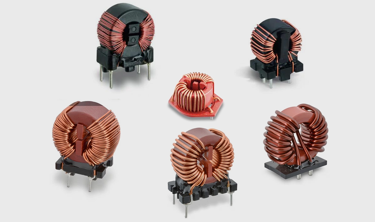
A common-mode choke (CMC) is a passive magnetic component consisting of two (or more) windings on a shared core. It presents high impedance to common-mode currents (noise present equally on both lines) while presenting low impedance to differential (intended) signals. Hence, the desired data passes with minimal attenuation while unwanted common-mode interference is suppressed.
🔹 How a CMC works
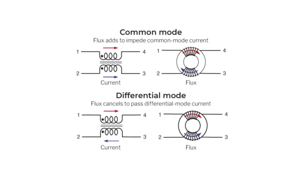
Magnetic cancellation and addition: differential currents flow in opposite directions in the paired windings; their magnetic fields cancel in the core, so the choke looks like a near-zero inductance to the differential signal. For common-mode currents, the fields add, producing inductance that blocks or attenuates the unwanted noise. This selective behavior is what makes CMCs ideal for high-speed balanced lines such as Ethernet.
Differential vs common-mode
Differential (useful signal): passes with little loss.
Common-mode (noise): sees high impedance → attenuated or reflected.
🔹 Why CMCs matter in Ethernet
EMI/EMC compliance: CMCs reduce cable-borne emissions and enhance immunity to external noise sources, enabling devices to pass regulatory tests.
Signal integrity: Properly specified CMCs maintain differential insertion loss and preserve eye diagrams across the target data rate (10/100/1000/2.5G/5G, etc.)
PoE considerations: DC from PoE biases the choke core; designers must choose cores and windings with adequate saturation margin so CMC performance is retained under PoE load.
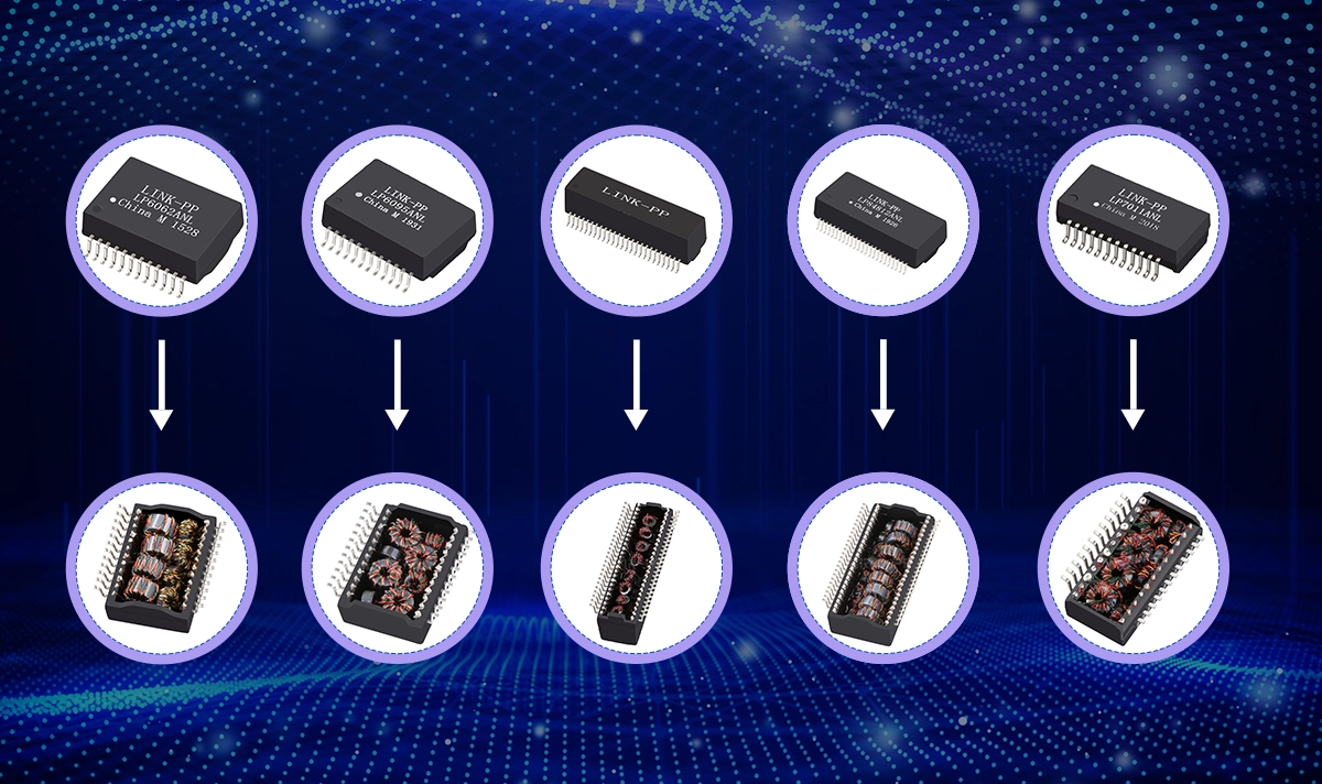
Integration with LAN transformers: Many RJ45 Magnetic Jacks integrate CMC functionality or pair a dedicated CMC with the isolation transformer to meet port-level EMC and isolation requirements.
🔹 Key parameters to evaluate when selecting a CMC
Impedance vs frequency (common-mode impedance): indicates how effectively the choke attenuates noise across the problematic frequency band.
Insertion loss / differential impedance: must be small within the Ethernet frequency band to avoid degrading the data signal.
DC rating & saturation current: for PoE and long-run applications, choose a choke whose core won’t saturate under expected DC bias.
DC resistance (DCR): low DCR reduces voltage drop and power loss, important for power-carrying applications.
Package & mounting (SMD vs through-hole), thermal ratings, and automotive qualifications (e.g., AEC-Q): choose based on environment and volume requirements.
🔹 Practical design & layout tips
Place magnetics near the RJ45 cable entry: minimizes loop area and reduces board-level radiation.
Follow PHY vendor guidance: some PHYs / reference designs specify choke placement (device side vs cable side) and recommended magnetics topology. Check PHY application notes when available.
Balance filtering vs bandwidth: excessive common-mode inductance or added capacitance can move the filter cutoff and impact high-speed signalling; use vendor filter design guides and test prototypes.
🔹 Conclusion
A Common-Mode Choke (CMC) is a precision EMI filter that suppresses unwanted common-mode noise while allowing differential signals to pass — making it indispensable in Ethernet magnetics and LAN filters. For reliable Ethernet and PoE performance, CMCs should be specified by key parameters such as impedance, insertion loss, and DC saturation current, and validated against PHY vendor guidelines and EMC test results. CMCs play a central role in LINK-PP’s LAN transformers: aligning transformer isolation with choke impedance and saturation behavior ensures both compliance with EMI standards and stable system operation.