

Frame Check Sequence (FCS) is a Layer 2 error-detection mechanism used in Ethernet and other data communication protocols to verify whether a network frame has been corrupted during transmission. In modern Ethernet networks, the FCS field is typically based on CRC-32 and is appended to the end of every Ethernet frame to help switches, routers, servers, and network interface cards (NICs) detect transmission errors before the data is processed by upper-layer protocols.
In practical networking environments, FCS errors are not just theoretical protocol events. They are often early warning signs of real physical-layer problems, including damaged Ethernet cables, dirty fiber connectors, unstable optical modules, electromagnetic interference (EMI), duplex mismatches, or degraded signal integrity on high-speed links. In data centers and enterprise networks, repeated CRC/FCS errors are commonly associated with faulty SFP, SFP+, QSFP, or QSFP28 optical transceivers and poor-quality cabling infrastructure.
As Ethernet speeds continue to evolve from 1G and 10G to 100G, 400G, and even 800G Ethernet defined under standards such as IEEE 802.3ck, maintaining frame integrity has become increasingly critical. Even a very small Bit Error Rate (BER) can lead to packet corruption, retransmissions, increased latency, and application instability. This is why network engineers frequently monitor FCS counters on switches and network devices when troubleshooting packet loss or intermittent connectivity issues.
This article explains what Frame Check Sequence (FCS) means, how CRC-32 works inside Ethernet frames, why FCS errors occur, how they relate to optical modules and fiber links, and how network professionals diagnose and resolve CRC/FCS-related problems in real-world deployments. By the end of this guide, you will understand both the theoretical foundation and the operational significance of FCS in modern Ethernet networks.
✅ What Is Frame Check Sequence (FCS)?
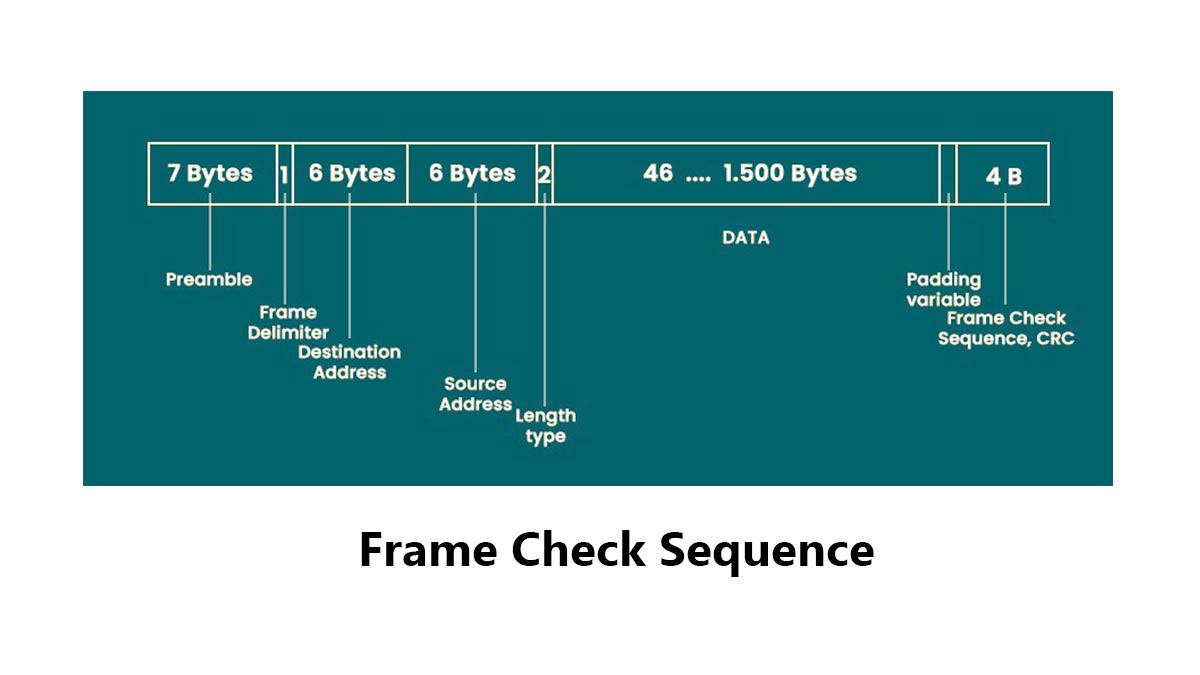
Frame Check Sequence (FCS) is the trailer field at the end of an Ethernet frame that carries a CRC value used to detect transmission errors. In IEEE 802.3 framing, the FCS is 4 bytes long and helps receivers decide whether a frame is intact or corrupted before the data is accepted.
FCS Micro Definition
FCS (Frame Check Sequence) is a Layer 2 trailer field used to verify Ethernet frame integrity during transmission.
Simple definition: FCS = The error-checking value attached to the end of an Ethernet frame
Simplified Ethernet frame structure:
| Ethernet Header | Payload | FCS |If the received FCS does not match the recalculated value, the frame is dropped.
CRC-32 Micro Definition
CRC-32 (Cyclic Redundancy Check 32-bit) is the mathematical algorithm used to generate the Ethernet FCS value.
In Ethernet:
CRC-32CRC\text{-}32CRC-32
Basic process:
Frame Data → CRC-32 Calculation → FCSReceiving side:
Received Frame → Recalculate CRC → Compare with FCSCRC-32 is highly effective at detecting:
Bit errors
Burst errors
Signal corruption
Transmission noise
Why FCS Is Placed at the End of the Frame
FCS is placed at the end of the Ethernet frame because the CRC calculation must be completed after the entire frame data is processed.
Process flow:
Frame Generated → CRC Calculated → FCS AppendedThis design allows Ethernet devices to verify the integrity of the complete frame before accepting the data.
In real networks, repeated FCS errors usually indicate physical-layer problems, including:
Common Cause | Typical Result |
|---|---|
Damaged Ethernet cable | CRC/FCS errors |
Dirty fiber connector | Packet corruption |
Faulty SFP/QSFP optical module | Intermittent packet loss |
EMI interference | Random frame corruption |
Because of this, FCS errors are widely used by network engineers as an early indicator of link-quality or optical transceiver problems.
✅ How Does FCS Work in Ethernet Frames?
When a sender transmits an Ethernet frame, it calculates a CRC over the frame contents and writes that result into the FCS field. The receiver performs the same calculation and compares the value. If the values match, the frame is accepted; if they do not, the frame is discarded. That is why FCS is a fast Layer 2 integrity check.
FCS verification happens entirely at Layer 2 and is usually processed by Ethernet hardware such as NICs, switch ASICs, and optical interfaces. This allows corrupted frames to be detected at wire speed before they affect higher-layer protocols or applications.
Sender-Side CRC Generation
Before transmitting an Ethernet frame, the sender calculates a CRC-32 value from the frame data.
Basic process:
Ethernet Frame Data → CRC-32 Calculation → FCS GeneratedThe generated CRC value is then appended to the end of the frame as the FCS field.
This Simplified Ethernet frame process helps ensure that the transmitted frame can later be verified for integrity by the receiving device.
Receiver-Side Verification
When the frame arrives, the receiving device recalculates the CRC-32 value using the received frame contents.
Verification process:
Received Frame → Recalculate CRC → Compare with FCSTwo possible outcomes:
Result | Action |
|---|---|
CRC matches FCS | Frame accepted |
CRC does not match FCS | Frame rejected |
This mechanism allows Ethernet devices to quickly detect corrupted packets caused by transmission errors, signal noise, or physical-layer issues.
Frame Discard Behavior
If the recalculated CRC value does not match the received FCS, the Ethernet frame is automatically discarded.
Typical causes of corrupted frames include:
Damaged Ethernet cables
Dirty fiber connectors
Faulty SFP/QSFP optical modules
Signal integrity problems on high-speed links
For example:
Original Data → 10101010
Corrupted Data → 10101110
Even a single-bit change can cause the CRC verification to fail.
In enterprise networks and data centers, increasing CRC/FCS counters on switches often indicate lower-layer transmission problems, especially on fiber links and optical transceiver connections.
✅ FCS vs. CRC vs. TCP Checksum: What Is the Difference?
CRC is the algorithm; FCS is the field that stores the CRC result inside the Ethernet frame. TCP checksum is different: it works at Layer 4 and protects the TCP segment, while FCS protects the Layer 2 frame. Because these checks happen at different layers, they solve different reliability problems and should not be treated as interchangeable.
What Is CRC?
CRC (Cyclic Redundancy Check) is the mathematical algorithm used to detect transmission errors.
In Ethernet: CRC-32
CRC analyzes the binary contents of the Ethernet frame and generates a unique verification value.
Basic process:
Frame Data → CRC Calculation → Result Stored in FCSCRC itself is not a visible frame field. It is simply the calculation method used to generate the FCS value.
What Is FCS?
FCS (Frame Check Sequence) is the actual 4-byte field located at the end of the Ethernet frame.
Simplified structure:
| Ethernet Header | Payload | FCS |The FCS contains the CRC result calculated by the sender. The receiving device recalculates the CRC and compares it with the received FCS value to verify frame integrity.
If the values do not match:
Frame RejectedThis process helps Ethernet devices quickly detect corrupted frames caused by cable faults, optical module instability, signal noise, or transmission errors.
What Is TCP Checksum?
TCP checksum is a Layer 4 integrity-checking mechanism used by the TCP protocol.
Unlike FCS, which protects only a single Ethernet frame on a local link, TCP checksum protects the TCP segment across the entire end-to-end communication path.
TCP checksum verifies:
TCP header
Payload data
Pseudo-header information
Simplified process:
TCP Segment → Checksum Calculation → Verification at ReceiverEven if an Ethernet frame passes the FCS check successfully, TCP checksum verification can still fail later if corruption occurs elsewhere in the network stack.
Key Differences Between FCS, CRC, and TCP Checksum
Item | OSI Layer | Protects | Where It Exists |
|---|---|---|---|
FCS | Layer 2 | Ethernet frame | End of Ethernet frame |
CRC | Layer 2 concept | Error-detection calculation | Computed and stored in FCS |
TCP Checksum | Layer 4 | TCP segment | TCP header |
✅ Why Do FCS Errors Happen on Switches, NICs, Fiber Links, and Optical Modules?
FCS errors usually mean the frame arrived corrupted somewhere along the path. In real networks, the root cause is often physical-layer or link-quality related: bad cables, dirty fiber connectors, incompatible optics, incorrect inter-frame gap behavior, or a failing optical module. Cisco documents that CRC/FCS errors can appear as input errors or packet loss on connected devices and that the issue often sits on the link path, not in upper-layer protocols.
Copper Cable Issues
Damaged or low-quality Ethernet cables are one of the most common causes of FCS errors.
Typical problems include:
Broken cable pairs
Poor shielding
Excessive cable bending
Incorrect cable category
Loose RJ45 connections
For example, a degraded Cat5e cable running 10GBASE-T traffic may introduce bit errors that corrupt Ethernet frames during transmission.
Fiber Contamination
Dirty or damaged fiber connectors are a major source of CRC/FCS errors in data centers.
Even microscopic dust particles on LC or MPO connectors can cause:
Optical signal attenuation
Reflection loss
Increased Bit Error Rate (BER)
Packet corruption
Common contamination sources include:
Dust on LC connectors
Scratched ferrules
Improper cleaning procedures
Contaminated MPO trunks
Optical Module Compatibility
Incompatible or unstable optical modules frequently cause FCS and CRC errors on enterprise switches and servers.
Affected optics may include:
QSFP/QSFP28 optical modules
Common causes include:
Vendor compatibility issues
Incorrect EEPROM parameters
Unstable laser output
Poor DSP tuning
Non-certified transceivers
Example scenarios:
Optical Issue | Typical Effect |
|---|---|
Incompatible SFP+ module | Intermittent CRC errors |
Failing QSFP28 optic | Packet corruption |
Poor-quality DAC cable | Signal integrity loss |
Overheated optical module | Random frame drops |
In many real deployments, replacing the optical transceiver immediately resolves persistent FCS problems.
Temperature and Aging
Optical modules and NICs can become unstable as temperature increases or components age over time.
Common aging-related issues include:
Laser power degradation
Thermal drift
Increased BER
Unstable clock recovery
Typical behavior:
Condition | Common Symptom |
|---|---|
High switch temperature | CRC spikes |
Aging SFP module | Intermittent packet loss |
Long uptime | Increasing interface errors |
High traffic load | Link instability |
This is why data center operators often monitor DOM/DDM values such as:
Tx power
Rx power
Module temperature
Bias current
to identify failing optics before complete link failure occurs.
Interpacket Gap and Timing Behavior
FCS errors can also occur when Ethernet timing behavior becomes unstable.
Modern Ethernet links rely on precise timing between frames, including proper Interpacket Gap (IPG) behavior. If frames are transmitted too closely together or timing synchronization becomes unstable, receivers may incorrectly process frame boundaries.
Potential causes include:
Faulty NIC firmware
PHY timing instability
Switch ASIC issues
Signal jitter on high-speed links
Simplified process:
Timing Instability
→ Frame Misalignment
→ CRC Verification Failure
→ FCS Error
Although timing-related FCS issues are less common than cable or optical problems, they become more important in high-speed Ethernet environments such as:
100G Ethernet
400G Ethernet
AI cluster networks
Hyperscale data centers
In these environments, even very small timing or signal-integrity problems can rapidly increase CRC/FCS counters across switch interfaces.
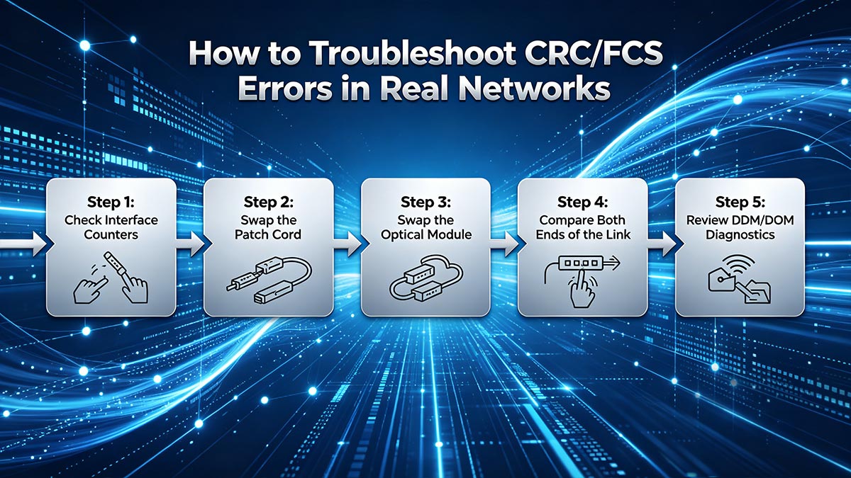
✅ How to Troubleshoot CRC/FCS Errors in Real Networks
The most effective way to troubleshoot CRC/FCS errors is to isolate the physical link step by step. In real-world Ethernet networks, corrupted frames are usually caused by cables, fiber links, optical modules, or signal-quality issues rather than higher-layer protocols. Network engineers typically follow a simple “check, replace, and compare” workflow: inspect the cable or fiber path, clean connectors, swap SFP/QSFP optics, compare interface counters on both ends, and review DOM/DDM diagnostic values to identify unstable links.
Persistent CRC/FCS errors should never be ignored, especially on 10G, 25G, 100G, or 400G Ethernet links, where even a small increase in Bit Error Rate (BER) can lead to packet loss and retransmissions.
Step 1: Check Interface Counters
Start by checking Ethernet interface statistics on switches, routers, or servers.
Common commands: show interface
or on Linux: ethtool -S eth0
Look for counters such as:
CRC errors
FCS errors
Input errors
Alignment errors
Packet drops
Typical interpretation:
Counter Behavior | Possible Cause |
|---|---|
CRC increasing slowly | Minor signal issue |
Rapidly increasing FCS | Physical-layer instability |
Errors on one side only | Tx/Rx issue |
Errors on both ends | Cable or fiber problem |
Tracking whether the counters continue increasing is critical for identifying intermittent faults.
Step 2: Swap the Patch Cord
Patch cords are one of the easiest and most common failure points.
For copper links:
Replace the RJ45 cable
Verify cable category (Cat5e/Cat6/Cat6A)
For fiber links:
Replace LC-LC jumpers
Inspect MPO connectors
Clean fiber end faces properly
Common fiber issues include:
Dust contamination
Bent fiber
Connector damage
Excessive insertion loss
In many cases, replacing a low-quality or damaged patch cord immediately eliminates CRC/FCS errors.
Step 3: Swap the Optical Module
If the errors continue, replace the optical transceiver.
Affected devices may include:
SFP modules
QSFP/QSFP28 transceivers
DAC/AOC cables
Typical symptoms of failing optics:
Symptom | Possible Cause |
|---|---|
Intermittent CRC errors | Unstable laser |
Link flapping | Optic overheating |
Packet corruption | DSP instability |
High BER | Aging transceiver |
A simple optic swap is often the fastest way to confirm whether the transceiver is defective.
Step 4: Compare Both Ends of the Link
Always compare interface statistics on both sides of the Ethernet connection.
Example:
Switch A ↔ Fiber Link ↔ Switch BQuestions to check:
Are errors increasing on both ends?
Does only one side report CRC/FCS errors?
Is the transmit side stable?
Are packet drops symmetrical?
General rule:
Observation | Likely Cause |
|---|---|
Both sides show errors | Fiber or cable issue |
One side only | Tx/Rx hardware problem |
Only under high load | Signal integrity issue |
Errors after optic replacement | Switch/NIC issue |
This comparison helps isolate whether the problem originates from the link, the optical module, or the interface hardware itself.
Step 5: Review DDM/DOM Diagnostics
Modern optical modules support DOM/DDM monitoring, which provides real-time optical diagnostics.
Typical warning signs:
DOM/DDM Reading | Possible Issue |
|---|---|
Low Rx power | Dirty fiber or attenuation |
High temperature | Cooling problem |
High bias current | Aging laser |
Fluctuating power | Unstable optic |
For example, a QSFP28 module with unstable Rx power may generate intermittent CRC/FCS errors even when the link appears operational.
In high-speed Ethernet environments such as 100G and 400G networks, DOM/DDM monitoring is often essential for identifying hidden optical-layer problems before complete link failure occurs.
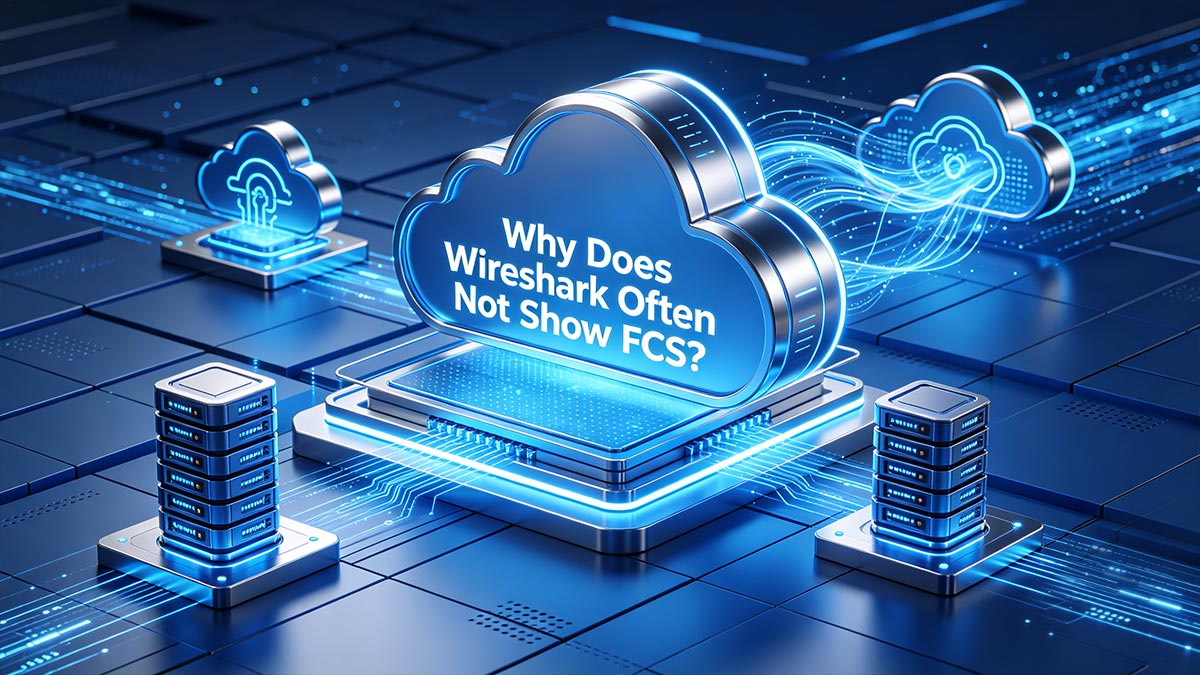
✅ Why Does Wireshark Often Not Show FCS?
Many network engineers expect to see the 4-byte Frame Check Sequence (FCS) inside packet captures, but in most cases Wireshark never receives the FCS field from the network interface card (NIC). Modern NICs and operating systems often strip the FCS before passing packets to the capture software. As a result, a packet may appear normal in Wireshark even while the switch, router, or NIC is reporting CRC/FCS errors on the physical interface.
This behavior is one of the most common sources of confusion when troubleshooting Ethernet corruption issues.
Capture vs. On-Wire Frame
The packet displayed in Wireshark is not always identical to the original Ethernet frame transmitted on the wire.
Actual Ethernet transmission:
| Ethernet Header | Payload | FCS |What Wireshark often receives:
| Ethernet Header | Payload |Because the NIC removes the FCS before forwarding the packet to the operating system, the capture software may never see the original 4-byte FCS field.
This is why:
Wireshark may show no FCS field
Packet length appears shorter
CRC errors still exist on the switch interface
NIC Offload Behavior
Modern NICs perform many Ethernet operations directly in hardware to improve performance.
Common hardware offload functions include:
FCS generation
CRC verification
TCP checksum offload
Segmentation offload
In most systems, the NIC verifies the CRC/FCS before the packet reaches Wireshark.
Process flow:
Ethernet Frame Arrives
→ NIC Validates FCS
→ FCS Removed
→ Packet Sent to OS/Wireshark
If the frame fails CRC verification, the NIC may discard the frame immediately instead of passing it to the operating system.
As a result, corrupted packets are often invisible in packet captures even though interface counters continue increasing.
Why Packet Length Looks Shorter Than Expected
Ethernet FCS adds 4 bytes to the end of the frame.
In theory:
Ethernet Frame Length
= Header + Payload + FCS
However, because the FCS is frequently removed by the NIC, Wireshark often displays a frame length that is 4 bytes shorter than the actual on-wire transmission.
Example:
Frame Type | Displayed Length |
|---|---|
Actual Ethernet frame | 1518 bytes |
Captured frame without FCS | 1514 bytes |
This difference is completely normal in most packet capture environments.
Some specialized capture adapters and monitoring systems can preserve the FCS field, but standard desktop NICs typically do not expose it to Wireshark by default.
When troubleshooting CRC/FCS issues, engineers therefore rely more heavily on:
Switch interface counters
NIC statistics
Optical module diagnostics
DOM/DDM monitoring
Physical-layer testing
rather than packet captures alone.
✅ Is a Small Number of CRC/FCS Errors Acceptable?
In production networks, even a small but recurring CRC/FCS error count is usually a sign that something is off, especially on high-speed links. Reddit discussions among network engineers repeatedly describe the “acceptable” rate as essentially zero in stable environments, because even low error rates can trigger retransmissions, latency, and application impact.
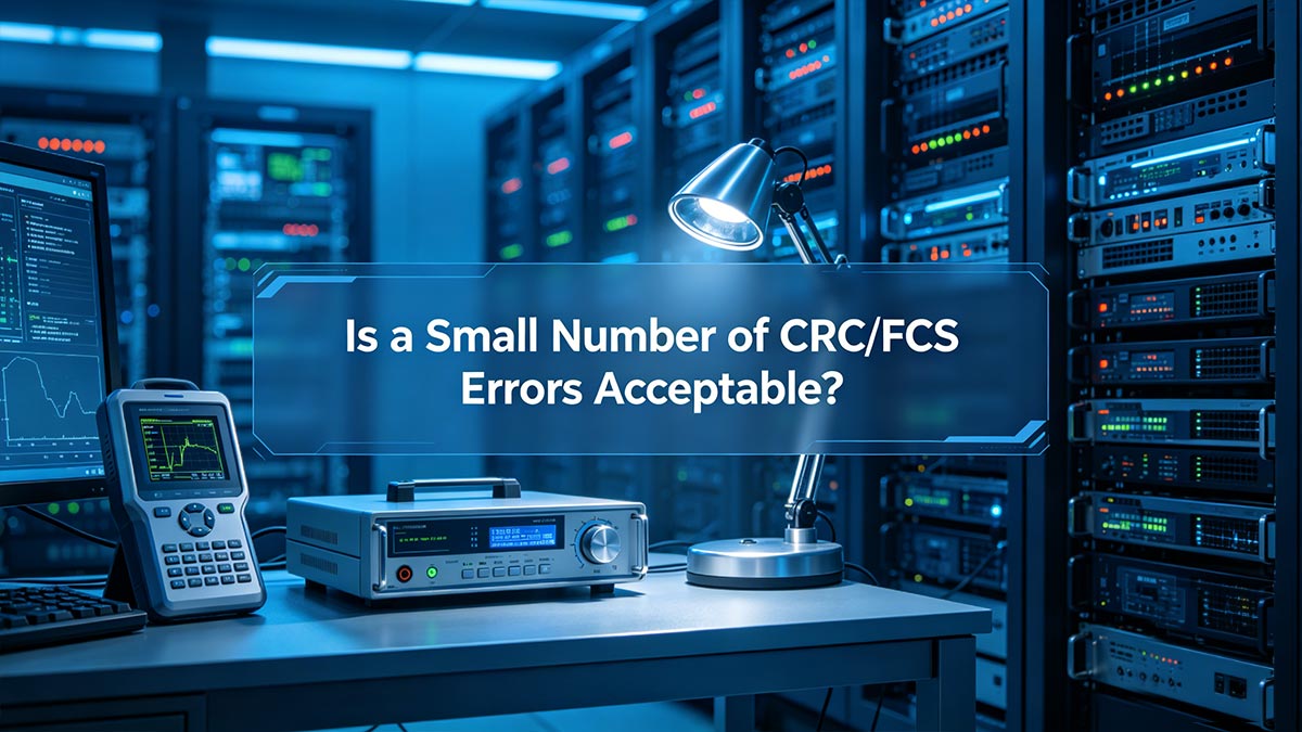
Because Ethernet automatically discards corrupted frames, recurring FCS errors should always be investigated rather than ignored.
When Zero Is the Goal
In enterprise networks and data centers, network engineers typically expect:
CRC Errors = 0
FCS Errors = 0
especially on:
Core switches
Storage networks
Spine-leaf fabrics
AI cluster interconnects
High-frequency trading networks
Stable Ethernet links should operate without continuous frame corruption.
Typical healthy interface behavior:
Interface Status | CRC/FCS Errors |
|---|---|
Normal stable link | 0 |
Occasional transient event | Very low |
Continuously increasing counters | Problem exists |
If the counters continue increasing over time, the issue is usually not considered normal.
When Intermittent Errors Become a Problem
Some environments experience occasional CRC/FCS spikes caused by:
EMI interference
Loose connectors
Aging optics
Temperature fluctuations
Poor cable quality
Even if the error rate appears low, intermittent corruption can still affect:
TCP retransmissions
Storage traffic
Voice/video quality
Database synchronization
Real-time AI workloads
Example behavior:
Low BER
→ Occasional Frame Corruption
→ Retransmissions
→ Increased Latency
In many production environments, intermittent errors become more noticeable during:
Peak traffic periods
High temperatures
Large file transfers
Bursty east-west traffic
This is why recurring CRC/FCS errors are often treated as an early-stage warning sign before a larger link failure occurs.
Why High-Speed Links Are Less Forgiving
As Ethernet speeds increase, signal integrity becomes much more sensitive.
Higher-speed links such as:
25G Ethernet
100G Ethernet
400G Ethernet
800G Ethernet
operate with:
Higher signaling rates
Tighter timing margins
Increased susceptibility to noise and jitter
General trend:
Ethernet Speed | Error Sensitivity |
|---|---|
1G | Lower |
10G | Moderate |
25G | Higher |
100G | Very high |
400G+ | Extremely sensitive |
Because of this, problems that may not affect a 1G link can easily generate CRC/FCS errors on modern high-speed Ethernet infrastructure.
Common high-speed causes include:
Dirty MPO connectors
Marginal QSFP28 optics
Poor DAC cable quality
PCB signal integrity issues
Thermal instability
Optical power imbalance
In modern data centers, repeated CRC/FCS errors on high-speed ports are usually treated as indicators of degraded link quality that require immediate investigation.
✅ Conclusion: What FCS Errors Mean for Network Reliability
Frame Check Sequence (FCS) is one of the most important integrity-checking mechanisms in Ethernet networking. By using CRC-32 verification at Layer 2, Ethernet devices can quickly detect corrupted frames before invalid data reaches higher-layer applications or services. When FCS verification fails, the issue is usually related to the physical transmission path rather than TCP or application-layer protocols.
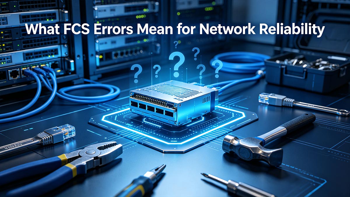
In real-world enterprise and data center environments, recurring CRC/FCS errors should never be ignored. Even a small but continuously increasing error count may indicate deeper problems such as damaged Ethernet cables, dirty fiber connectors, unstable signal integrity, failing NICs, or defective SFP, SFP+, QSFP, and QSFP28 optical modules.
As Ethernet networks continue evolving toward 100G, 400G, and AI-driven high-performance infrastructure, maintaining low Bit Error Rates (BER) and stable optical transmission becomes increasingly critical. Modern high-speed links operate with very tight signal margins, meaning even small physical-layer imperfections can quickly lead to packet corruption, retransmissions, latency increases, and application instability.
The most practical takeaway is simple:
Repeated CRC/FCS errors almost always mean the physical link deserves investigation.In most cases, the fastest troubleshooting workflow is:
Check interface counters
Replace the cable or fiber jumper
Clean and inspect connectors
Swap the optical transceiver
Review DOM/DDM diagnostics
For network engineers, data center operators, and IT administrators, FCS counters remain one of the earliest and most valuable indicators of Ethernet link health.
Recommended Resources
LINK-PP Official Store SFP Modules
Fiber Cleaning and Inspection Best Practices
Ethernet CRC/FCS Troubleshooting Checklist
Author Bio
Written by a networking infrastructure content specialist with hands-on experience in Ethernet troubleshooting, optical transceiver compatibility, fiber networking.


