


In modern digital communication, data must travel accurately between devices, servers, storage systems, and networks. Whether you are transferring files, streaming video, using Ethernet switches, or connecting high-speed SFP modules in a data center, even a single corrupted bit can cause transmission failures, packet loss, or damaged data. This is where CRC (Cyclic Redundancy Check) becomes essential.
A CRC check is one of the most widely used error-detection methods in networking and data communications. It helps devices determine whether transmitted data has been altered, corrupted, or damaged during transfer. CRC technology is commonly used in Ethernet networks, routers, switches, storage devices, industrial communication systems, fiber optics, and SFP transceivers to ensure data integrity and reliable communication.
When a system detects a mismatch during verification, it generates a CRC error. These errors often indicate problems such as damaged cables, electromagnetic interference, signal degradation, faulty hardware, incompatible SFP modules, dirty fiber connectors, or unstable network links. In enterprise environments, recurring CRC errors can reduce network performance, increase retransmissions, and cause packet drops across high-speed links.
Because CRC is deeply connected to modern networking infrastructure, users frequently search for questions such as:
What is CRC in networking?
What does a cyclic redundancy check error mean?
Is CRC better than checksum?
How do I fix CRC errors on Ethernet or fiber links?
Why do SFP modules show CRC errors?
Understanding how CRC works is important not only for network engineers and IT administrators, but also for businesses managing servers, switches, industrial equipment, and optical communication systems. As network speeds continue moving toward 10G, 25G, 40G, 100G, and beyond, reliable error detection becomes even more critical for maintaining stable data transmission.
In this guide, you will learn:
What CRC Cyclic Redundancy Check actually means
How CRC checks work in networking and data transmission
The difference between CRC and checksum methods
Common causes of CRC errors
How to troubleshoot CRC errors in Ethernet and fiber networks
Why CRC issues frequently appear in optical transceivers
Best practices to prevent CRC-related network problems
By the end of this article, you will have a clear understanding of how CRC protects data integrity and why CRC errors should never be ignored in modern network environments.
🟨 What Is CRC Cyclic Redundancy Check?
CRC (Cyclic Redundancy Check) is an error-detecting code used to verify whether digital data has been corrupted during transmission or storage. It exists because network links, storage devices, and communication systems can experience noise, interference, signal loss, or hardware faults. CRC helps devices detect damaged packets or corrupted files before the data is accepted, making it a core technology in Ethernet networks, storage systems, and SFP optical modules.
Micro Definition: CRC = Error-Detecting Code
A CRC is a mathematical method used to check whether binary data changed during transmission.
Its purpose is simple:
Detect corrupted data before the system uses it.
CRC does not repair data.
It only detects whether an error occurred.
This is why CRC is widely used in:
Ethernet networks
Routers and switches
Fiber optic communication
Why Does CRC Exist?
Digital communication is never completely error-free.
Data corruption can happen because of:
Damaged cables
Dirty fiber connectors
Faulty SFP modules
Hardware instability
Without CRC, devices would have no reliable way to identify corrupted data packets or damaged files.
Scenario | CRC Result |
|---|---|
Corrupted Ethernet frame | Error detected |
Faulty fiber transmission | Packet rejected |
Storage bit error | Integrity failure detected |
Network interference | Corrupted data identified |
Why CRC Matters in Ethernet and SFP Networks
Modern Ethernet standards developed by the Institute of Electrical and Electronics Engineers use CRC-based Frame Check Sequence (FCS) fields to detect corrupted frames.
In high-speed networks such as:
CRC errors often indicate:
Poor signal quality
Dirty optical connectors
Fiber link problems
Incompatible optical modules
CRC errors are often early warning signs of physical-layer network problems.
For network engineers, monitoring CRC counters is an important part of maintaining stable Ethernet and fiber optic links.
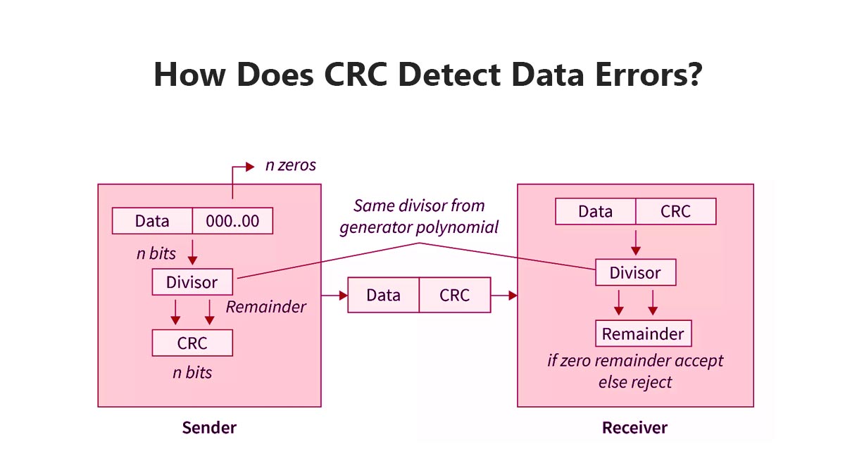
🟨 How Does CRC Detect Data Errors?
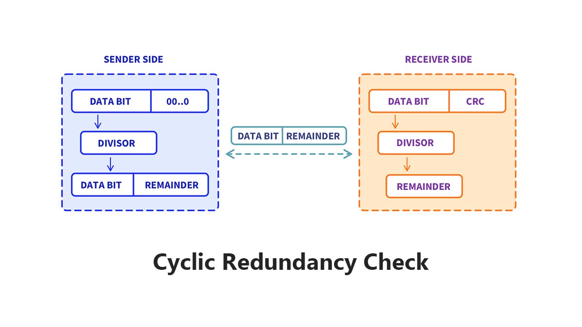
CRC detects data errors by generating a mathematical checksum value from the original data before transmission. When the data reaches the receiver, the system recalculates the CRC value and compares it with the original one. If the two values do not match, the device knows the data was corrupted during transmission or storage. This process allows Ethernet switches, routers, storage systems, and SFP optical links to detect damaged packets quickly and efficiently.
CRC Error Detection Process in 3 Steps
CRC works through a simple verification process:
Step | What Happens | Purpose |
|---|---|---|
Step 1 | The sender calculates a CRC value from the original data | Create a unique integrity check |
Step 2 | The receiver recalculates the CRC using the received data | Verify data consistency |
Step 3 | The system compares both CRC values | Detect transmission errors |
If the CRC values match: The data is considered valid.
If the CRC values do not match:
The system detects corruption.
The packet or file may be discarded or retransmitted.
Simple Example of How CRC Works
Imagine a switch sends an Ethernet frame through a fiber optic link using an SFP module.
Before Transmission
The switch:
Generates the data packet
Calculates the CRC value
Appends the CRC to the Ethernet frame
During Transmission
The signal may be affected by:
EMI interference
Optical signal loss
Dirty fiber connectors
Faulty DAC/AOC cables
Incompatible SFP modules
After Reception
The receiving device:
Recalculates the CRC value
Compares it with the original CRC
If even one binary bit changes during transmission, the CRC values become different, and the frame is marked as corrupted. CRC is designed to detect accidental data corruption, not encrypt or repair data.
Why CRC Is Effective in Ethernet Networks
Modern Ethernet standards from the Institute of Electrical and Electronics Engineers use CRC-based Frame Check Sequence (FCS) fields to verify Layer 2 frame integrity.
CRC is highly effective because it can detect:
Single-bit errors
Burst errors
Noise-related corruption
Transmission instability
In high-speed 10G, 25G, and 100G Ethernet environments, CRC checking is essential for maintaining reliable packet delivery and stable network performance.
🟨 Why Do CRC Errors Happen?
CRC errors usually do not mean the CRC system itself is broken. In most cases, a CRC error indicates that data was corrupted somewhere during transmission because of a physical-layer problem. Common causes include damaged cables, dirty fiber connectors, electromagnetic interference (EMI), signal attenuation, faulty switch ports, or incompatible SFP optical modules. In Ethernet networks, recurring CRC errors are often early signs of link instability or hardware degradation.
CRC errors are typically symptoms of transmission problems — not software problems.
CRC Error Causes and Their Impact
CRC errors occur when the received data does not match the original transmitted data.
Physical Problem | How It Causes CRC Errors | Common Environment |
|---|---|---|
Dirty fiber connector | Weakens optical signal quality | Data centers |
Damaged copper cable | Introduces packet corruption | Office Ethernet |
EMI interference | Disrupts electrical transmission | Industrial factories |
Incompatible SFP module | Causes unstable link negotiation | Enterprise switches |
Excessive transmission distance | Increases bit error rate (BER) | Long fiber runs |
Faulty switch port | Corrupts Ethernet frames | Aging hardware |
Why CRC Errors Are Common in SFP Networks
In fiber optic Ethernet environments, CRC errors are frequently linked to optical-layer issues.
For example:
Contaminated LC connectors can increase insertion loss
Poor-quality transceivers may generate unstable optical signals
Mismatched wavelengths can reduce transmission reliability
Excessive fiber bending can weaken signal integrity
This is especially important in:
10G SFP+
25G SFP28
100G QSFP28
Data center spine-leaf networks
As Ethernet speeds increase, signal tolerance margins become smaller, making CRC monitoring more critical for network reliability.
CRC Errors vs. Packet Loss
Many users confuse CRC errors with packet loss.
Micro Definition
CRC error: The device received corrupted data.
Packet loss: The packet never arrived successfully.
CRC errors often happen before packet loss becomes visible.
This is why network engineers monitor CRC counters as an early warning indicator of:
Physical-layer instability
Optical degradation
Cable failures
Port-level transmission problems
In enterprise environments, increasing CRC counts on switch interfaces usually require immediate investigation before the issue affects application performance or service availability.
🟨 What Do CRC Errors Mean on Ethernet and SFP Modules?
In Ethernet and SFP optical networks, CRC errors usually mean that data packets were corrupted during transmission. The most common root cause is poor physical-layer signal quality rather than software failure. Problems such as dirty fiber connectors, damaged cables, unstable switch ports, signal attenuation, or incompatible SFP/SFP+ and QSFP28 modules can all generate CRC frame errors on Ethernet links.
In most enterprise networks, CRC errors are physical-layer warning signs.
Why CRC Errors Matter in Ethernet Networks
Modern Ethernet networks rely on CRC-based Frame Check Sequence (FCS) verification to validate packet integrity at Layer 2.
When a switch, router, or NIC receives a frame with an invalid CRC value:
The frame is considered corrupted
The packet is discarded
Retransmissions may occur
Network performance can degrade
This is why CRC counters are commonly monitored on:
Switch ports
SFP/SFP+ uplinks
QSFP28 data center links
Fiber aggregation switches
Core Ethernet infrastructure
In high-speed 10G, 25G, 40G, and 100G Ethernet environments, recurring CRC errors usually indicate unstable signal transmission somewhere in the link.
Common CRC Error Scenarios in SFP and Ethernet Links
Device / Scenario | Common Symptoms | Possible Causes | First Thing to Check |
|---|---|---|---|
SFP+ fiber uplink | Increasing CRC counters | Dirty LC connector | Clean fiber end faces |
QSFP28 100G link | Packet drops | Excessive optical loss | Check optical power levels |
Ethernet switch port | Frame errors | Faulty port hardware | Move cable to another port |
DAC cable connection | Intermittent CRC spikes | Low-quality DAC cable | Replace DAC cable |
Long-distance fiber link | CRC + retransmissions | Signal attenuation | Verify transmission distance |
Mixed-vendor optics | Link instability | SFP compatibility issue | Test certified modules |
CRC Errors on Switch Ports
On managed Ethernet switches, CRC errors are typically visible in:
Interface statistics
Port monitoring dashboards
SNMP counters
CLI diagnostic commands
For example:
Cisco switches may show “input errors” and “CRC”
Juniper devices may display Ethernet FCS errors
MikroTik and HPE switches track frame check failures
If CRC counts continue increasing over time, network engineers usually investigate:
Fiber cleanliness
Cable integrity
Optical module compatibility
Switch port condition
EMI interference sources
Why SFP Modules Commonly Trigger CRC Errors
SFP and QSFP transceivers operate at very high signaling rates.
For example:
10G SFP+ = 10.3125 Gbps line rate
25G SFP28 = 25.78125 Gbps
100G QSFP28 uses 4 electrical lanes
At these speeds, even small physical-layer issues can corrupt packets.
Common SFP-related CRC causes include:
Poor optical alignment
Dirty fiber jumpers
Excessive insertion loss
Overheating transceivers
Unsupported optical modules
Low-quality third-party optics
This is why data centers and telecom networks often use:
DOM/DDM optical monitoring
CRC counter tracking
BER (Bit Error Rate) analysis
Optical power diagnostics
to proactively identify failing links before outages occur.
CRC Errors Are Often Early Indicators of Link Failure
CRC errors rarely appear alone.
In real-world deployments, they are often followed by:
Packet retransmissions
Throughput reduction
Latency spikes
Interface flapping
Application instability
For this reason, experienced network engineers treat recurring CRC errors as an early-stage infrastructure warning rather than a minor statistical anomaly. A rising CRC counter usually means the Ethernet link quality is deteriorating.
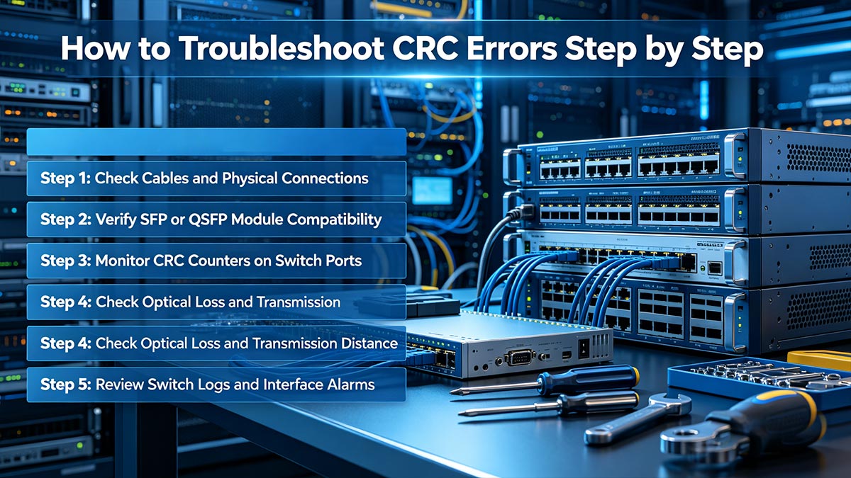
🟨 How to Troubleshoot CRC Errors Step by Step
The fastest way to troubleshoot CRC errors is to diagnose the physical layer first. In most Ethernet and SFP networks, CRC errors are caused by cabling problems, dirty fiber connectors, incompatible optical modules, signal attenuation, or failing switch ports. A structured troubleshooting process helps network engineers isolate the root cause quickly before packet loss, retransmissions, or link instability affect production traffic.
Start with the simplest physical checks before replacing hardware.
Step 1: Check Cables and Physical Connections
Physical cabling issues are one of the most common causes of CRC errors.
Inspect:
Ethernet patch cords
Fiber jumpers
DAC/AOC cables
LC connector alignment
Cable bending radius
Common symptoms:
Intermittent CRC spikes
Packet retransmissions
Link flapping
Reduced throughput
In fiber networks, even microscopic dust contamination can increase insertion loss and degrade optical signal quality.
Step 2: Verify SFP or QSFP Module Compatibility
In enterprise switches, incompatible optics frequently generate CRC and FCS errors.
Check:
Vendor compatibility
Transmission wavelength
Fiber type (SMF/MMF)
DOM/DDM diagnostics
For example:
10GBASE-SR requires multimode fiber
10GBASE-LR requires single-mode fiber
Using mismatched optics may create unstable Ethernet links even when the interface appears “up.”
Step 3: Monitor CRC Counters on Switch Ports
Managed switches continuously track:
CRC errors
FCS errors
Input errors
Interface drops
If CRC counters increase over time:
Compare both ends of the link
Move the cable to another port
Test with another transceiver
Check whether errors follow the cable or the port
Micro Definition
CRC counter: The number of corrupted frames detected on an interface.
FCS error: Ethernet frame failed CRC validation.
Step 4: Check Optical Loss and Transmission Distance
Signal attenuation becomes more important in:
25G SFP28
100G QSFP28
Long-distance fiber links
Excessive insertion loss can increase the Bit Error Rate (BER), eventually causing CRC frame corruption.
Verify:
Optical power levels
Fiber length
Connector loss
Patch panel quality
In high-speed Ethernet environments, even a small optical margin reduction may trigger recurring CRC errors.
Step 5: Review Switch Logs and Interface Alarms
Enterprise switches from companies like Cisco, Juniper Networks, and Arista Networks provide detailed interface diagnostics.
Review:
Interface reset events
Link instability warnings
DOM alarms
Temperature alerts
Packet drop statistics
Recurring CRC alarms combined with rising interface errors usually indicate a deteriorating physical link.
Real-World Engineering Insight
In practical data center deployments, CRC troubleshooting often follows a simple engineering principle:
If CRC errors move with the cable or transceiver, the problem is usually external to the switch ASIC.
Many network teams resolve persistent CRC issues by:
Replacing low-quality DAC cables
Cleaning fiber connectors
Standardizing certified SFP modules
Reducing unsupported mixed-vendor optics
In high-density 25G and 100G environments, proactive optical maintenance can significantly reduce CRC-related outages and retransmission events.
🟨 How to Prevent CRC Errors in High-Speed Networks
The best way to prevent CRC errors is to maintain stable physical-layer signal quality across the entire Ethernet link. In high-speed 10G, 25G, 100G, and 400G networks, CRC issues are commonly prevented by using compatible SFP/QSFP modules, keeping fiber connectors clean, controlling optical loss, monitoring interface CRC counters, and standardizing cabling and transceiver deployments. Preventive maintenance is far more effective than troubleshooting recurring packet corruption after failures occur.
Most recurring CRC errors can be prevented through proper optical and cabling practices.
1. Use Matching Optical Modules and Cabling
One of the most common causes of CRC errors is mismatched or low-quality optical hardware.
Always verify:
SFP/SFP+ compatibility
Fiber type (SMF or MMF)
Wavelength matching
Connector type
Ethernet standard support
For example:
Optical Standard | Fiber Type | Typical Distance |
|---|---|---|
10GBASE-SR | Multimode Fiber (MMF) | Up to 300 m |
10GBASE-LR | Single-Mode Fiber (SMF) | Up to 10 km |
MMF | Up to 100 m | |
100G QSFP28 LR4 | SMF | Up to 10 km |
Using unsupported optics or incorrect fiber types can create intermittent CRC and FCS errors even when the link remains operational.
2. Keep Fiber End Faces Clean
Dirty optical connectors are one of the leading causes of CRC errors in data centers.
Contamination may include:
Dust particles
Finger oils
Cleaning residue
Airborne debris
Even microscopic contamination can:
Increase insertion loss
Reduce optical signal quality
Raise Bit Error Rate (BER)
Trigger CRC frame corruption
Best Practice
Inspect and clean:
LC connectors
MPO/MTP interfaces
Patch panels
Fiber jumpers
before installation and during maintenance cycles.
3. Monitor CRC Counters Before Failures Occur
Experienced network teams do not wait for outages before checking CRC statistics.
Modern switches from Cisco, Juniper Networks, and Arista Networks support continuous interface monitoring for:
CRC errors
FCS errors
Packet drops
BER trends
Optical DOM metrics
Micro Definition
CRC counter: Tracks the number of corrupted Ethernet frames detected on an interface.
A slowly increasing CRC counter often indicates:
Early optical degradation
Cable aging
Port instability
Weak signal margins
Detecting these trends early helps prevent large-scale network failures.
4. Control Optical Loss and Link Budget
High-speed Ethernet links have strict optical power requirements.
For stable transmission:
Total insertion loss must remain within specification
Fiber bending should be minimized
Patch panel loss should be controlled
Connector reflections should be reduced
In 25G and 100G Ethernet environments, small optical margin losses may significantly increase CRC errors.
5. Standardize Infrastructure Across the Network
Mixed-vendor deployments sometimes create interoperability issues that increase CRC instability.
Many enterprise operators reduce CRC-related problems by standardizing:
SFP vendors
DAC cable types
Fiber infrastructure
Switch firmware versions
Optical monitoring policies
In high-density AI clusters, cloud data centers, and telecom environments, proactive CRC prevention is considered part of long-term network reliability engineering rather than simple troubleshooting.
🟨 FAQ About CRC Errors
Q1: Why am I suddenly seeing CRC errors on my switch port?
CRC errors usually mean the switch is receiving corrupted Ethernet frames. In most cases, the problem is physical-layer related, such as dirty fiber connectors, damaged cables, unstable SFP modules, or signal attenuation.
In enterprise networks, rising CRC counters are often early warning signs of link degradation before packet loss becomes visible.
A CRC error usually points to a transmission problem, not a software problem.
Q2: Is CRC better than checksum for detecting network errors?
Yes. CRC is more reliable than a traditional checksum because it can detect more complex transmission corruption patterns, including burst errors commonly found in Ethernet and optical networks.
Technology | Detection Capability | Common Usage |
|---|---|---|
Checksum | Basic | Files, simple protocols |
CRC | Advanced | Ethernet, SFP networks |
ECC | Detection + correction | Memory, storage |
This is why modern Ethernet standards use CRC-based Frame Check Sequence (FCS) validation.
Q3: Can bad SFP modules cause CRC errors?
Yes. Unstable or incompatible SFP/SFP+ modules are common causes of CRC errors in fiber networks.
Typical causes include:
Dirty LC connectors
Poor optical signal quality
Unsupported optics
Low-quality DAC cables
Overheating transceivers
At 10G, 25G, and 100G Ethernet speeds, even small signal-quality issues can corrupt packets.
Q4: Why do CRC errors happen more often in 25G and 100G networks?
Higher-speed Ethernet links have much smaller signal tolerance margins.
In 25G SFP28 and 100G QSFP28 environments, minor optical loss, connector contamination, or insertion loss can quickly increase the Bit Error Rate (BER), leading to CRC frame errors.
Higher network speeds require cleaner and more stable physical links.
Q5: Can CRC errors slow down a network even if the link stays up?
Yes. A link may remain operational while corrupted frames are continuously discarded and retransmitted.
This can cause:
Higher latency
Reduced throughput
TCP retransmissions
Application instability
In many cases, users notice “slow network performance” before the interface actually goes down.
Q6: What is the fastest way to fix CRC errors on a fiber link?
Most engineers troubleshoot CRC errors in this order:
Priority | Recommended Action |
|---|---|
1 | Clean fiber connectors |
2 | Replace patch cable |
3 | Swap SFP module |
4 | Check optical power levels |
5 | Test another switch port |
This physical-layer-first approach resolves most CRC issues in Ethernet and SFP networks.
🟨 Conclusion: Why CRC Monitoring Matters in Modern Ethernet and SFP Networks
CRC (Cyclic Redundancy Check) is one of the most important mechanisms for protecting data integrity in modern Ethernet communication. Whether in enterprise switches, industrial networks, AI clusters, or high-speed fiber infrastructure, CRC helps detect corrupted packets before they affect applications, storage systems, or network stability.

In real-world deployments, recurring CRC errors are rarely random. They are usually early indicators of:
Poor signal quality
Dirty fiber connectors
Damaged cabling
Optical attenuation
Unstable switch ports
Incompatible SFP modules
As networks continue moving toward 25G, 100G, and 400G Ethernet, maintaining stable physical-layer performance becomes increasingly important. Proactive CRC monitoring, proper optical maintenance, and reliable transceiver compatibility are now essential parts of data center and telecom network operations.
Stable optical links produce stable CRC performance.
For businesses building reliable fiber Ethernet infrastructure, choosing high-quality and fully compatible optical transceivers is one of the most effective ways to reduce CRC-related network issues.
Explore enterprise-grade SFP, SFP+, SFP28, and QSFP optical transceivers at the LINK-PP Official Store for stable, high-performance Ethernet connectivity.


