

In fiber optic networks, signal power has to stay within a narrow operating window. If the received optical power is too low, the link may become unstable or fail. If it is too high, the receiver can be overloaded and performance can suffer. That is why optical power measurement is one of the most important tasks in installation, validation, and troubleshooting. An optical power meter, often shortened to OPM, is the instrument used for that job. It measures optical power directly, and it is also used in loss testing when paired with a stable light source.
For SFP testing, the OPM is especially valuable because it helps verify the actual signal leaving a transceiver and the signal arriving at the receiver end. In practical field use, technicians can connect a power meter directly to the transmitter output or place it at the point where the optical receiver would be, then read the result in dBm. That makes it a simple but essential tool for checking whether an SFP module is operating within specification.
✅ What Is OPM Optical Power Meter?
An optical power meter is a test device that measures the strength of light traveling through a fiber optic system. In fiber testing, the result is usually displayed as dBm for absolute optical power or dB for relative loss. Industry guidance commonly describes dBm as power referenced to 1 milliwatt, while dB expresses the difference between two levels.
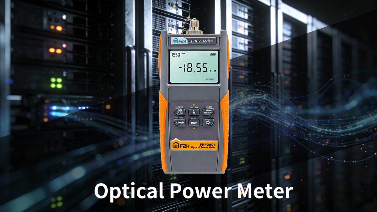
In simple terms, an OPM acts like a “light meter for fiber optics”, allowing engineers to determine how strong or weak an optical signal is at any point in the network.
Core Functions:
Measure transmitter output power
Measure received optical power
Calculate optical loss (when used with a light source)
Verify link performance against specifications
OPM in SFP Testing
Optical modules are designed to operate within specific optical power ranges. During testing, a power meter is used to confirm that the module’s output aligns with the expected specification and that the received signal does not exceed safe limits. Fluke Networks specifically notes that when checking an SFP, reading in dBm reflects the way many SFP specifications are written.
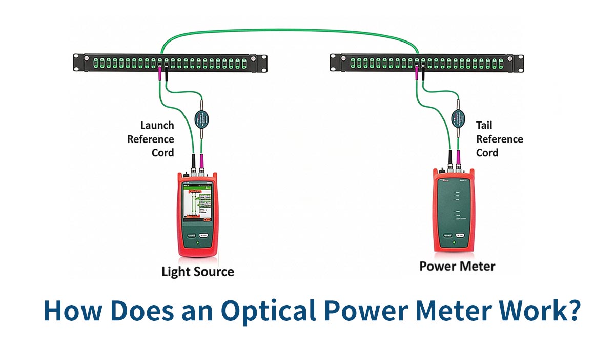
✅ How Does an Optical Power Meter Work?
An optical power meter works by converting incoming optical energy into an electrical measurement through a photodiode detector. The detector senses the light level, and the meter displays the result in the selected unit. This is why the instrument can be used both in live network checks and in lab-style loss measurements.
Working Principle
Light enters the OPM through a fiber connector
A photodiode converts optical energy into electrical current
The device calculates and displays power in dBm or dB
Absolute Power and Relative Loss
An OPM is used in two common ways:
Absolute power measurement: the meter reads the actual optical signal level, usually in dBm.
Relative loss measurement: the meter compares the received level to a reference value and shows loss in dB.
This distinction matters because absolute power tells you what the module is delivering or receiving, while relative loss tells you how much power is being lost across the fiber link.
Wavelength Settings and Calibration
An optical power meter must be matched to the operating wavelength of the network. VIAVI notes common settings such as 850 nm and 1300 nm for multimode fiber, and 1310 nm and 1550 nm for single-mode fiber. In practice, the wavelength setting should match the actual service wavelength to ensure meaningful results.
Calibration and detector performance also matter. Modern meters can cover a wide dynamic range and may support single-mode, multimode, or WDM applications. For example, VIAVI and EXFO list instruments with broad ranges for absolute power and insertion loss testing, showing that different products are built for different field or lab needs.
Important Parameters
Wavelength Calibration: Typically 850 nm, 1310 nm, 1550 nm
Measurement Range: e.g., -70 dBm to +10 dBm
Accuracy: Typically ±0.2–0.5 dB
Connector Interface: LC, SC, FC
✅ Why Optical Power Measurement Matters in Fiber Optics
Optical power measurement is not just a maintenance task. It is a core part of fiber design, installation, and troubleshooting because fiber links are sensitive to both loss and overload. VIAVI describes optical loss as the decrease in power as light travels through fiber, and explains that the accurate way to measure it is to inject a known light level and measure what arrives at the other end.
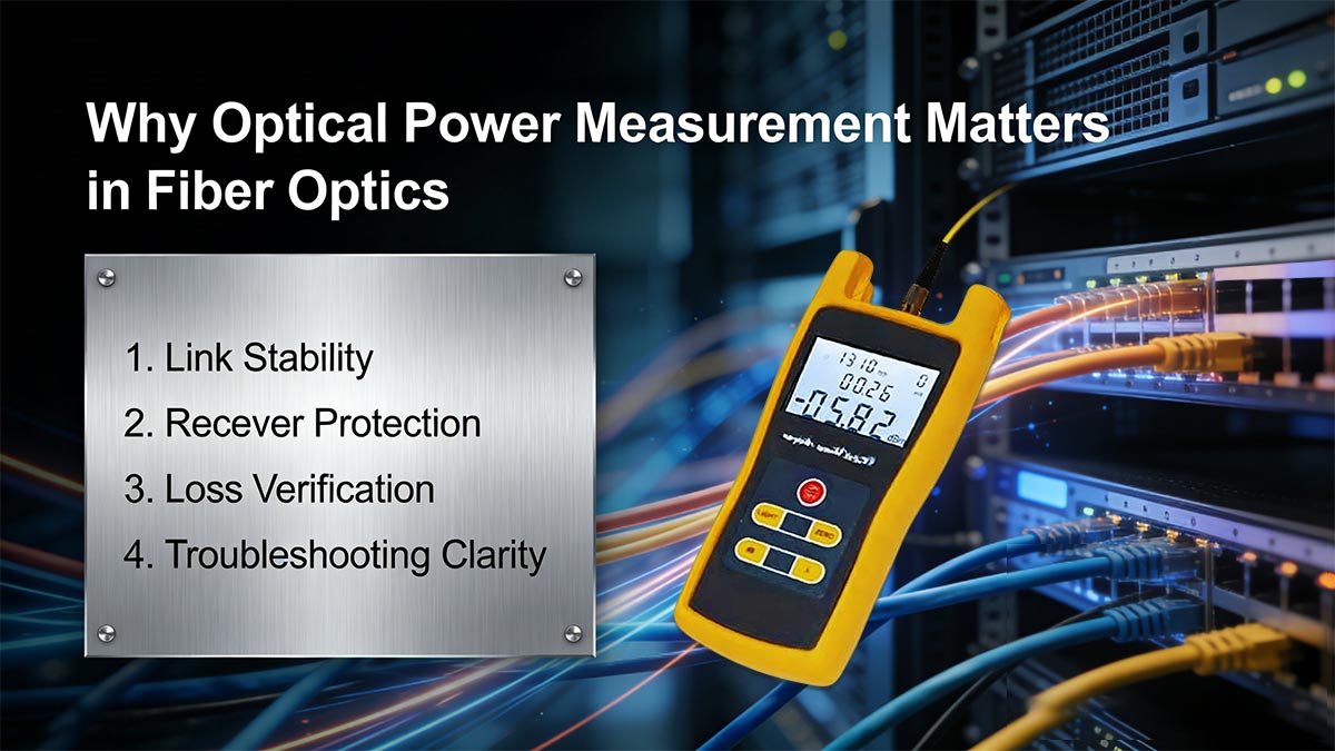
1. Link Stability
A network is more stable when its optical power stays within the target range. If the signal is too weak, the receiver may have trouble detecting data reliably. If it is too strong, the receiver can saturate. Measuring power helps engineers keep the link balanced.
2. Receiver Protection
Optical receivers are designed for a specific input range. Exceeding that range can reduce performance and may create overload conditions. Using an OPM during installation or troubleshooting helps confirm that the receiver is not being driven too hard.
3. Loss Verification
When used together with a stable optical light source, an OPM becomes part of an optical loss test set (OLTS). That pair is the standard approach for measuring insertion loss across a fiber link. VIAVI specifically notes that the source and power meter on opposite ends of the link provide the loss value.
4. Troubleshooting Clarity
If a link fails, power measurements quickly reveal whether the problem is caused by excessive loss, poor connector quality, wrong wavelength selection, or a transceiver that is not producing the expected output. That makes the OPM one of the fastest tools for isolating optical-layer issues.
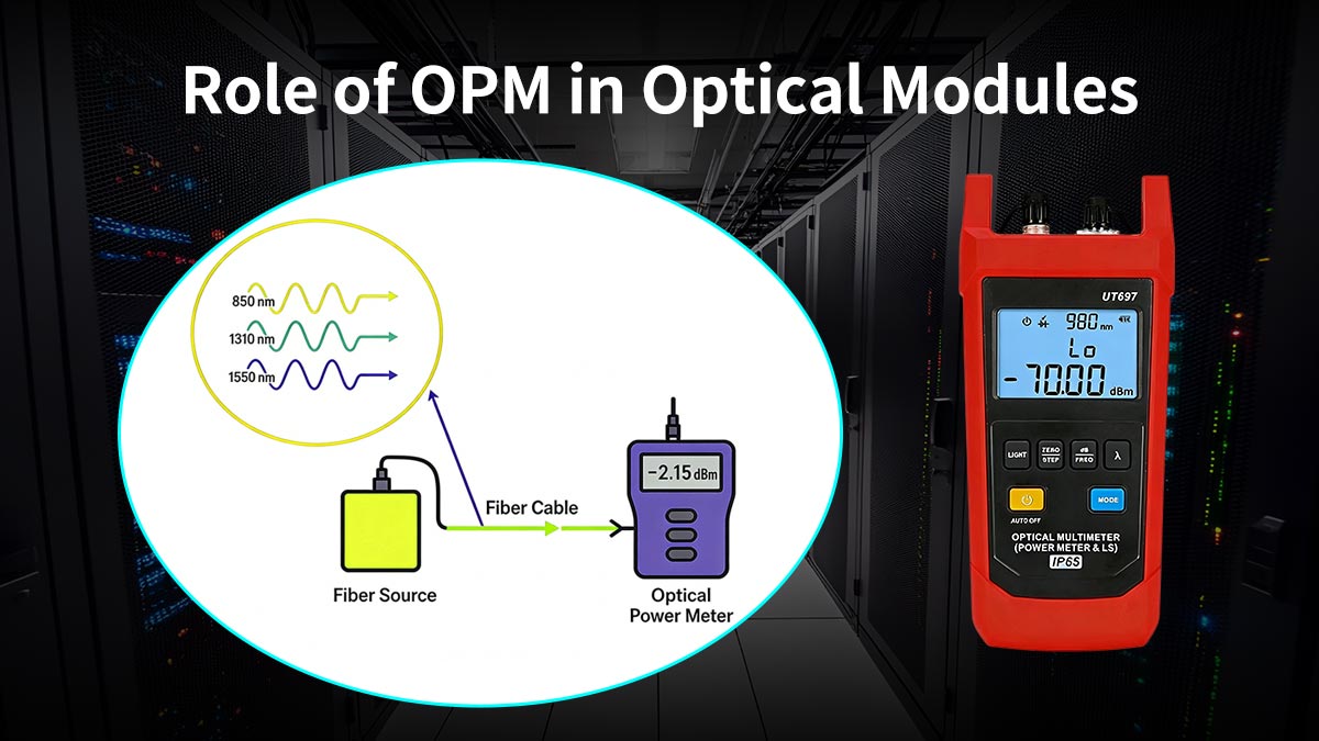
✅ Role of OPM in Optical Modules
An Optical Power Meter (OPM) plays a critical role in the testing, validation, and maintenance of optical transceivers such as SFP transceiver and QSFP module. Because these modules must operate within strict optical power ranges, accurate measurement is essential to ensure proper functionality and long-term reliability.
🔹 Measuring Transmitter Output Power
One of the primary roles of an OPM is to verify the actual optical power emitted by the transmitter (Tx). By connecting the meter directly to the module output, engineers can confirm whether the signal falls within the specified range defined in the datasheet.
🔹 Checking Receiver Input Power
On the receiving side, the OPM is used to measure incoming optical power to ensure it stays within:
Receiver sensitivity (minimum level)
Overload threshold (maximum level)
Maintaining this balance is crucial for avoiding link instability or performance degradation.
🔹 Supporting Optical Module Testing and Validation
During lab testing and production validation, OPMs are used to:
Confirm module compliance with standards
Measure optical output consistency
Evaluate link margin and performance
🔹 Troubleshooting Optical Links
When issues arise, such as link failure or high error rates, an OPM helps quickly identify whether the problem is related to:
Low optical power (excessive loss)
High optical power (receiver saturation)
Faulty connectors or fiber paths
Key Insight
The OPM is not just a measurement tool—it acts as a diagnostic bridge between optical modules and real-world network performance, enabling engineers to ensure that every link operates within safe and optimal power conditions.
🔹 When Do You Need an OPM for Optical Module Testing?
A power meter is useful any time you need to know whether the optical layer is operating inside specification.
Use an Optical Power Meter When:
installing a new fiber link,
checking received power at the far end of the link,
troubleshooting intermittent link failures,
or performing maintenance on an existing network.
Use OPM Especially in these Cases:
Short links with strong transmitters, where overload risk is higher.
Long links with multiple patch points, where excessive loss may reduce receiver margin.
Lab and manufacturing environments, where repeatability and precision matter.
PON, FTTx, enterprise, and data-center work, where power verification is part of normal acceptance testing.
✅ OPM vs. Optical Light Source vs. OLTS: What Is the Difference?
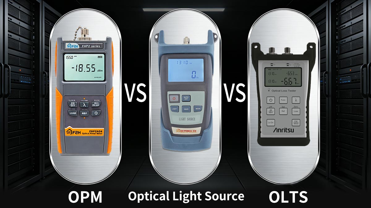
These three tools are related, but they do different jobs.
Optical Power Meter
Measures the optical power at a point in the link. It tells you how strong the light is.
Optical Light Source
Produces a stable optical signal for testing. It is often used as the transmitter side in loss measurements.
Optical Loss Test Set (OLTS)
Combines a light source and a power meter to measure insertion loss across a fiber link. VIAVI describes this as the most accurate method for measuring overall optical loss because the source and receiver are placed on opposite ends of the fiber.
Device | Function | Use Case |
|---|---|---|
OPM | Measures optical power | Power verification |
Light Source | Emits stable optical signal | Signal injection |
OLTS | Combines both | Insertion loss testing |
Practical Takeaway
If you only need to know how much power is present, use an OPM. If you need to measure how much power is lost across a link, use an OPM together with a light source as an OLTS.
✅ Types of Optical Power Meters and How to Choose the Right One
Different fiber optic environments require different types of Optical Power Meters (OPMs), and selecting the right one depends on your specific testing needs, accuracy requirements, and deployment scenarios. Understanding both the available types and the key selection criteria ensures reliable measurements and optimal performance in optical module testing.
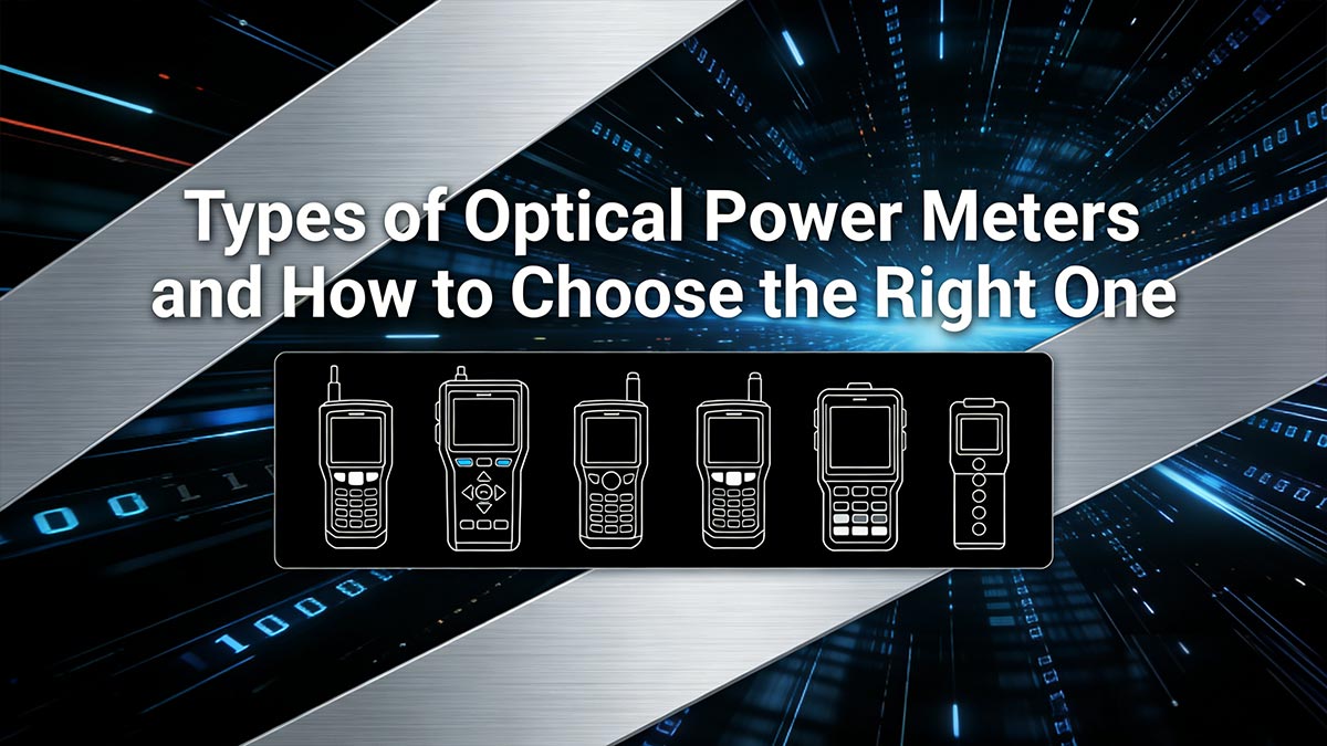
Common Types of Optical Power Meters
Handheld OPM
Compact, portable, and easy to use, handheld optical power meters are the most common choice for field technicians. They are ideal for:
Fiber installation
On-site troubleshooting
Routine maintenance
These devices are designed for quick measurements and everyday network testing.
High-Precision Lab OPM
These meters are built for environments that require higher accuracy and advanced measurement capabilities. Typical features include:
Faster sampling rates
Wider dynamic range
Higher measurement precision
They are commonly used in:
Laboratory testing
Manufacturing validation
Optical module performance evaluation
PON Power Meter and Network-Specific Meters
Specialized OPMs are designed for specific network types, such as Passive Optical Networks (PON). These meters can:
Measure multiple wavelengths simultaneously
Support live network testing
Integrate inspection and diagnostic functions
They are widely used in:
FTTH deployments
Telecom access networks
Integrated test workflows
Key Factors for Choosing the Right Optical Power Meter
1. Wavelength Support
Ensure the OPM supports the wavelengths used in your system, such as 850 nm, 1310 nm, or 1550 nm.
2. Measurement Range
Select a meter that can accurately measure both:
High transmitter output power
Low received signal levels
3. Connector Compatibility
Verify that the device supports your connector types, including:
SC
FC
This ensures seamless integration into your testing setup.
4. Accuracy and Calibration
For lab testing and production environments, high accuracy and proper calibration are critical. Look for:
Low measurement uncertainty
Stable calibration intervals
5. Application Environment
Choose based on where and how the OPM will be used:
Field service → handheld, rugged design
Data center → fast, reliable testing
Manufacturing → high precision and automation support
Key Insight:
The best Optical Power Meter is not simply the most advanced one—it is the one that aligns with your network requirements, optical module specifications, and real-world testing conditions.
✅ Common Problems Solved by OPM in Optical Links
A power meter solves several common optical-layer problems that appear in real deployments.
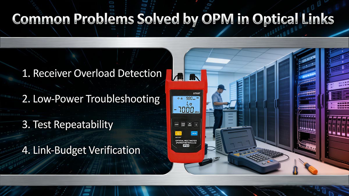
1. Receiver Overload Detection
If too much power reaches the receiver, an OPM can reveal the condition before the link becomes unstable or the module is stressed.
2. Low-Power Troubleshooting
If the received signal is too weak, the meter can help identify whether the issue is caused by high loss, a dirty connector, a damaged fiber, or a weak transmitter.
3. Test Repeatability
In lab and manufacturing environments, consistent optical power measurement keeps results comparable across runs and across devices.
4. Link-Budget Verification
Engineers use OPM readings to confirm whether the measured power matches the planned link budget and whether the system has enough margin for stable operation.
✅ Conclusion: Why OPM Is Essential for Optical Module Performance
An Optical Power Meter (OPM) is one of the most important instruments in fiber optic testing because it gives direct visibility into optical signal strength. It supports transmitter verification, receiver protection, loss testing, and day-to-day troubleshooting. For SFP testing in particular, it helps engineers confirm that the module is operating inside the right power window and that the link is behaving as expected.
In practice, a reliable optical network depends on good components, a correct link budget, and accurate measurement. The OPM sits at the center of that process, making it a foundational tool for installation teams, lab engineers, and network operators alike.
For dependable, standards-compliant SFP modules and connectivity solutions, explore the LINK-PP Official Store to support your fiber optic testing and deployment needs.
Better measurement leads to better network performance. Choosing the right OPM and using it correctly can make SFP testing faster, clearer, and more dependable.


