


In modern networks—from enterprise data centers to telecom infrastructure—the SFP (Small Form-factor Pluggable) transceiver is a critical component that directly impacts link stability, data integrity, and overall network uptime. Yet in real-world deployments, many connectivity issues—such as intermittent link drops, high bit error rates, or complete link failure—can often be traced back to insufficient or improper SFP testing.
That’s why understanding how to test an SFP transceiver is no longer just a task for lab engineers. It has become essential knowledge for:
Network engineers troubleshooting live systems
IT buyers evaluating module quality before procurement
System integrators ensuring compatibility across multi-vendor environments
This guide is designed to bridge the gap between theory and practical testing workflows. Instead of vague explanations, you’ll learn:
What specific instruments are required for accurate SFP testing
Which optical, electrical, and compatibility parameters truly matter
How to apply industry-standard testing methods used in professional labs
What hidden failure risks (like thermal instability or EEPROM mismatch) to watch for
Unlike generic overviews, this article follows a real lab testing logic aligned with standards from organizations like IEEE and MSA, while also incorporating practical insights from field deployments—where passing a basic test does not always guarantee reliable performance.
Testing an SFP transceiver is not just about checking if it “works”—it’s about verifying performance margins, compatibility, and long-term reliability under real conditions.
By the end of this guide, you’ll have a clear, step-by-step understanding of SFP testing, enabling you to:
Diagnose issues faster
Reduce deployment risks
Select higher-quality, fully tested modules with confidence
Let’s start by understanding what an SFP transceiver actually is—and why proper testing is critical before any deployment.
🚩 What Is an SFP Transceiver and Why SFP Testing Matters
Although SFP modules are designed to be standardized and hot-swappable, their real-world performance can vary due to differences in manufacturing quality, optical components, and compatibility coding.
In high-speed environments, even small deviations in optical power, signal integrity, or temperature stability can lead to link failures, data errors, or unexpected downtime. This section explains the role of SFP transceivers in networking and highlights the key risks that effective testing helps prevent—laying the foundation for all the testing methods discussed later.

What Is an SFP Transceiver?
An SFP (Small Form-factor Pluggable) transceiver is a compact, hot-swappable module used to connect network devices—such as switches, routers, and servers—to fiber optic or copper cabling. It serves as the interface between electrical signals inside the device and optical (or electrical) signals transmitted over the network medium.
In simple terms, an SFP module performs two core functions:
Transmit (Tx): Converts electrical signals into optical signals (for fiber links)
Receive (Rx): Converts incoming optical signals back into electrical signals
SFP transceivers are widely used across:
Data centers
Enterprise LANs
Telecommunications networks
They follow standardized specifications defined by organizations like MSA and IEEE, enabling interoperability across different vendors—at least in theory.
Why SFP Testing Matters in Real-World Networks
Although SFP modules are standardized, real-world performance can vary significantly depending on manufacturing quality, compatibility coding, and operating conditions. This is where proper testing becomes critical.
1. Preventing Network Failures Before Deployment
Untested or poorly tested modules can cause:
Link failures (no connection established)
Intermittent disconnections
Packet loss and unstable throughput
A basic “link-up” status does not guarantee stable operation. Only proper testing—such as BER and optical power validation—can confirm reliability.
2. Ensuring Optical Performance Meets Specifications
Each SFP module must operate within strict optical parameters, including:
Transmit power (Tx)
Receiver sensitivity (Rx)
Wavelength accuracy
If these values drift outside acceptable ranges, the result can be:
Reduced transmission distance
Increased error rates
Complete signal loss
Testing ensures the module meets its designed optical budget and margin.
3. Avoiding Compatibility Issues Across Vendors
In multi-vendor environments, SFP modules must work seamlessly with switches from companies like Cisco or Juniper Networks.
However, compatibility depends on more than physical standards:
EEPROM coding must match vendor requirements
Firmware behavior must align with host expectations
Without proper compatibility testing, you may encounter:
“Unsupported transceiver” errors
Disabled ports
Reduced functionality (e.g., monitoring disabled)
4. Detecting Hidden Reliability Risks
Some issues only appear under stress conditions:
Overheating (common in high-power or RJ45 SFP modules)
Signal degradation over time
Early component failure
These risks are typically uncovered through:
Temperature testing
Burn-in (aging) tests
Long-duration BER testing
5. Reducing Long-Term Operational Costs
Failing modules lead to:
Increased maintenance costs
Downtime and SLA penalties
Higher return (RMA) rates
By implementing proper SFP testing, organizations can:
Improve network stability
Reduce troubleshooting time
Extend equipment lifespan
An SFP transceiver is not just a plug-and-play component—it is a precision optical device that must be thoroughly tested to ensure performance, compatibility, and long-term reliability.
In the next section, we’ll break down the exact instruments required to test an SFP transceiver, from basic optical tools to advanced lab equipment used in professional validation environments.
🚩 How to Test an SFP Transceiver: Core Test Instruments
To accurately evaluate an SFP transceiver, engineers rely on a combination of optical, electrical, and protocol-level instruments. Each tool targets a specific aspect of performance—together forming a complete validation system aligned with standards from IEEE and MSA.

Below is a breakdown of the core test instruments required in a professional SFP testing workflow.
1. Optical Power Meter (OPM)
The Optical Power Meter is the most fundamental tool in SFP testing.
Purpose:
Measure transmit (Tx) output power
Verify received (Rx) optical power
Why it matters:
Confirms whether the module operates within its specified optical budget
Helps quickly identify weak transmitters or excessive link loss
Often used as the first diagnostic tool in troubleshooting.
2. Optical Spectrum Analyzer (OSA)
The Optical Spectrum Analyzer (OSA) provides detailed insight into the optical signal.
Purpose:
Measure center wavelength (e.g., 850 nm / 1310 nm / 1550 nm)
Analyze spectral width and side modes
Evaluate optical signal purity
Why it matters:
Ensures compliance with standard wavelength specifications
Detects issues like wavelength drift or unstable lasers
3. Variable Optical Attenuator (VOA)
The VOA is used to simulate real-world transmission loss.
Purpose:
Gradually reduce optical signal strength
Test receiver sensitivity limits
Why it matters:
Helps determine the minimum Rx power threshold
Critical for validating performance over long distances
4. Bit Error Rate Tester (BERT)
The BERT is essential for validating data transmission quality.
Purpose:
Generate test patterns (e.g., PRBS31)
Measure bit error rate (BER) over time
Why it matters:
Provides a quantitative measure of link reliability
Industry benchmark: BER ≤ 10⁻¹²
👉 A module may “link up” but still fail BER requirements—this tool reveals that.
5. High-Speed Oscilloscope / Digital Communication Analyzer (DCA)
These instruments are used for signal integrity analysis.
Purpose:
Capture eye diagrams
Measure:
Rise/fall time
Noise
Why it matters:
Visualizes signal quality in real time
Ensures compliance with IEEE eye mask standards
6. I²C / EEPROM Analyzer
This tool interfaces with the SFP’s internal memory.
Purpose:
Read/write EEPROM data
Verify DDM/DOM (Digital Diagnostics Monitoring)
Why it matters:
Ensures correct:
Vendor identification
Calibration data
Compatibility coding
👉 Critical for avoiding “unsupported transceiver” issues.
7. Host Test Board / Evaluation Platform
The host test board simulates real network equipment.
Purpose:
Provide electrical interface to the SFP module
Enable controlled testing outside of a full switch/router
Why it matters:
Allows repeatable lab testing conditions
Used for firmware validation and debugging
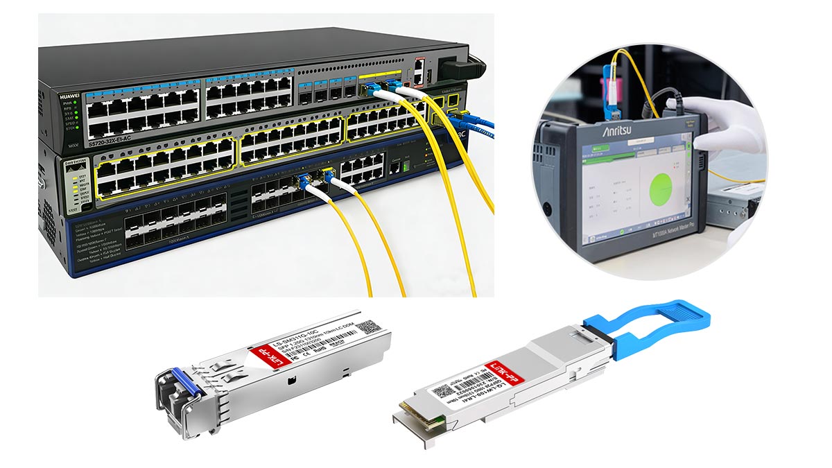
8. Optional but Common: Real Network Switches
For full validation, engineers often test modules in actual devices from vendors like Cisco or Juniper Networks.
Purpose:
Verify plug-and-play compatibility
Test real-world link behavior
No single instrument can fully validate an SFP transceiver.
A reliable test setup combines optical measurement, electrical validation, and protocol-level verification.
Optical tools → Measure power, wavelength, signal quality
Electrical tools → Ensure data integrity (BER, jitter)
Interface tools → Validate compatibility and diagnostics
Together, these instruments form a complete SFP testing ecosystem used in professional labs and high-quality manufacturing environments.
In the next section, we’ll dive deeper into the specific optical test items and parameters that define whether an SFP module truly meets performance standards.
🚩 Optical Test Items for SFP Modules
Optical performance is the core of SFP transceiver testing. Even if a module powers on and establishes a link, poor optical characteristics can lead to high error rates, reduced transmission distance, or unstable connections.
To ensure reliable operation, engineers evaluate several key optical parameters, each directly impacting signal quality and link performance.
1. Transmit Optical Power (Tx Power)
What it is:
The optical power level emitted by the SFP transmitter, typically measured in dBm.
Why it matters:
Determines how far the signal can travel
Must fall within a defined range (e.g., −9.5 dBm to −3 dBm for certain standards)
Test method:
Measure output using an Optical Power Meter (OPM)
Compare against module specifications
Too low: signal may not reach the receiver
Too high: can overload or damage the receiver
2. Receiver Sensitivity (Rx Sensitivity)
What it is:
The minimum optical power level at which the receiver can correctly detect data at an acceptable error rate.
Why it matters:
Defines the lower limit of reliable signal reception
Critical for long-distance or high-loss links
Test method:
Use a Variable Optical Attenuator (VOA) to gradually reduce input power
Monitor BER using a BERT
Record the lowest power level that meets BER ≤ 10⁻¹²
3. Center Wavelength
What it is:
The operating wavelength of the optical signal (e.g., 850 nm, 1310 nm, 1550 nm).
Why it matters:
Must match fiber type and system design
Incorrect wavelength can cause:
High attenuation
Compatibility issues
Test method:
Measure using an Optical Spectrum Analyzer (OSA)
4. Extinction Ratio
What it is:
The ratio between optical power levels of logical “1” and “0”.
Why it matters:
Indicates signal clarity and modulation quality
A low extinction ratio leads to:
Poor signal distinction
Increased bit errors
Test method:
Derived from eye diagram analysis
Measured using a DCA or oscilloscope
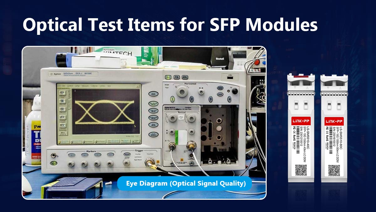
5. Eye Diagram (Optical Signal Quality)
What it is:
A visual representation of the signal over time, showing how clearly bits can be distinguished.
Why it matters:
Provides a comprehensive view of:
Jitter
Noise
Key indicators:
Wide open eye: good signal quality
Closed eye: high noise and errors
Test method:
Capture using high-speed oscilloscope or DCA
Compare against IEEE-defined eye masks
6. Optical Loss Margin (Link Budget)
What it is:
The difference between:
Transmit power (Tx)
Receiver sensitivity (Rx)
Minus total link loss
Formula concept:
Loss Margin = Tx Power – Link Loss – Rx Sensitivity
Why it matters:
Determines whether the link will remain stable under real conditions
Accounts for:
Connector loss
Aging and environmental factors
A positive margin ensures reliable operation
A low or negative margin leads to intermittent failures
Optical testing is not just about meeting specifications—it’s about ensuring sufficient performance margin for real-world conditions.
The most critical parameters—Tx power, Rx sensitivity, wavelength, extinction ratio, and eye quality—work together to define whether an SFP module can deliver:
Stable links
Low error rates
Long-term reliability
In the next section, we’ll move beyond optics and examine electrical and signal integrity testing, where high-speed data performance is validated at the physical layer.
🚩 Electrical and Signal Integrity Test Methods
While optical parameters determine how light is transmitted, electrical and signal integrity testing ensures that high-speed data is accurately encoded, transmitted, and recovered. This is especially critical for 10G, 25G, and higher-rate SFP modules, where even small distortions can cause significant data errors.
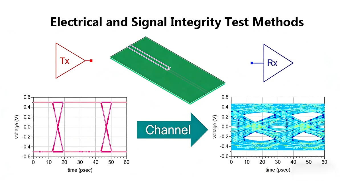
Below are the key electrical test methods used to validate SFP transceiver performance.
1. Bit Error Rate (BER) Testing
What it is:
BER measures the ratio of incorrectly received bits to total transmitted bits.
Why it matters:
It is the most important indicator of link reliability
Even a small increase in BER can lead to:
Packet loss
Retransmissions
Network instability
Test method:
Use a Bit Error Rate Tester (BERT)
Generate a standard test pattern (e.g., PRBS31)
Transmit through the SFP link and measure errors over time
Typical requirement:
BER ≤ 10⁻¹² (or better for high-performance systems)
A module can appear “normal” but still fail under BER testing—this is why it’s essential.
2. Jitter Measurement
What it is:
Jitter refers to timing variations in the signal transitions.
Why it matters:
Excessive jitter reduces signal clarity
Can cause incorrect bit interpretation at the receiver
Types of jitter:
Random jitter (RJ)
Deterministic jitter (DJ)
Test method:
Measure using a high-speed oscilloscope or DCA
Analyze total jitter and its components
3. Rise and Fall Time
What it is:
The time it takes for a signal to transition between logic states (0 → 1 and 1 → 0).
Why it matters:
Slow transitions can:
Blur signal edges
Increase inter-symbol interference (ISI)
Test method:
Capture waveform using an oscilloscope
Measure transition times against standard limits
4. Eye Mask Compliance
What it is:
A pass/fail test where the signal waveform must not violate a predefined eye mask template.
Why it matters:
Ensures compliance with standards from IEEE
Validates overall signal integrity under worst-case conditions
Test method:
Overlay the measured eye diagram with a standard mask
Check for violations (signal entering forbidden regions)
Mask violations indicate potential reliability issues even if BER is currently acceptable.
5. High-Speed Signal Validation
What it is:
A comprehensive evaluation of signal integrity at full operating speed.
Why it matters:
Modern SFP modules operate at multi-gigabit rates
High-speed effects include:
Crosstalk
Reflections
Channel loss
Test method:
Combine:
BER testing
Eye diagram analysis
Perform tests under realistic conditions (temperature, load, link loss)
⚠️ Key Testing Insights
Passing BER alone is not enough → jitter and eye quality must also meet standards
Signal integrity degrades under stress → always test at full speed and temperature extremes
Margins matter → high-quality modules exceed minimum requirements
Electrical testing verifies whether an SFP module can reliably transmit data at high speed—not just in ideal conditions, but under real-world stress.
By combining BER, jitter, rise/fall time, and eye mask compliance tests, engineers can ensure:
Clean signal transitions
Low error rates
Stable long-term performance
In the next section, we’ll examine DDM/DOM and EEPROM validation, which ensures the module reports accurate diagnostics and maintains compatibility with network devices.
🚩 DDM, DOM, and EEPROM Validation
Beyond optical and electrical performance, modern SFP modules include digital diagnostics and memory systems that provide real-time operational data and ensure compatibility with host devices. This is commonly referred to as DDM (Digital Diagnostic Monitoring) or DOM (Digital Optical Monitoring), implemented according to standards from the MSA.
Validating these functions is essential—not only for monitoring but also for ensuring correct identification, calibration, and interoperability.

1. What Are DDM and DOM?
DDM/DOM refers to the SFP module’s ability to internally monitor and report key operating parameters via a digital interface (typically I²C).
Key monitored values include:
Temperature (°C)
Supply Voltage (V)
Transmit Optical Power (Tx Power)
Receive Optical Power (Rx Power)
Laser Bias Current (mA)
Why it matters:
Enables real-time health monitoring of the module
Helps detect issues like:
Overheating
Optical degradation
Power instability
Network engineers rely on these readings for proactive maintenance and troubleshooting.
2. EEPROM (Memory) Data Validation
Each SFP module contains an EEPROM chip that stores critical identification and configuration data.
Typical EEPROM fields include:
Vendor name and part number
Supported standards (e.g., 10GBASE-SR)
Wavelength and transmission distance
Serial number and manufacturing data
Compatibility/vendor coding
Test method:
Use an I²C/EEPROM analyzer or host system interface
Read and verify data against expected values
Why it matters:
Ensures the module is correctly identified by network equipment
Prevents compatibility issues such as:
“Unsupported transceiver” errors
Disabled ports or limited functionality
3. Calibration and Accuracy Verification
DDM values are only useful if they are accurate and properly calibrated.
Test method:
Compare reported values with external instruments:
Temperature chamber → verify internal temperature readings
Optical power meter → verify Tx/Rx readings
Voltage meter → verify supply voltage
Why it matters:
Poor calibration can lead to:
Misleading diagnostics
Incorrect troubleshooting decisions
High-quality modules undergo factory calibration and validation.
4. I²C Communication and Register Testing
SFP modules communicate with the host system using the I²C interface.
Test focus:
Read/write access to EEPROM registers
Response timing and stability
Error handling under repeated access
Why it matters:
Ensures stable communication between module and host
Prevents issues like:
Missing diagnostic data
Intermittent detection failures
5. Real-World Compatibility Implications
DDM/EEPROM validation is directly tied to multi-vendor compatibility.
For example, switches from Cisco or Juniper Networks may:
Check vendor ID fields
Validate EEPROM structure
Restrict unsupported modules
Even if optical performance is perfect, incorrect EEPROM coding can cause total failure in deployment.
⚠️ Common Pitfalls to Watch
Incorrect EEPROM coding → module rejected by switch
Uncalibrated DDM values → misleading diagnostics
Incomplete data fields → reduced functionality
I²C instability → intermittent module detection
DDM, DOM, and EEPROM validation ensure that an SFP module is not only functional—but also intelligent, traceable, and fully compatible with real network systems.
These checks bridge the gap between hardware performance and system integration, making them a critical part of any professional SFP testing process.
Next, we’ll move to compatibility testing with real switches and routers, where lab results are validated under real deployment conditions.
🚩 Compatibility Testing With Real Switches and Routers
Even if an SFP module passes all optical, electrical, and diagnostic tests, real-world deployment success depends heavily on compatibility with network equipment. Differences in firmware, vendor coding, and system expectations can cause modules to fail or operate suboptimally.
Compatibility testing ensures that SFP modules not only meet specifications but also function reliably across multi-vendor networks.
1. Vendor Compatibility
What it is:
Validating that the SFP module works with switches, routers, and transceivers from different manufacturers (e.g., Cisco, Juniper Networks, Arista Networks).
Key points to test:
Successful link establishment
Correct DDM/DOM readings
Consistent performance across all supported speeds
Why it matters:
Prevents “unsupported transceiver” errors
Ensures plug-and-play interoperability without configuration changes
2. Plug-and-Play Validation
What it is:
Ensuring the SFP module is hot-swappable and automatically recognized by the host device without manual intervention.
Test method:
Insert and remove modules repeatedly in different switch models
Verify automatic detection and configuration
Why it matters:
Confirms reliability in operational networks
Detects firmware or hardware behaviors that might block automatic recognition
3. Firmware Behavior
What it is:
Modules contain internal firmware that controls signal encoding, diagnostics, and communication with the host system.
Key tests:
Check if module firmware correctly reports vendor ID, part number, and capabilities
Observe DDM/DOM reporting under load
Ensure error handling is predictable during power cycling or temperature variation
Why it matters:
Prevents unexpected link failures or reduced functionality
Critical for multi-vendor or high-speed deployments
4. Interoperability Testing
What it is:
Validating SFP performance in real network topologies, including:
Stacked switches
Aggregation ports
Fiber or copper patch panels
Test method:
Connect the module across different brands and models
Perform traffic tests, BER measurement, and monitoring under real load conditions
Why it matters:
Confirms end-to-end network compatibility
Ensures modules meet expected operational standards across vendors
5. Practical Notes
Check EEPROM coding → mismatched vendor IDs often prevent recognition
Monitor DDM during testing → modules may pass optical tests but fail in the switch due to firmware limitations
Test under stress conditions → power cycling, temperature extremes, and sustained traffic
Compatibility testing bridges the gap between lab verification and real-world deployment.
Even high-performing SFP modules can fail if they are incompatible with network hardware. By validating vendor interoperability, plug-and-play behavior, firmware reliability, and network load handling, engineers ensure modules are deployment-ready, safe, and reliable.
Next, we’ll cover environmental and reliability testing, including temperature cycling, humidity, and burn-in tests, which uncover issues that may only appear under long-term operational stress.
🚩 Environmental and Reliability Testing
After passing optical, electrical, and compatibility tests, SFP modules must also be validated for environmental and long-term reliability. Network devices often operate in harsh conditions—data centers, telecom closets, or outdoor enclosures—where temperature swings, vibration, and humidity can affect performance or cause premature failure. Environmental testing ensures modules maintain stable operation under stress.

1. Temperature Cycling
What it is:
Exposing the SFP module to repeated high and low temperature extremes.
Purpose:
Verify performance across the full operating temperature range
Detect issues like thermal drift, signal degradation, or EEPROM errors
Test method:
Use a temperature chamber to cycle between minimum and maximum ratings (e.g., −40°C to +85°C for industrial modules)
Monitor Tx/Rx power, BER, and DDM/DOM readings during cycling
2. Humidity Testing
What it is:
Assessing the module’s ability to operate in high humidity environments without failure.
Purpose:
Identify corrosion risks in connectors or internal circuits
Confirm optical and electrical stability under moisture stress
Test method:
Place modules in a controlled humidity chamber (e.g., 85% RH at 85°C)
Conduct optical and BER measurements periodically
3. Vibration and Shock Testing
What it is:
Testing module robustness against mechanical stress, such as shipping, handling, or rack vibration.
Purpose:
Detect loosening of internal components
Prevent intermittent connection or signal degradation
Test method:
Use a vibration table following industry standards
Inspect optical output and electrical performance post-test
4. Burn-In Testing
What it is:
Continuous operation of the module for an extended period under full load.
Purpose:
Identify early-life failures (infant mortality)
Stabilize components before deployment
Test method:
Operate SFP modules at full data rate and temperature for 48–72 hours
Monitor BER, DDM readings, and optical power during the test
5. Thermal Stress Testing
What it is:
Subjecting the module to rapid temperature changes while in operation.
Purpose:
Detect thermal-induced failures in lasers, optics, or electronics
Ensure reliability during power cycling or sudden environmental changes
Test method:
Apply controlled temperature ramps in a chamber while continuously monitoring Tx/Rx power, BER, and signal integrity
⚠️ Key Considerations
Environmental testing complements lab validation, uncovering failures not visible in static tests
Stress tests simulate worst-case deployment scenarios, increasing confidence in module reliability
Integration with DDM/DOM monitoring provides real-time insights during testing
Environmental and reliability testing ensures SFP modules remain stable and functional under real-world conditions, reducing the risk of unexpected failures, downtime, and costly network interruptions.
Next, we’ll summarize all testing procedures and provide a practical checklist for choosing high-quality, fully validated SFP transceivers for deployment.
🚩 Common SFP Test Problems and How to Troubleshoot Them
Even in a professional lab, SFP testing often reveals common problems that can affect network performance. Identifying and troubleshooting these issues early ensures reliable deployment and prevents downtime. Below are the most frequently encountered problems during SFP testing and practical steps to resolve them.
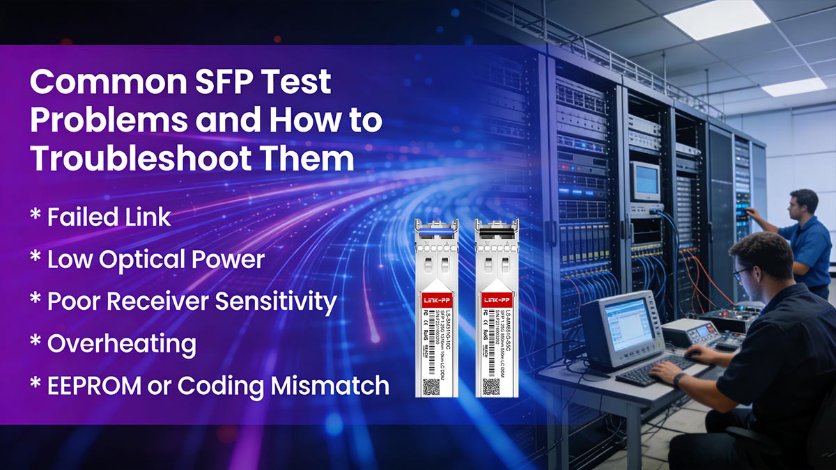
1. Failed Link
Symptoms:
Module does not establish a link
Port LED remains off or amber
Possible Causes:
Incorrect vendor coding or unsupported module
Dirty or damaged connectors/fiber
Optical power outside acceptable range
Troubleshooting Steps:
Check EEPROM coding and DDM/DOM information
Clean and inspect fiber connectors
Verify Tx/Rx power levels with an optical power meter
Test module in a known compatible switch
2. Low Optical Power
Symptoms:
Tx power below specification
Reduced link margin or intermittent errors
Possible Causes:
Laser degradation or misalignment
Fiber bend losses or connector contamination
Manufacturing defects
Troubleshooting Steps:
Measure Tx with an optical power meter
Inspect fiber path and connectors
Replace with a known good module to isolate the fault
3. Poor Receiver Sensitivity
Symptoms:
High BER despite proper Tx power
Signal loss over shorter distances than expected
Possible Causes:
Rx photodiode degradation
Excessive link loss or connector insertion loss
Incorrect receiver threshold settings
Troubleshooting Steps:
Use a VOA to test sensitivity under controlled conditions
Inspect connectors and fiber attenuation
Compare performance with a reference module
4. Overheating
Symptoms:
Elevated module temperature in DDM/DOM readings
Port shutdown or reduced performance
Possible Causes:
Insufficient airflow or poor heat dissipation
High-power laser operating beyond design spec
Thermal stress during testing
Troubleshooting Steps:
Check ambient temperature and airflow in test setup
Verify module temperature readings via DDM
Ensure module is within rated operating conditions
5. EEPROM or Coding Mismatch
Symptoms:
Switch reports “unsupported transceiver”
Module fails plug-and-play detection
Possible Causes:
Incorrect vendor ID, part number, or compliance coding
Corrupted EEPROM memory
Firmware mismatch between module and switch
Troubleshooting Steps:
Use an I²C/EEPROM analyzer to inspect data
Compare against vendor specifications
Re-flash or replace module if coding is incorrect
Most SFP failures are preventable with systematic testing and validation.
By carefully combining optical, electrical, environmental, and EEPROM checks, engineers can identify root causes quickly and avoid deployment issues. Maintaining a step-by-step troubleshooting workflow saves time, prevents costly downtime, and ensures network reliability.
🚩 FAQ: How to Test SFP Transceiver

Q1. What instrument is used to test an SFP?
Answer:
A complete SFP test setup uses multiple instruments:
Optical Power Meter (OPM) → Tx/Rx power measurement
Optical Spectrum Analyzer (OSA) → Wavelength and spectral analysis
Variable Optical Attenuator (VOA) → Sensitivity testing
Bit Error Rate Tester (BERT) → Data integrity
High-speed Oscilloscope / DCA → Eye diagram, jitter, rise/fall time
I²C/EEPROM Analyzer → DDM/DOM and memory checks
Host test board or real switches → Plug-and-play and interoperability
Each instrument targets a specific aspect of module performance, forming a full validation ecosystem.
Q2. How do you check if an SFP is bad?
Answer:
Check for these common failure indicators:
No link or port LED remains off
Tx power outside specification (too low or too high)
Rx sensitivity failing BER tests
Eye diagram violations or high jitter
DDM/DOM readings outside normal temperature, voltage, or optical range
EEPROM coding mismatch causing switch detection errors
Troubleshooting tip:
Compare module readings against a known good reference module
Inspect connectors, fiber, and host interface to rule out external causes
Q3. Can I test an SFP without specialized equipment?
Answer:
Basic link tests can be done with switch ports and LEDs, but this only shows if the module powers on and establishes a link.
Accurate performance validation requires professional instruments such as OPM, BERT, and DCA.
Visual inspection and link status alone cannot detect signal integrity or optical degradation.
Q4. What is the quickest way to verify SFP functionality?
Answer:
Insert the module into a compatible switch or host board
Check link establishment and DDM/DOM readings
Measure Tx/Rx optical power if possible
This method provides a rapid sanity check, but full testing is recommended for production or deployment-grade validation.
Q5. How often should SFP modules be tested?
Answer:
New modules: Always perform full optical, electrical, and compatibility testing before deployment
Installed modules: Periodically check DDM/DOM readings and link performance
After environmental stress or firmware updates: Revalidate to ensure continued reliability
Routine monitoring prevents unexpected failures in critical network infrastructure.
🚩 Best Practices for a Reliable SFP Testing Workflow
Creating a consistent, professional SFP testing workflow ensures that modules meet optical, electrical, diagnostic, and environmental standards while reducing the risk of deployment failures. Below is a step-by-step guide, including a pass/fail checklist and margin-testing recommendations for lab use.

1. Step-by-Step Lab Workflow
Visual Inspection & Initial Sanity Check
Inspect SFP module for physical damage or contamination
Confirm EEPROM coding, vendor ID, and part number
Optical Testing
Measure Tx power, Rx sensitivity, wavelength, and extinction ratio
Use an Optical Power Meter (OPM), OSA, and VOA
Capture eye diagrams and check optical loss margin
Electrical and Signal Integrity Testing
Perform BER testing using a BERT
Measure jitter, rise/fall times, and eye mask compliance
Validate high-speed signal quality at full rated speed
DDM/DOM and EEPROM Validation
Check temperature, voltage, and optical power readings
Validate EEPROM content and I²C communication
Compatibility Testing
Test module in real switches and routers across vendors
Verify plug-and-play functionality and firmware behavior
Conduct multi-vendor interoperability checks
Environmental and Reliability Stress Testing
Perform temperature cycling, humidity, vibration, burn-in, and thermal stress tests
Monitor optical and electrical performance during stress
Final Pass/Fail Evaluation
Compare test results against module specifications
Flag modules failing any critical criteria for rework or rejection
2. Pass/Fail Checklist
Test Category | Key Criteria | Pass/Fail Indicators |
|---|---|---|
Optical | Tx/Rx power, wavelength, extinction ratio | Within specification ± tolerance |
Electrical | BER, jitter, rise/fall time, eye mask | BER ≤ 10⁻¹², eye diagram within mask |
Diagnostics | DDM/DOM readings, EEPROM data | Values match reference; vendor ID correct |
Compatibility | Switch recognition, plug-and-play | Module detected, no errors |
Environmental | Temperature, humidity, vibration, burn-in | No degradation or failure |
Overall | Margin testing | All performance metrics exceed minimum standards |
3. Margin-Testing Recommendations
Test Tx power at reduced optical attenuation to verify headroom
Validate Rx sensitivity at maximum link loss to ensure reliability
Run BER and eye diagram checks under temperature extremes
Document operating margins to prevent field failures
Margin testing ensures modules are not only compliant but robust under real-world conditions.
4. Pro Tip: Sourcing Reliable Modules
To maintain high quality and consistency, source SFP transceivers from trusted vendors. For professional-grade modules that have been thoroughly tested for optical, electrical, and environmental compliance, visit LINK-PP Official Store. Their modules are widely used in enterprise and telecom deployments and come with verified performance documentation.
A structured SFP testing workflow, combined with systematic pass/fail checks and margin testing, ensures that modules are deployment-ready, compatible, and reliable.
Implementing these best practices reduces downtime, improves network reliability, and safeguards investments in high-speed optical infrastructure.


